

Page 1

Agilent 140/240/280
Series AA
Service Manual
Agilent Confidential
Agilent Technologies
Page 2

Notices
WARNING
CAUTION
NOTE
No part of this manual may be reproduced in
any form or by any means (including electronic storage and retrieval or translation
into a foreign language) without prior agreement and written consent from Agilent Technologies, Inc. as governed by United States
and international copyright laws.
Manual Part Number
G8434-90050
Edition
Rev. B, July 2017
Agilent Technologies
679 Springvale Road
MULGRAVE Victoria 3170, Australia
Printed in Australia
© Agilent Technologies, Inc. 2017
Warranty
The material contained in this document is provided “as is,” and is subject to being changed, without notice,
in future editions. Further, to the maximum extent permitted by applicable
law, Agilent disclaims all warranties,
either express or implied, with regard
to this manual and any information
contained herein, including but not
limited to the implied warranties of
merchantability and fitness for a particular purpose. Agilent shall not be
liable for errors or for incidental or
consequential damages in connection
with the furnishing, use, or performance of this document or of any information contained herein. Should
Agilent and the user have a separate
written agreement with warranty
terms covering the material in this
document that conflict with these
terms, the warranty terms in the separate agreement shall control.
Technology Licenses
The hardware and/or software described in
this document are furnished under a license
and may be used or copied only in accordance with the terms of such license.
Restricted Rights Legend
If software is for use in the performance of a
U.S. Government prime contract or subcontract, Software is delivered and licensed as
“Commercial computer software” as defined
in DFAR 252.227-7014 (June 1995), or as a
“commercial item” as defined in FAR
2.101(a) or as “Restricted computer software” as defined in FAR 52.227-19 (June
1987) or any equivalent agency regulation or
contract clause. Use, duplication or disclosure of Software is subject to Agilent Technologies’ standard commercial license
terms, and non-DOD Departments and Agencies of the U.S. Government will receive no
greater than Restricted Rights as defined in
FAR 52.227-19(c)(1-2) (June 1987). U.S. Government users will receive no greater than
Limited Rights as defined in FAR 52.227-14
(June 1987) or DFAR 252.227-7015 (b)(2)
(November 1995), as applicable in any technical data.
Safety Notices
A WARNING notice denotes a hazard. It calls attention to an operating procedure, practice, or the like
that, if not correctly performed or
adhered to, could result in personal
injury or death. Do not proceed
beyond a WARNING notice until
the indicated conditions are fully
understood and met.
A CAUTION notice denotes a hazard. It calls attention to an operating
procedure, practice, or the like that,
if not correctly performed or adhered
to, could result in damage to the
product or loss of important data. Do
not proceed beyond a CAUTION
notice until the indicated conditions
are fully understood and met.
A NOTE contains helpful information on usage - it does not denote a
hazard.
Confidentiality Notice:
Export License Restrictions apply to
the information in this Service Manual
and require that it only be made available to and be used by qualified Agilent
AA System Field Service Engineers.
The information contained in the Agilent 140/240/280 AA Series Service
Manual is for use only by Agilent
trained Field Service Engineers.
Do NOT disclose this information to any
other parties.
Agilent Confidential
Page 3

Foreword
NOTE
About this Manual
This manual contains information relating to the structure of the 140/240/280 Series
AA system, as well as information relating to maintenance, troubleshooting, peripheral
equipment, and service support parts. Step- by- step explanations are also provided to
enable efficient installation.
In Feb 2012, Agilent rationalized the AA product from 25 models with over 400
possible configurations to 14 models which included the most popular configurations
including as standard; auto lamp selection, double beam for all flame instruments, and
GTA camera on all GFAA models. Current available models are:
G8430A Agilent 55B AA Spectrometer
G8430AA Agilent 55B AA Spectrometer Bundle
G8431AA Agilent 240 AA Spectrometer Bundle
G8432AA Agilent 240FS AA Spectrometer
G8433AA Agilent 240FS AA Spectrometer with GTA Camera
G8434AA Agilent 280FS AA Spectrometer
G8435AA 240Z AA Spectrometer, no UltrAA Control
G8436AA Agilent 240Z AA Spectrometer
G8437AA Agilent 280Z AA Spectrometer
G8447AA 240FS/GTA120/PSD120/UltrAA System
G8448AA 240FS/SPS3/SIPS20 AA System
G8449AA AA Duo 240FS/240Z/UltrAA System
G8450AA AA Duo 55B/240Z/UltrAA System
G8442AA AA Duo 280FS/280Z/UltrAA System
Note that the contents included in this manual are subject to change without notice due to modifications
made to the product. Check the Support Portal or SubscribeNet regularly.
Using this Manual
The Agilent 140/240/280 Series AA Service Manual provides information which allows
Agilent Field Service Engineers (FSE) to install, maintain, and service the Agilent AA
system. This manual contains the following chapters:
Chapter 1, “General Information”
This chapter describes precautions for handling the Agilent AA system, specifications,
names and functions of key components, and explanations on the structure of each
system.
You should be aware of the general safety practices outlined in the Precaution section.
Chapter 2, “Removal/Installation, Replacement and Adjustment”
This chapter describes the methods for removal/installation, disassembly/assembly,
replacement and adjustment of the components of the AA system.
Agilent Confidential
Page 4

Chapter 3, “Troubleshooting”
NOTE
This chapter describes the instrument power-on self- tests and available diagnostics for
troubleshooting. Technical information on the electronics used in the AA system is
also provided as an aid to troubleshooting.
This chapter also contains explanations for error codes and error messages, as well as
causes and remedies for handling them.
Chapter 4, “Peripheral Equipment”
This chapter contains overviews of the optional equipment used with the 140/240/280
Series AA system components.
Chapter 5, “Service Parts”
This chapter provides assistance in searching for parts to be ordered based on
diagrams, and in specifying the part numbers.
Chapter 6, “Installation and Preventative Maintenance Guide”
This chapter describes the procedures for installing and setting up the Agilent AA
system.
Appendix A, “Technical Theory”
This appendix describes the technical theory behind the AA system.
Most information contained in this publication is relevant to the Agilent 140/240/280
AA instruments. Where information applies only to one instrument model, it shall be
clearly identified.
Agilent Confidential
Page 5

Contents
Foreword 3
About this Manual 3
Using this Manual 3
1 General Information
Precautions 16
General 16
Verifying Safe State 16
Electrical Hazards 17
High Voltage Devices 17
Heat, Vapors, and Fumes 18
Compressed Gas Hazards 18
Ultraviolet Radiation 19
Hazardous Materials 20
Other Precautions 20
Warning Symbols 21
Color Coding 22
CE Compliance 22
Electromagnetic Compatibility 23
EN55011/CISPR11 23
ICES/NMB-001 23
Flame Operation 24
Flammable Solvents 24
Compressed Gases and Cylinders for Flame Operation 25
Acetylene 25
Nitrous Oxide 26
Burners 26
Nebulizer 27
Liquid Trap 27
Heat Hazards 27
Perchloric Acid 28
Flashbacks 28
Furnace and Zeeman Operation 30
Gases 30
Heat Hazards 30
Vapors and Fumes 30
UV Radiation 31
Magnetic Field (Zeeman only) 31
Specifications 32
Weights and Dimensions 32
Optics 32
Primary Light Sources (Not supplied) 32
140/240/280 Series AA Service Manual Agilent Confidential 5
Page 6

Contents
Beam Arrangement 32
Background Correction (where fitted) 32
Monochromator 33
Gas Supplies (for flame instruments only) 33
Sample Introduction (flame instruments only) 34
Electrical Specifications 35
Electrical Supply 35
Agilent SpectrAA Windows software 37
Methods and Sequence 37
Performance 39
Environmental Conditions 39
Flame Performance 40
Furnace Performance 40
PC Requirements 40
Outline of Agilent AA System 41
Agilent AA Features 41
Instrument Overview 43
Flame Instruments Front View 43
Flame Instruments Rear View 44
Zeeman Instruments Front View 45
Zeeman Instrument Rear View 46
Furnace Instruments Front View (D
Furnace Instruments Rear View (D
- non Zeeman) 47
2
- non Zeeman) 48
2
System Structure and Key Components 49
Sample Introduction 50
Nebulizer 50
Nebulizer Block and Impact Bead 51
Liquid Trap 52
Spray Chamber 53
Burner 53
Burner Adjuster Assembly 56
Optics 58
Monochromator 59
Peaking on Spectral Lines 60
Slits 60
Background Correction 61
Lamp Selection 61
Lamp Recognition 62
Optics Chassis 63
UltrAA lamp Control Module 65
Gas Control 67
Programmable Gas Control Unit (PGCU) 67
Automatic Gas Control Unit (AGCU) 69
Ignition Interlocks 71
6 Agilent Confidential 140/240/280 Series AA Service Manual
Page 7

Oxidant Reservoir 72
Specifications 72
Gas Control Unit Flow Diagram 74
Accessories 76
2 Removal/Installation, Replacement and Adjustment
Tools and Supplies 79
Main Frame Covers 81
Replacing the Chimney 81
Removal 81
Installation 81
Replacing the Flame Shield/Viewing Window Assembly 82
Removal 82
Installation 82
Replacing the Flame Sample Compartment Front Panel (140/240/280) 82
Removal 82
Installation 82
Replacing the Flame Sample/Burner Compartment Heat Shield 82
Removal 82
Installation 83
Replacing the Left Front Molding/Panel 83
Removal 83
Installation 83
Replacing the Left Side Cover 84
Removal 84
Installation 84
Replacing the HCL Compartment Cover/Door 85
Removal 85
Installation 85
Replacing the Right Side Cover 85
Removal 85
Installation 86
Contents
Sample Introduction 88
Replacing the Burner 88
Removal 88
Installation 89
Replacing the Nebulizer Block/Spray Chamber Assembly 90
Removal 90
Installation 91
Replacing the Spray Chamber 91
Removal 91
Installation 92
Replacing the Pressure Relief Bung 92
Removal 92
140/240/280 Series AA Service Manual Agilent Confidential 7
Page 8

Contents
Installation 92
Replacing the Mixing Paddles 92
Removal 93
Installation 93
Replacing the Liquid Trap 93
Removal 93
Installation 94
Replacing the Nebulizer Block 94
Disassembling the Nebulizer 94
Cleaning a Blocked Nebulizer 95
Reassembling the Nebulizer 96
Replacing the Impact Bead 97
Removal 97
Replacing the Burner Adjuster Assembly 99
Removal 99
Installation 100
Replacing the Carriage from AGCU/PGCU Burner Adjuster 101
Removal 101
Installation 102
Replacing the Carriage from Automatic Burner Adjuster 103
Removal 103
Installation 106
Replacing the Ignition Interlocks 108
Removal 108
Installation 108
Optics 109
Replacing the Monochromator 110
Replacing the Slit/Motor Assembly 112
Replacing the Grating Assembly 114
Agilent AA140/240 114
Agilent AA280 114
Replacing the Micrometer Assembly 115
Agilent AA140/240 115
Agilent AA280 116
Replacing the Collimator Assembly 118
Replacing the Chopper Mirror Assembly 119
Replacing the UltrAA Lamp Module 120
Wavelength Calibration 122
Correcting Wavelength Using the Firmware 122
Zero Order Peaking 122
Slit Calibration 123
Wavelength Calibration 123
Optical Alignment 125
Preparation 126
8 Agilent Confidential 140/240/280 Series AA Service Manual
Page 9

Installing the Back-Lighting Tool 126
Sample Beam Alignment 127
For Zeeman Instruments 128
Reference Beam Alignment 128
M5D2 Alignment 130
Auto Lamp Select Mirror Alignment 132
Beam Balance 139
Dynamic Beam Balance Alignment 139
An Alternative to Using the Oscilloscope 139
Dynamic Beam Balance - SVD method 140
Beam Coincidence Check 141
Cleaning Mirrors 142
Gas Control Unit 143
Primary Service Position 143
Secondary Service Position 144
Replacing the Gas Control Unit 145
Removal 145
Installation 145
Gas Calibration 147
Kit Contents 147
Installing the Calibration Manifold 147
Performing Gas Calibration Using Air 148
AGCU (Automatic Gas Control Unit) Calibration 149
PGCU (Programmable Gas Control Unit) Calibration 152
Flow Measurements 157
Measuring Gas Flows 157
Installing Flow Gauge 157
Oxidant Flow 159
Acetylene Flow 160
Leak Checking 162
Contents
Electronics 163
Mains Input and Distribution 163
Replacing the Power Cable Inlet Connector (Corcom Module) 163
Removal 163
Installation 164
Replacing the PC Power Module 164
Removal 164
Installation 165
Replacing the Mains Transformer 166
Removal 166
Installation 167
Replacing the Monochromator Interface PCA 168
Removal 168
Installation 168
140/240/280 Series AA Service Manual Agilent Confidential 9
Page 10

Contents
Replacing the Main Control PCA 169
Removal 170
Installation 170
Replacing the Photomultiplier Interface PCA 172
Removal 173
Installation 173
Replacing the RBA Opto 174
Removal 174
Installation 174
Replacing the Triac Control PCA (Zeeman Instruments) 175
Removal 175
Installation 176
Replacing the SIPS Control and Power Module 177
Removal 177
Installation 177
Replacing the Flame Detector 178
Removal 178
Installation 178
3 Troubleshooting
Diagnostics 180
Power-on Self-Test 180
Main Control PCA, G8434-65750 180
Firmware Start Up Sequence 181
Service Diagnostic Program (SVD) 187
Executing Service Diagnostics 188
Menus 188
Startup Page 190
Instrument Configuration Tab 190
Optical Tests 195
Mechanical Tests Tab 202
Lamps 203
Miscellaneous 205
Zeeman Magnet Calibration 208
UltrAA Lamp Module Diagnostics 219
Diagnostic LEDs 219
Te s t P oi nt s 220
Troubleshooting 222
Minimum Information 222
Troubleshooting Chart 222
Error Messages 230
Structure 230
Format 230
Examples 231
10 Agilent Confidential 140/240/280 Series AA Service Manual
Page 11

Error Coding 231
Error Message Ranges 231
Error Message Help ID. 232
Help ID Description 256
Electronics 278
Overview 278
Mains Input and Distribution 279
PC Power Module 279
Setting the Supply Voltage 280
Zeeman Instruments 280
PC Power Module - Zeeman Instruments 281
Main Control PCA (G8434-65750) 282
History of the AA Control PCA 282
What happens if an AA control PCA configuration is wrong? 283
Configuring AA Control PCAs 284
Additional Information 287
Photomultiplier Interface PCA (G8434-65030) 288
Test Points and Links 288
Instrument Photometric Gain 289
Low Voltage Supplies 290
EHT Supply 290
Signal Processing 290
Flame Emission Compensation (FEC) 291
Voltage-to-Frequency Converter 291
Indicator LEDs, Switches, and Test Points 291
Low Voltage Supplies 293
Motor Drives 293
Digital to Analog Converters 294
Timing Generator 294
Diagnostics, Accessory Control and EEPROM 295
Board Revision Level 296
Gas Control 296
Igniter 297
Flow Control (PGCU) 297
Flame Sensor 297
Hollow Cathode Lamp Supplies 298
+30, +310, +550 Volt Supplies 299
D
Lamp Supply 299
2
Lamp Recognition 300
Upgrading Firmware (FLASH) 301
Updating the Instrument Operating Block 301
Sample Oscilloscope Traces and Timing Diagrams 302
PMT Interface PCA 302
Main Control PCA 303
Contents
140/240/280 Series AA Service Manual Agilent Confidential 11
Page 12

Contents
Timing Diagrams 306
Mono Interface PCA 308
4 HCL PCA (210177690) - Agilent-AA280 309
UltrAA Lamp Module (210142790) - Zeeman 310
4 Peripheral Equipment
Dynavac Air Compressor 314
Specifications 315
Installation 316
At Start-up 316
Air Pressure Calibration 317
Maintenance 318
Cleaning the Compressor Air Intake Filter 318
Cleaning the Air Service Unit Filter 319
Spare Parts 320
5 Service Parts
Mainframe Fitting Parts 322
Optics 324
Optical bench – 240/240FS/280FS 324
Optical bench – 140/240Z/280Z 325
Monochromator – AA280FS/Z 326
Monochromator – AA140/240/240FS 327
Monochromator – AA240Z 328
Auto Lamp Select – AA280 329
Auto Lamp Select – AA140/240 330
Manual Lamp Select – AA140/240 331
Photomultiplier Tube – AA140/240/280 331
Optics cover – AA140/240/280 332
Others 333
Electronics 335
PCA/Board 335
Wiring Looms 337
Gas Control 338
Gas Control Unit 338
Igniter 340
Burner Adjusters 341
Sample Introduction 343
Spray Chamber Mk 7, complete 343
Spray Chamber / Nebulizer Supplies 345
Others 346
12 Agilent Confidential 140/240/280 Series AA Service Manual
Page 13

Panel Hardware 346
Special Tools 347
Upgrade Kits 348
Miscellaneous 348
Parts Index 349
6 Installation and Preventative Maintenance Guide
Before You Start 352
Installing and Maintaining AA 140/240/280 Instruments 353
Installation and Preventative Maintenance References 353
AA Series Spectrometers Installation Checklist 354
AA Series Spectrometers Installation Scope of Work 363
AA Series Spectrometers Familiarization Checklist 386
AA Series Spectrometers Familiarization Scope Of Work 390
AA Accessories Installation Checklist 416
AA Accessories Installation Scope of Work 435
AA Series Accessories Familiarization Checklist 485
AA Series Accessories Familiarization Scope Of Work 496
AA Series Spectrometers PM Checklist 569
AA Series PM Scope Of Work 579
Contents
Water Hose Connection 609
Water Hose Fitting 611
A Technical Theory
Introduction 614
Basic Principles of Atomic Absorption 615
Nature of Atomic and Ionic Spectra 617
Ionization 619
Atomic Emission 620
The Absorbance - Concentration Relationship 621
Atomization 622
Flame Atomization 622
Elements by Air-Acetylene Flame 624
Elements by Nitrous Oxide - Acetylene Flame 624
Elements By Both Flame Types 625
Graphite Furnace Atomization 626
Platform Atomization 627
Chemical Modifiers 628
Use of Alternate Gases 629
Injection Modes 629
140/240/280 Series AA Service Manual Agilent Confidential 13
Page 14

Contents
Vapor Generation 630
Other Vapor Generation Designs 632
Cell Heating 632
Background Correction 632
Deuterium Technique 633
Smith Heiftje Technique 635
Zeeman Technique 636
Calibration Roll-over 639
Sensitivity Loss for Some Elements 640
Comparison of Background Correction Techniques 640
Optics 642
Lenses 642
Lamps 642
Mirrors 644
Slit Width 645
Monochromator 646
Gratings 649
Detectors 650
Single vs Double Beam Configurations 652
Single Beam Optics 652
Double Beam Optics 653
Glossary of Technical Terms in AA 655
Bibliography and Further Reading 662
References 662
14 Agilent Confidential 140/240/280 Series AA Service Manual
Page 15

Agilent 140/240/280 Series AA
Service Manual
1
General Information
This chapter provides an overview of the Agilent AA System and
contains important information on:
Precautions 16
General 16
Verifying Safe State 16
High Voltage Devices 17
Heat, Vapors, and Fumes 18
Compressed Gas Hazards 18
Ultraviolet Radiation 19
Hazardous Materials 20
Other Precautions 20
Warning Symbols 21
Color Coding 22
CE Compliance 22
Electromagnetic Compatibility 23
Furnace and Zeeman Operation 30
Specifications 32
Weights and Dimensions 32
Optics 32
Gas Supplies (for flame instruments only) 33
Sample Introduction (flame instruments only) 34
Electrical Specifications 35
Agilent SpectrAA Windows software 37
Performance 39
PC Requirements 40
Outline of Agilent AA System 41
Agilent AA Features 41
Instrument Overview 43
System Structure and Key Components 49
Sample Introduction 50
Optics 58
Gas Control 67
Accessories 76
Agilent Confidential 15
Agilent Technologies
Page 16

General Information
WARNING
CAUTION
NOTE
Precautions
General
.
An Atomic Absorption Spectrometer uses compressed gases and high voltages and
generates radiant energy and hazardous wastes including corrosive fluids and
flammable liquids. Careless, improper or unskilled use of this spectrometer can cause
death or serious injury to personnel, or severe damage to equipment and property.
All users of an Atomic Absorption (AA) instrument must be familiar with the correct
operating procedures.
Before servicing the various components of the Agilent AA instrument, observe the
following safety precautions.
A WARNING notice denotes a hazard. It calls attention to an operating procedure, practice, or the
like that, if not correctly performed or adhered to, could result in personal injury or death. Do not
proceed beyond a WARNING notice until the indicated conditions are fully understood and met.
A CAUTION notice denotes a hazard. It calls attention to an operating procedure, practice, or the like
that, if not correctly performed or adhered to, could result in damage to the product or loss of
important data. Do not proceed beyond a CAUTION notice until the indicated conditions are fully
understood and met.
.
A NOTE contains helpful information on usage - it does not denote a hazard.
Verifying Safe State
The following general safety precautions must be observed during all phases of
operation, maintenance, and service of this instrument.
To ensure continued safe use of the instrument after maintenance or service
procedures, verify the instrument is returned to a safe state for the user. This includes
running performance checks to verify the instruments safety systems are functioning
correctly. Check the general condition of the instrument during operation for wear or
signs of corrosion that are likely to inhibit function or safety.
Failure to comply with these precautions or with specific warnings elsewhere in this
manual violates safety standards of design, manufacture, and intended use of the
instrument. Agilent Technologies assumes no liability for the customer’s failure to
comply with these requirements.
16 Agilent Confidential 140/240/280 Series AA Service Manual
Page 17
General Information
WARNING
WARNING
WARNING
Electrical Hazards
Panels or covers that are secured by screws on the spectrometer and accessories may
be opened only by Agilent field service engineers. Consult the manuals or product
labels supplied with your computer, monitor, printer, water circulating system, and air
compressor to determine which parts are operator- accessible.
Replace blown fuses with ones of the size and rating shown in the text near to the
fuse holder.
Electrical Shock Hazard
To avoid electric shock this equipment must be disconnected from the mains supply before
servicing.
Electrical Shock Hazard
Do not touch electrical circuits, devices, and components of the spectrometer system and some
accessories. They operate at dangerous voltages. Contact with them can cause death, serious
injury, or painful electric shock.
Fire Hazard, Electrical Shock Hazard
• The spectrometer uses interlocks and covers that are designed to prevent accidental contact
with any potential hazards. If the instrument is used in any manner not specified by Agilent,
this protection provided by the equipment may be impaired. It is good practice to develop safe
working habits that do not depend upon the correct operation of the interlocks for safe
operation. It is essential that no interlock or cover is bypassed, damaged, or removed.
• Application of the wrong supply voltage, connection of the instrument to an incorrectly wired
supply outlet, or lack of proper electrical grounding can create a fire hazard or a potentially
serious shock hazard. This could seriously damage the instrument and any attached ancillary
equipment.
• Always use a 3-wire outlet with ground connection that is adequately rated for the load. The
installation must comply with local and national safety regulations. Use only an Agilent
supplied power cord.
Replace the power cord only with a cord equivalent to the one specified in the Site Preparation
Guide.
• Do not connect the instrument to the mains power supply until you have made sure that the
operating voltage is correctly set for the mains power supply in the specific outlet in the
laboratory in which the instrument is connected.
High Voltage Devices
140/240/280 Series AA Service Manual Agilent Confidential 17
The photomultiplier tube, deuterium (D2), hollow cathode lamps, and the UltrAA lamp
module operate at high voltages.
Appropriate warning labels are attached to the instrument in easily visible locations to
warn of the dangers in that area. This equipment has been designed to prevent
electric shock by using interlocks and/or covers on high voltage compartments to
restrict access to powered circuitry.
Page 18
General Information
WARNING
WARNING
WARNING
WARNING
WARNING
Electrical Shock Hazard
Do not touch the drive circuitry of the photomultiplier tube, deuterium (D
and UltrAA lamp module. Contact with the drive circuitry can cause death, serious injury, or
painful electric shock.
Electrical Shock Hazard
Never attempt to override or disable interlocks. Failure to observe this warning can result in death
or serious injury.
Always disconnect the mains power when you need direct access to the electronics.
Magnetic Hazard
The Zeeman magnet generates a variable magnetic field of 0.8 Tesla (at mains frequency) in the
workhead. Pacemakers and magnetic storage media must be kept at least 300 mm from the
magnet.
), hollow cathode lamps,
2
Heat, Vapors, and Fumes
Heat, ozone, vapors, and fumes generated by flame, furnace, and vapor generation
methods can be hazardous, and must be extracted from the instrument by an exhaust
system.
Health Hazard, Asphyxiation Hazard
Ensure that an exhaust system of the appropriate type is fitted (as specified in the Site Preparation
Guide and Checklist). The exhaust system must be vented to the outside air in accordance with
local regulations and never within the building. Regularly check the exhaust system by smoke test
to ensure that the exhaust system is functioning correctly. The exhaust fan must always be
switched on before lighting the flame.
Compressed Gas Hazards
Health Hazard, Asphyxiation Hazard
All compressed gases other than air can create a hazard if they leak into the atmosphere. Even
small leaks in gas supply systems can be dangerous. Any leak other than air can result in an
oxygen-deficient atmosphere which can cause death, serious injury, asphyxiation, or
anaesthesia. The area in which cylinders are stored and the area surrounding the instrument must
be adequately ventilated to prevent accumulations of gas.
18 Agilent Confidential 140/240/280 Series AA Service Manual
Page 19

General Information
WARNING
CAUTION
NOTE
WARNING
WARNING
Fire Hazard, Explosion Hazard
• Gas cylinders must be stored and handled strictly in accordance with local safety codes and
regulations. Cylinders must be used and stored only in a vertical position and secured to an
immovable structure or a properly constructed cylinder stand. Move cylinders only on a
properly constructed trolley. Never locate gas cylinders near a source of ignition or in a
position that is subject to direct heat.
• Keep cylinders cool. This rule applies to every cylinder of compressed gas. Cylinders have
pressure relief devices that release the contents of the cylinder if the temperature exceeds 52
°C (125 °F).
• Ensure that all cylinders are clearly labeled so that there can be no doubt about the contents. If
the cylinder label is not legible, do not use the cylinder - return it to your supplier. Always
ensure that you have the right cylinder before connecting the cylinder to the instrument.
• If air is supplied from a compressor, all moisture must be extracted from the air before it is
supplied to the gas control module. Moisture can affect the internal components of the gas
control system and create a potentially hazardous situation.
• Use only approved regulator and hose connectors - refer to the gas supplier’s instructions.
Keep gas cylinders cool and properly labeled. All cylinders are fitted with a pressure relief
device that will rupture and empty the cylinder if the internal pressure rises above the safe
limit. Ensure that you have the correct cylinder before connecting it to the instrument.
Use only ‘Instrument Grade’ gases with the spectrometer.
.
• Shut-off valves should be installed and easily accessible.
• Always ensure that the gas supplies are turned off at the cylinders or tanks after completing an
analytical procedure and at the end of the working day.
Ultraviolet Radiation
Flames, hollow cathode lamps, and deuterium lamps emit hazardous ultraviolet
radiation. This radiation can cause serious damage to eyes and skin.
Eye Hazard
Always wear safety glasses conforming to an approved standard, and certified or otherwise
warranted to protect the eyes from ultraviolet radiation. Never look directly at the light emitted by
a hollow cathode lamp.
Eye Hazard
The deuterium lamp used for background correction emits high levels of UV radiation. Never
operate the deuterium lamp unless it is correctly mounted in its holder and fitted in its operating
position. Always wear UV absorbing safety glasses when you do any visual alignments involving
an energized deuterium lamp.
140/240/280 Series AA Service Manual Agilent Confidential 19
Page 20

General Information
WARNING
WARNING
WARNING
WARNING
WARNING
Chemical Hazard
When using a flame, always operate the instrument with the flame shield closed, and the sample
compartment front panel and chimney in place.
Hazardous Materials
Before attempting any work on the sample compartment area, you must know exactly
what matrix of solutions has been running through the instrument and particularly
what types of solvents are involved.
Chemical Hazard
Always check that the sample introduction system has been thoroughly flushed out with distilled
water and that the contents of the drain or waste container are known and properly disposed of if
necessary before touching any part.
Health Hazard
Wash your hands and gloves thoroughly during sample compartment work. Avoid contact
between hands and eyes at all times during servicing of the instrument.
Other Precautions
Fire Hazard, Explosion Hazard, Toxic Hazard
• Use of the spectrometer and accessories may involve materials, solvents, and solutions that
are flammable, corrosive, toxic or otherwise hazardous. Careless, improper, or unskilled use of
such materials, solvents, and solutions can create explosion hazards, fire hazards, toxicity, and
other hazards which can result in death, serious personal injury, and damage to equipment and
property.
• Always ensure that laboratory safety practices governing the use, handling, and disposal of
such materials are strictly observed. These safety practices should include appropriate safety
clothing and safety glasses.
• Cooling air flow to the spectrometer and accessories must be unobstructed. Do not block the
ventilation grills on the spectrometer and accessories. Consult the manuals supplied with your
computer, monitor, printer, water circulating system, and air compressor for their specific
ventilation requirements.
20 Agilent Confidential 140/240/280 Series AA Service Manual
Personal Injury Hazard
• Take great care when working with glass or quartz parts to prevent breakage and cuts. This is
especially important when attaching plastic tubing to glass barbs.
• The spectrometer weighs approximately 69 kg (152 lb). To avoid injury to personnel or damage
to the instrument or property, always use a forklift or other suitable mechanical lifting device to
move the instrument. If a forklift is not available, the instrument will need to be lifted by two
people.
Page 21
General Information
CAUTION
Use only Agilent-supplied or approved spares with your instrument.
.
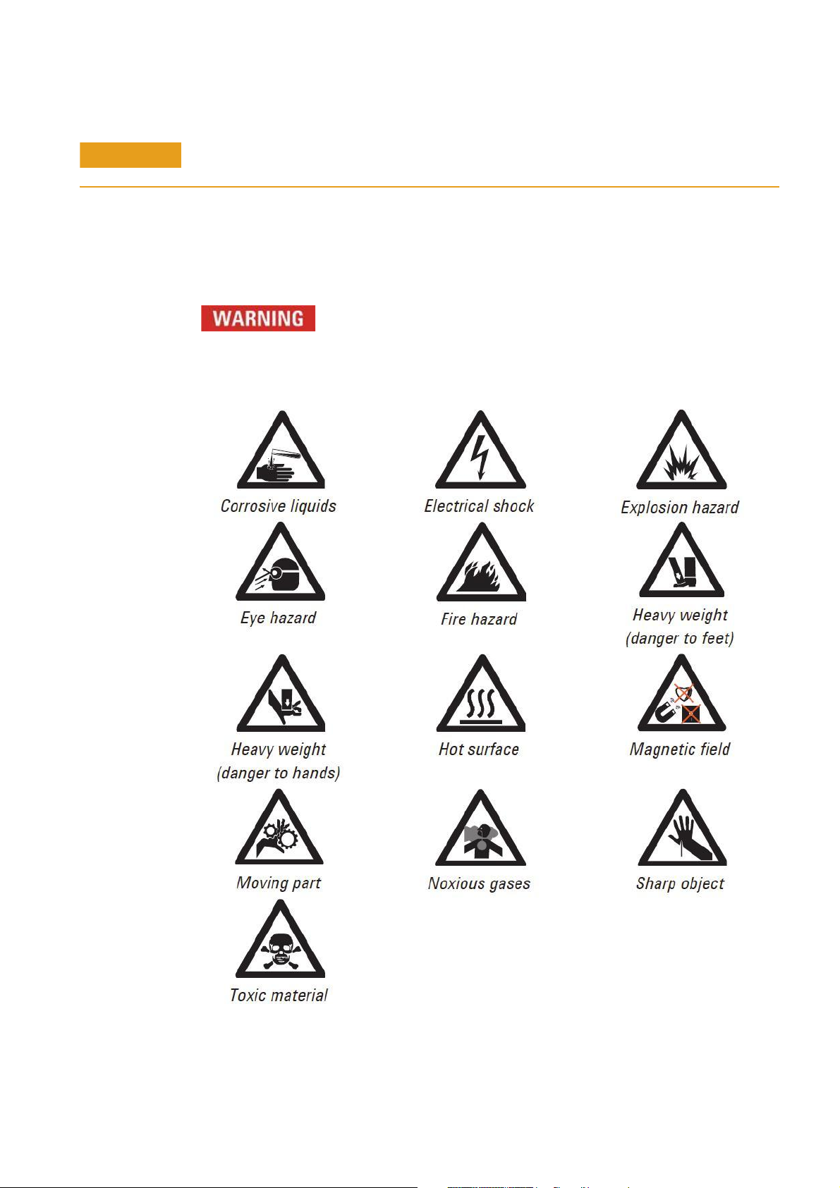
Warning Symbols
The following is a list of symbols that appear in conjunction with warnings in this
manual and on the spectrometer. The hazard they describe is also shown. The
beginning of the warning text is noted by a warning icon:
A triangular symbol indicates a warning. The meanings of the symbols that may
appear alongside warnings in the documentation or on the instrument itself are as
follows:
140/240/280 Series AA Service Manual Agilent Confidential 21
Page 22

General Information
The following symbol may be used on warning labels attached to the instrument. When
you see this symbol, refer to the relevant operation or service manual for the correct
procedure referred to by that warning label.
The following symbols appear on the instrument for your information.
Mains power on
Mains power off
Fuse
Single phase alternating current
Flame off
Flame on
Indicates lamp present
Disconnect all power plugs.
Caution, disconnect all supplies, risk of electric shock
Color Coding
The various indicator lights on the instrument and associated accessories are color
coded to represent the status of the instrument or accessory.
• A green light indicates the instrument is in normal/standby mode.
• An orange light indicates that a potential hazard is present.
• A blue light indicates that operator intervention is required.
• A red light warns of danger or an emergency.
CE Compliance
Your Agilent AA instrument has been designed to comply with the requirements of the
Electromagnetic Compatibility (EMC) Directive and the Low Voltage (electrical safety)
Directive (commonly referred to as the LVD) of the European Union. Agilent has
confirmed that each product complies with the relevant Directives by testing a
prototype against the prescribed EN (European Norm) standards.
Proof that a product complies with these directives is indicated by:
• The CE Marking appearing on the rear of the product, and
• The documentation package that accompanies the product containing a copy of the
Declaration of Conformity. The Declaration of Conformity is the legal declaration by
Agilent that the product complies with the directives listed above, and shows the
EN standards to which the product was tested to demonstrate compliance.
22 Agilent Confidential 140/240/280 Series AA Service Manual
Page 23

General Information
Electromagnetic Compatibility
EN55011/CISPR11
Group 1 ISM equipment: group 1 contains all ISM equipment in which there is
intentionally generated and/or used conductively coupled radio- frequency energy that
is necessary for the internal functioning of the equipment itself.
Class A equipment is equipment suitable for use in all establishments other than
domestic and those directly connected to a low voltage power supply network that
supplies buildings used for domestic purposes.
This device complies with the requirements of CISPR11, Group 1, Class A as radiation
professional equipment. Therefore, there may be potential difficulties in ensuring
electromagnetic compatibility in other environments, due to conducted as well as
radiated disturbances.
Operation is subject to the following two conditions:
1 This device may not cause harmful interference.
2 This device must accept any interference received, including interference that may
cause undesired operation.
If this equipment does cause harmful interference to radio or television reception,
which can be determined by turning the equipment off and on, the user is encouraged
to try one or more of the following measures:
1 Relocate the radio or antenna.
2 Move the device away from the radio or television.
3 Plug the device into a different electrical outlet, so that the device and the radio or
television are on separate electrical circuits.
4 Make sure that all peripheral devices are also certified.
5 Make sure that appropriate cables are used to connect the device to peripheral
equipment.
6 Consult your equipment dealer, Agilent Technologies, or an experienced technician
for assistance.
Changes or modifications not expressly approved by Agilent Technologies could void
the user’s authority to operate the equipment.
ICES/NMB-001
This ISM device complies with Canadian ICES-001.
Cet appareil ISM est conforme à la norme NMB- 001 du Canada.
140/240/280 Series AA Service Manual Agilent Confidential 23
Page 24

General Information
Flame Operation
Unskilled, improper, or careless use of flammable solvents in or near an atomic
absorption spectrometer can create explosion hazards and fire hazards. This can result
in death, severe personal injury, or burns.
The combination of a flame and flammable solvents can present a serious hazard. All
relevant safety practices governing the use of flammable solvents must be strictly
followed.
To reduce the possibility of fire or explosion:
• When selecting an organic solvent, choose a solvent that has the highest flash point
• Never use a solvent with a specific gravity lower than 0.75.
• Never leave uncovered containers of flammable solvent standing near the burner.
• Always use solvent-resistant tubing such as nitrile rubber for the drainage system
• Use small, wide- necked waste vessels and empty them frequently - do not
• When your analytical program is completed, or at the end of the working day,
• When your analytical program is completed, or at the end of the working day,
• Do not mix nitric or perchloric acid residues with organic solvent residues.
• Keep the burner slot, spray chamber, and liquid trap clean.
• Always use the internal igniter to light the flame as the flame will not operate
Flammable Solvents
consistent with your analytical requirements.
When aspirating such solvents, always use a covered container and feed the
capillary tubing through a 2- mm diameter hole in the cover. Always use the
smallest volume of solvent consistent with your analytical requirements.
and the vapor vent. Lead the drainage tube to a suitable wide- necked waste vessel
(as described in the next paragraph). The standard plastic laboratory tubing
supplied with your instrument is not suitable for draining organic solvents or
venting organic vapors. If organic or toxic solutions are used in the spray chamber,
vent tubing must be connected to the vapor vent on the liquid trap, run parallel to
the drain tubing, and led to an active exhaust system. Do not lead the vapor tubing
to the waste vessel. If you are not using toxic or hazardous liquids in the spray
chamber, leave the vapor vent uncovered.
accumulate large volumes of flammable solvent. Do not use glass waste vessels -
use vessels made of a material that will not shatter in the event of a flashback.
Metal vessels will corrode and it is difficult to determine the level of liquid in them.
Ensure that your waste vessel is below the instrument and located in an open,
well- ventilated position where you can see it. Never locate the vessel in a confined
space.
always empty and rinse the waste vessel.
always empty, clean, and refill the liquid trap.
unless all the safety interlocks are in enabled.
24 Agilent Confidential 140/240/280 Series AA Service Manual
Page 25

Figure 1 System setup diagram
General Information
Compressed Gases and Cylinders for Flame Operation
This spectrometer must only be used with air, nitrous oxide, and acetylene for flame
operation.
Never use oxygen or oxygen- enriched air as the oxidant because this results in an
explosion.
Never use any gas except acetylene as the fuel gas.
Acetylene
Unskilled, improper, or careless use of acetylene can create explosion hazards and fire
hazards that can result in death, severe personal injury, or burns.
Use acetylene at pressures lower than 105 kPa (15 psig). At pressures above this level,
acetylene can explode spontaneously. Your Agilent AA is designed to operate at fuel
supply pressures between 65 and 100 kPa (9.5.14.5 psig). Refer to the ‘Specifications’
section or the rear of the instrument for the exact range and recommended pressure.
Do not use any tubing or connector that reacts chemically with acetylene. Never pass
acetylene through copper tubing, or brass tubing or fittings containing more than 65%
copper, as this may cause an explosion. Never bring acetylene into direct contact with
copper, silver, liquid mercury, gaseous chlorine, or grease, this may cause an
explosion.
Use only acetylene that is packed in acetone. Some gas suppliers offer acetylene
packed in material other than acetone. While these alternatives may overcome some of
the disadvantages of acetone, they may also introduce the more serious problem of
corrosion in the gas control module and must not be used with Agilent atomic
absorption spectrometers.
If the pressure in the acetylene cylinder is allowed to fall below 700 kPa (100 psig), or
the consumption is greater than 1/7 of the cylinder contents per hour, acetone may be
carried over from the cylinder and into the spectrometer. Acetone in the spectrometer
can damage seals, O- rings, and hoses, degrade analytical performance and precipitate
flashbacks.
140/240/280 Series AA Service Manual Agilent Confidential 25
Page 26

General Information
Minimize the amount of acetone that is carried over with the acetylene by:
• Replacing cylinders when the pressure of the contents drops below 700 kPa
• Ensuring that the rate of acetylene drawn off from each cylinder is not excessive.
If there are high rates of consumption, connect two or more cylinders in parallel to a
manifold. This reduces the rate at which acetylene is drawn from each cylinder.
To reduce the possibility of fire or explosion:
• Test the supply ‘plumbing’ regularly for leaks with a brush and soapy water or a
• ‘Crack’ the cylinder before use by gently opening the valve to check for any drops
Use ‘Instrument Grade’ acetylene that is at least 99.5% pure.
Turn off fuel gas at the cylinder when you have completed your flame analysis.
Refer also to your local regulations governing the use of acetylene.
(100 psi)
proprietary leak- detecting solution (never use a naked flame when testing for leaks)
or spray of acetone. Any cylinder showing acetone should be returned to the
supplier for replacement.
Nitrous Oxide
The decompression of high- pressure N2O gas at the regulator can cause excessive
cooling and eventual freezing of the regulator. To prevent regulator malfunction and
possible flashback, the gas should be heated with an in- line or wrap- around heater.
Burners
Improper or careless use of burners can create explosion hazards and fire hazards
that can cause death, serious injury, and damage to equipment and property.
Whenever you handle burners, remember that the burner may be very hot. Always use
protective gloves to handle burners.
Burners are clearly identified by the fuel/oxidant combination for which they are
intended. Always fit the correct burner. Never attempt to use an air- acetylene burner
for nitrous oxide-acetylene, as this causes a flashback.
Use only acetylene as the fuel gas.
Use only air or nitrous oxide as the oxidant. Never attempt to use oxygen or
oxygen- enriched air, as this causes a flashback.
Burner interlocks are used to minimize the possibility of using the wrong burner.
Never interfere with or attempt to bypass any interlock fitted to this instrument.
To minimize the rate of burner blockage, the burner slot must be cleaned and polished
as described in the ‘Maintenance and Troubleshooting’ chapter of the User’s Guide.
Never allow burners to become blocked. Progressive burner blockage can increase the
static pressure in the liquid trap to the point at which the liquid seal is breached.
This can cause a flashback and create an explosion hazard or a fire hazard.
Never allow carbon to build up on the slot, as glowing particles can dislodge and fall
through the slot, causing a flashback.
Always turn off the flame before attempting to clean the burner slot. Never clean the
slot of a burner while a flame is running.
Never leave a flame unattended.
26 Agilent Confidential 140/240/280 Series AA Service Manual
Page 27

General Information
Never disassemble or modify a burner. Never use a damaged burner.
Nebulizer
Incorrect assembly and fitting of nebulizers to an atomic absorption spectrometer can
create explosion hazards and fire hazards that can cause serious injury and damage to
equipment and property.
Ensure that the nebulizer is correctly assembled and correctly fitted to the spray
chamber before lighting the flame. Nebulizers should be correctly adjusted before
lighting the flame.
Never remove a nebulizer from the spray chamber while the flame is on, and do not
use a mechanical device (for example, a wire) to clean the capillary of a nebulizer
while a flame is operating. Always extinguish the flame before removing the nebulizer
from the spray chamber.
Regularly test all connections for leaks. Fix all leaks before lighting the flame.
Liquid Trap
Improper use of the liquid trap can create explosion hazards, fire hazards, and toxic
vapor hazards that can result in death or serious injury.
The liquid trap interlock is used to minimize the possibility of operating the
instrument with an empty trap. Never interfere with this interlock. Never attempt to
bypass this interlock.
Always fill the liquid trap with the same solvent that is being used for your samples.
The trap is designed to provide a liquid seal under all normal conditions for solutions
with a specific gravity greater than 0.75. Never use a solution or solvent with a
specific gravity lower than 0.75, otherwise the liquid seal can be breached. This can
create a flashback and create an explosion hazard or a fire hazard.
A length of tubing must be connected to the drain outlet on the trap and led to a
suitable waste vessel. The free end of the tubing must remain above the liquid in the
waste vessel. Do not use glass waste vessels, use vessels made of a material that will
not shatter in the event of a flashback.
A length of tubing should be connected to the vapor vent (the upper nipple) on the
liquid trap when you are analyzing organic or toxic liquids. This tubing should be led
out from the sample compartment, parallel to the drain tubing, and must slope
downwards to enable any liquid overflow to drain out and prevent the tubing from
becoming blocked. Do not lead the vapor tubing to the waste vessel. If necessary, an
active exhaust system should be used to draw away toxic vapors. If you are not
analyzing solutions of a toxic nature, leave the vapor outlet uncovered.
Heat Hazards
An open flame, burners, and other hot surfaces can present heat hazards that can
result in severe burns.
When operating a flame system, always operate your spectrometer with the flame
shield closed, and the sample compartment front panel in place. Keep your hands out
of the sample compartment while a flame is burning.
When operating a flame system make sure that the chimney is in place with the
cutaway skirt (if present) to the back. Before you touch the instrument chimney, turn
off the flame and allow the chimney to cool.
140/240/280 Series AA Service Manual Agilent Confidential 27
Page 28

General Information
NOTE
When you change burners, remember that the burner may be very hot. Always use
protective gloves when removing a burner from the instrument.
Aspiration of perchloric acid perchlorates into a nitrous oxide- acetylene flame and can
create an explosion hazard that can result in death or serious injury, including
temporary or permanent impairment of hearing.
Do not use perchloric acid unless it is absolutely essential for sample preparation. If
perchloric acid must be used, you may be able to reduce the risk of explosion by
taking the following measures:
• Use an air-acetylene flame instead of a nitrous oxide- acetylene flame.
• Reduce the concentration of perchloric acid and metal in all analytical solutions to
• Aspirate all solutions for the shortest practicable period.
• Aspirate distilled water between samples. Minimize the aspiration of air.
• Use separate spray chamber/liquid trap and drain assemblies for perchloric acid
Perchloric Acid
the lowest practicable level. The concentration of perchloric acid should be reduced
in the digestion stage and further reduced by extending the fuming stage.
analyses and organic solvent analyses to prevent perchloric acid from mixing with
organic solvent residues.
When solvent extractions of perchloric solutions are performed, some of the acid may dissolve in the
organic solvent that is subsequently aspirated. Also, if the organic solution is aspirated while floating on
the surface of the acid, do not allow the capillary tube to drop below the organic layer and suck up
aqueous perchloric acid.
When using perchloric acid, wear approved ear protectors and approved safety glasses
and ensure that all instrument safety covers are in position.
Flashbacks
A flashback is an explosion of the gas mixture in the spray chamber, which can occur
for several reasons. For more details, refer to the SpectrAA software Help.
Agilent AA spectrometers have several safety features in place to prevent flashbacks,
and flashbacks are very rare in circumstances where instruments are properly
maintained.
In the rare event that a flashback does occur, the Agilent AA instrument safety
features are designed to safely relieve the pressure and minimize damage. In addition
to reading the list below, refer to the ‘Maintenance and Troubleshooting’ chapter of
the User’s Guide and the SpectrAA software Help for recommended maintenance
procedures to prevent flashbacks.
Analysis over many years has shown that in most cases, flashbacks are associated
with one or more of the following points. If you experience a flashback, check this list
to see if any of the points are relevant, and take steps to remedy the situation.
1 Keep the burner clean. Deposits must not be allowed to build up in or on the
burner slot because they can partially block it (thus causing the pressure to build
up in the spray chamber and breach the seal provided by the liquid trap), or
glowing particles can fall down through the slot into the spray chamber and ignite
the combustible gas mixture inside.
The use of a hard object to brush off glowing carbon particles during flame
28 Agilent Confidential 140/240/280 Series AA Service Manual
Page 29

General Information
operation is not recommended because of the increased risk of knocking one of the
particles down the slot. When using an organic solvent, a reduced uptake rate
should be used to restrict the amount of liquid fuel that is fed to the flame.
2 The width of the burner slot must not exceed the maximum design specification
[Mark VIA: 0.47 mm (0.0185 in) for N2O; Mark 7 0.46 mm (0.0181 in) for N2O; or
0.54 mm (0.021 in) for air]. Even a small increase in width can greatly increase the
possibility of a flashback occurring.
The burner slot must be regularly cleaned according to the instructions included in
the ‘Maintenance and Troubleshooting’ chapter of the User’s Guide.
3 Ensure that the spray chamber and liquid trap are kept clean. If dirty solutions are
being analyzed (for example, engine oils), ensure that the spray chamber, liquid
trap, float, and drain tube are regularly cleaned and flushed with a suitable solvent
so that sludge does not build up in the parts.
4 Ensure that the correct O- rings are used on the burner, nebulizer block, and
nebulizer, and that they remain undamaged.
Damage to O- rings in the spray chamber can result in gas leaks that can be ignited
by the flame and in turn set fire to the spray chamber.
Damage to O- rings in the nebulizer can result in oxidant leaks that can reduce the
total flow of gas through the burner slot and so increase the possibility of a
flashback occurring.
5 The liquid trap must be filled with the same solution as the matrix used for the
standards and samples.
6 The drain tube must be attached to the lower nipple of the liquid trap, and it must
slope downwards all the way to the drain vessel so that the waste liquid drains
smoothly.
The end of the drain tube must not be allowed to drop below the level of the liquid
in the vessel. (Also, the level of liquid must not be allowed to rise above the end of
the tube.)
When using organic or toxic liquids in the spray chamber, a vent tube must be
attached to the upper vent nipple of the liquid trap. It must slope downwards
(running parallel to the drain tube) to prevent it becoming blocked should any
liquid drain out, and be vented to an active exhaust system.
All the above points must be observed because a sudden surge of waste liquid can
affect the pressure in the spray chamber and result in a flashback.
7 Since N
O is stored in the cylinder under pressure as a liquid, when it expands
2
through the regulator it can cool the regulator sufficiently to form ice on the
outside and prevent it from operating correctly.
Prevent freezing by using a heater on the N
O regulator on the supply cylinder.
2
Contact the supplier of the regulator for a suitable heater.
8 As free acetylene is unstable at elevated pressure, it has to be stored in the
cylinder by dissolving it in acetone. If the gas is withdrawn too quickly, or the
cylinder pressure is allowed to drop below 700 kPa, acetone may be drawn off in
sufficient quantities to affect analytical performance, damage seals, O- rings, and
hoses, or even cause a flashback. Observe the recommendations concerning the use
of acetylene.
9 Where possible, do not perform digests with perchloric acid. As this acid is known
for forming unstable salts, operators using this acid should ensure that the
minimum amount is allowed to reach the spectrometer, and that the burner, spray
chamber, and liquid trap are thoroughly cleaned after each analysis to ensure that
unstable salts are not allowed to build up. Failure to do this can result in
unpredictable flashbacks.
140/240/280 Series AA Service Manual Agilent Confidential 29
Page 30

General Information
10 Aspirating solutions (especially alkaline/ammoniacal ones) that contain high
If a flashback or flame event occurs,
• Immediately press the red flame- off button to turn off gas f low to the instrument.
• Turn off the gas supply.
• Turn off power to the instrument.
• Inspect the sample introduction components including the burner, spray chamber,
• Check burner condition and O- rings for damage.
• Check O- rings for the spray chamber, especially the pressure relief bung for
• Check the nebulizer for damage.
• Check the windows on either side of the flame area for damage.
• Clean up any spills in the sample introduction area or on the instrument.
• Follow the Agilent Product Safety procedures for flashbacks. These procedures can
concentrations of Ag and Cu can lead to the formation of acetylides that can
spontaneously decompose and cause a flashback.
and nebulizer and clean or replace as necessary.
damage.
be found in two documents:
• Product Safety Event (PSE)
• AA Flashback Incident Questionaire
For further details refer to Service Note Number: AA- 275, AA Flashback Incident
Questionaire and Product Safety Event (PSE)
(The following SPARK website may also be useful:
https://spark.it.agilent.com/message/27517#27517)
Furnace and Zeeman Operation
Gases
The graphite tube atomizer (GTA120) gas supply system is designed for use with inert
gases and air. For more details and service information about the GTA120, refer to the
GTA120-120Z and PSD120 service manual.
Do not use pure hydrogen with the graphite tube atomizer since this could result in
leakage and potentially explosive accumulation of hydrogen. You can use a proprietary,
prepackaged mixture of 95% argon (or nitrogen) and 5% hydrogen. Do not attempt to
create your own mixture of hydrogen and an inert gas for use with the GTA system.
Heat Hazards
A hot furnace atomizer can present heat hazards that can result in severe burns.
Never put your hands in the sample compartment while you are operating your
furnace.
Allow the furnace atomizer to cool before removing it from the sample compartment.
Vapors and Fumes
Do not place your head over the graphite tube atomizer while it is operating. This
could cause inhalation of hazardous or toxic fumes, or your skin and eyes could be
injured by corrosive vapors or fumes.
30 Agilent Confidential 140/240/280 Series AA Service Manual
Page 31

General Information
The chimney or the optional exhaust accessory must be in place for furnace operation
to ensure that toxic vapors and heat are exhausted.
UV Radiation
When viewing the sample during the drying stage, use only a rear coated mirror (as
supplied) or the optional Tube- CAM. Do not look directly at the furnace during either
the ash or atomize stages.
Magnetic Field (Zeeman only)
The magnet produces a variable magnetic field of up to 0.8 Tesla peak at mains
frequency in the workhead during the read stage.
To avoid interference with heart pacemakers or magnetic storage media, keep them at
least 300 mm from the magnet.
140/240/280 Series AA Service Manual Agilent Confidential 31
Page 32

General Information
Specifications
Weights and Dimensions
System unit Width Depth Height Weight
240 AA spectrometer 790 mm (31 in) 580 mm (23 in) 590 mm (23 in) 56 kg (123 lb)
240Z AA spectrometer. Also
requires GTA 120Z
240 AA shipping dimensions 1215 mm (46 in) 820 mm (35 in) 870 mm (35 in) 97 kg (214 lb)
240Z AA shipping dimensions 1215 mm (46 in) 820 mm (35 in) 870 mm (35 in) 86 kg (190 lb)
280FS AA spectrometer 790 mm (31 in) 580 mm (23 in) 590 mm (29 in) 75 kg (165 lb)
280Z AA spectrometer. Also
requires GTA 120Z
280FS/Z AA shipping dimensions 1210 mm (48 in) 820 mm (32 in) 1020 mm (40 in) 106 kg (234 lb)
790 mm (31 in) 580 mm (23 in) 590 mm (23 in) 56 kg (123 lb)
790 mm (31 in) 580 mm (23 in) 740 mm (29 in) 61 kg (135 lb)
Optics
Primary Light Sources (Not supplied)
Hollow Cathode Lamps (HCL) Standard
UltrAA lamps Optional for AA140/240/240FS/240Z/ 280FS
Standard for AA280Z
* Refer to brochures for the full range of available lamps.
** All HCLs are available with recognition-coded bases.
Eight fixed-position lamps
Automatic lamp selection
Lamps are individually adjustable to the optical path
** On the AA280 Fast Sequential, 8 HCLs can be simultaneously powered up to 90 mA (45 mA per bank of 4 lamps) and
on the 280Z, 1 operating HCL and 1 on standby.
Beam Arrangement
Non-Zeeman Double/single beam
Zeeman Single beam
Reflective surfaces are designed for constant focus at all wavelengths and are hard–dielectric coated for high
performance and corrosion resistance.
Background Correction (where fitted)
Non- Zeeman
Continuum source Deuterium (D
Wavelength range 180 to 423 nm approx
lamp supply Switch-mode, current regulated, 40 mA (avg) approx
D
2
D2 duty cycle 20% at 50 Hz, 24% at 60 Hz
) lamp
2
32 Agilent Confidential 140/240/280 Series AA Service Manual
Page 33

General Information
WARNING
Zeeman
Magnetically separated and polarized sample beam pair generated in the workhead by the Zeeman effect with
rejection of one polarized component by a polarizer in the sample beam. The Zeeman effect background corrector
corrects to greater than 2.0 Abs background from 185 to 900 nm.
Monochromator
Instrument Agilent AA140/240 Agilent AA280
Type Czerny–Turner Czerny–Turner
Dispersing method Grating, 27 x 35 mm, 1200 lines/mm Grating, 30 x 35 mm, 1800 lines/mm
Focal length 252 mm 331.8 mm
Reciprocal linear dispersion 3 nm/mm at 250 nm 1.6 nm/mm at 250 nm
Blaze wavelength 250 nm 250 nm
Wavelength range 185 to 900 nm (and zero order) 185 to 900 nm (and zero order)
Wavelength accuracy ±0.37 nm ±0.37 nm
Wavelength repeatability ±0.04 nm ±0.035 nm
Wavelength drive Software controlled motor drive Software controlled motor drive
Slew rate 2000 nm/min 2025 nm/min
Scan direction Decreasing wavelength Decreasing wavelength
Wavelength readout Four digit display on PC screen Four digit display on PC screen
Slits, normal height 0.2, 0.5, 1.0 nm (flame atomizer) 0.1, 0.2, 0.5, 1.0 nm (flame atomizer)
Slits, reduced height 0.5 nm (furnace atomizer) 0.5 nm (furnace atomizer)
Slit drive Software controlled motor drive Software controlled motor drive
Slit repeatability To ±2% of nominal energy To ±2% of nominal energy
Gas Supplies (for flame instruments only)
The Agilent AA flame instrument is to be used only with air or nitrous oxide and acetylene for
flame operation.
Do not use oxygen or oxygen–enriched air as a combustion support gas. This will cause an
explosion. Do not use hydrogen as the fuel gas as it may leak into the instrument and cause an
explosion. Explosion hazards may also result from the use of other unspecified gas mixtures.
140/240/280 Series AA Service Manual Agilent Confidential 33
Compressed air supply Air supply must be clean, dry, and oil free
Air filter Recommended if a compressor is being used
Recommended pressure 350 kPa (50 psi)
Pressure range 245 to 455 kPa (35 to 65 psi)
Maximum flow rate 20 L/min
Page 34

General Information
CAUTION
Nitrous oxide supply Instrument grade (99.5% pure)
Recommended pressure 350 kPa (50 psi)
Pressure range 245 to 455 kPa (35 to 65 psi)
Maximum flow rate 16 L/min
Acetylene supply Instrument grade (99.0% pure). Must be packed in acetone
Recommended pressure 75 kPa (11 psi) at the instrument
Pressure range 65 to 100 kPa (9.5 to 14.5 psi) at the instrument
Maximum flow rate 10 L/min
Pressure in the acetylene storage cylinder must be maintained in excess of 700 kPa (100 psi) to
prevent acetone entering the gas lines.
Refer to “Gas Control” on page 67 for complete gas specifications.
Sample Introduction (flame instruments only)
Nebulizer
Platinum/iridium capillary
PEEK venturi
Adjustable to hi–vac and hi–solids positions
Burner
Mark 7 Air/Acetylene burner
Mark 7 Nitrous oxide/Acetylene burner
Flame ignition
Tongue of flame, spark ignition
Burner adjuster
Manual/Automatic vertical motion
Manual horizontal motion
Manual rotation
Spray chamber
Mark 7 polypropylene standard
Twin head mixing paddles
Externally finger-adjustable impact bead
Safety interlocks
Burner present
Burner type
Flame sensor
Flame shield
Pressure relief bung
Liquid trap level
Oxidant/safety tank pressure
Mains power
Gas control
34 Agilent Confidential 140/240/280 Series AA Service Manual
Page 35

General Information
NOTE
Programmable flame stoichiometry (gas mix)
On demand display of gas parameters
Interlocked ignition sequencing
Automatic flame changeover
Automatic dilution of combustible mixtures for safe flameout
Electrical Specifications
The installation of electrical power supplies must comply with the rules and/or
regulations imposed by the local authorities responsible for the use of electrical energy
in the work place.
All Agilent AA instruments are supplied with a 2 meter (6' 6") mains power cord
terminated as indicated in Table 1.
All power supplies should be single phase AC, 3 wire system (active, neutral and
ground, or two actives and ground) and should be terminated at an appropriate
connection receptacle that is within reach of the system power cable assembly. In
areas where 208/220/240 Volt supplies are not normally available in a single phase
configuration, supplies may be taken from two phases and ground using a three phase
system.
A separate connection receptacle should be provided for each unit in the system. Do
not use double adapters or extension cords.
A separate mains circuit individually protected by fuses or circuit breakers must be
used for the GTA accessory. It is preferable for the GTA and the instrument to share
the same phase.
If the system being installed is a Zeeman system, then two separate mains circuits individually protected
by fuses or circuit breakers must be used — one each for the instrument and the Zeeman GTA accessory.
It is preferable for the GTA and the instrument to share the same phase but separate power supply
circuits.
Avoid using power supplies from a source that may be subject to electrical interference from other
services (large electric motors, elevators, welders, air conditioning units, etc.).
Electrical Supply
Tab l e 1 Electrical specifications for Agilent AA systems
System unit Required supply voltage Rating
55B AA spectrometer 100, 120, 220 or 240 VAC, 50/60 Hz 170 VA
240 AA spectrometer 100, 120, 220 or 240 VAC, 50/60 Hz 170 VA
280 AA spectrometer 100, 120, 220 or 240 VAC, 50/60 Hz 230 VA
240 Z AA spectrometer 208-240 VAC, 50/60 Hz 1000 VA*
280 Z AA spectrometer 208-240 VAC, 50/60 Hz 1000 VA*
GTA Graphite Tube Atomizer (GTA 120) 208/220/240 VAC, 50/60 Hz 15 A*
SIPS 10/20 Sample Introduction Pump System 100-240 VAC 70 W
SPS 4 Autosampler 100-240 VAC, 50/60 Hz 24 VDC, 2.5 A
VGA 77 Vapor Generation Accessory 100, 120, 220 or 240 VAC, 50/60 Hz 20 VA
140/240/280 Series AA Service Manual Agilent Confidential 35
Page 36

General Information
Tab l e 1 Electrical specifications for Agilent AA systems
System unit Required supply voltage Rating
ETC 60 Electrothermal Temperature Controller 110-120, 220-240 VAC, 50/60 Hz 755 VA maximum
UltrAA Boosted Lamp Supply 100, 120, 220 or 240 VAC, 50/60 Hz 150 VA
* In normal operation, the Zeeman and GTA units will draw surge currents in excess
of the nominal rating. Power supplies to these units must be isolated from other
supplies to the system, and should include delayed action protection devices such as
circuit breakers or motor start fuses.
The VA and current figures above are the typical continuous VA and current drawn by
AA and GTA. During the atomize cycle, surge currents for very short spans of time
(between 1 and 5 second) may be drawn by AA (up to 48 A) and by GTA (up to
40 A).
Tab l e 2 Agilent AA spectrometer power connections
Standard GTA 120 or Zeeman
Plug supplied
Australia -00 10 A, 250 VAC. Complies with AS3112. Clipsal 439D15M
USA -01 Complies with NEMA 5-15P Complies with NEMA L6-30P (Hubbell
#2621)
Canada -01 Complies with NEMA 5-15P 20 A, 250 VAC. Complies with NEMA
L6-20P (Hubbell #2321+).
Europe -02 Perena 3410. Complies with CEE 7 Sheet
VII or NFC 61.303.
Required wall socket type
Australia -00 General purpose 10 A 250 V outlet (HPM
787, Clipsal 15)
USA -01 Complies with NEMA 5-15R (15 A supply)
(Hubbell IG 5262)
Canada -01 Complies with NEMA 5-15R (15 A supply)
(Hubbell IG 5262)
Europe -02 Complies with CEE 7 standard No.7 Sheet
VII, or Norma Francais C61.303 Sheet V.A.
Power supply, current
rating and overload
protection
Between 5 and 20 A Between 30 and 40 A
Kaiser CEBEC 616 VDE. Complies with
DIN 49441R2.
Dedicated circuit, 15 A 250 V outlet (HPM
787/15, Clipsal 15/15
Complies with NEMA L6-30R (30 A
supply) (Hubbell #2626)
20 A, 250 VAC. Complies with NEMA
L6-20R (Hubbell #2326+)
No standard known (Kaiser CEBEC 702
type 31/131.5)
Power supply Single phase Single phase
36 Agilent Confidential 140/240/280 Series AA Service Manual
Page 37

General Information
NOTE
NOTE
Agilent SpectrAA Windows software
SpectrAA software is based on a spreadsheet concept that mimics the analyst’s
workbook.
Refer to the on-line Help or the Agilent AA140/240/280 operation manuals for detailed information on
software use.
System software for Flame, Furnace, Vapor and limited (non EPA- compliant) QC
operation is supplied as standard.
Refer to the AA Site Preparation Guide for recommended PC configuration and Windows operating
system.
Methods and Sequence
Methods
All previous Worksheet features have been retained, and new ones added, so
developing Methods and Sequence information will be familiar.
The Index has been retained as a very useful feature for the operator. The Cookbook
is now accessible directly from the Index.
The element tabs at the base of method pages are retained, one for each element
selected for the sequence. Clicking on the tab will display the parameters for each
element for that particular page, enabling immediate comparison of parameters for the
elements selected.
Sequence
This contains four pages:
• Control is the standard Agilent SpectrAA software layout
•Options contains Error Protocols and Signal Graphics storage
•Reports is used to define data reported and to set up data export
•Notes can be used by the operator to add further information for the report.
QC Operation
A range of QC tests is provided as standard:
• QC Check Standard
• QC Check Blank
• Sample Spike
• Duplicate
• Matrix Spike
• Lab Control Sample (LCS)
• Replicate %RSD
• Required Detection Limit (RDL)
• Instrument Detection Limit (IDL)
140/240/280 Series AA Service Manual Agilent Confidential 37
Page 38

General Information
• Correlation Coefficient
• Date and Time Stamping
As in all Agilent SpectrAA software, you can set QC operation to ON or OFF..
Results Display
The final concentration result is displayed in a cell in the spreadsheet. This
concentration result can be optionally selected as weight/volume corrected.
The Datalog displays all data relevant to an autorun. Data from each solution -
concentration, %RSD, mean Abs, replicate Abs, and any error and status messages.
All flame, furnace, and vapor signal graphics can be stored. Calibration graphics are
also a standard feature.
Both have separate graphical display windows.
Zoom facilities are provided as standard.
A reference calibration graph may be overlaid on the current calibration graph for
comparison.
Operational Display (Instrument)
The operator can select up to four windows for display. These are sized to the
available screen area. The four windows are:
• Spreadsheet
• Calibration
• Signal graphics
• Datalog
These can be selected either by scrolling using the F6 function key or from the VIEW
drop- down menu.
Large characters show results for the current solution. The normal SpectrAA Status
Block is shown at the base of the screen together with the Autorun Status block,
Message line and Instrument Status line.
Six large buttons and four tabs enable the operator to control the system from this
page.
Buttons:
• Select
• Optimize
• Start/Pause/Continue
• Stop
• Read
• Help
Tabs:
• Filing - to develop, recall, or store worksheets and templates
• Develop - to develop or change all worksheet parameters
• Labels - to enter solution labels and weight/volume data
• Instrument - to access and change all instrument parameters
38 Agilent Confidential 140/240/280 Series AA Service Manual
Page 39

General Information
CAUTION
‘Status’
The operator is kept continuously informed about the system.
The Status block shows the current Method and basic parameters.
The Autorun status block shows what is happening with the autorun.
The Message line is used for several purposes. When developing
Methods it describes the parameters and valid numeric range, as well as displaying
hints. During autorun it displays any warning messages.
Error Messages appear in a popup window in the center of the screen.
The Instrument status line shows what the instrument/accessory is currently doing.
Data Export
Data can be exported in PRN format and can be sent to a LIMS system.
Administration
This allows you to set a password to limit access to the software. When a password is
active ‘Simple’ operation mode is activated which allows the operator only to recall a
Worksheet, enter Sample labels, and press START.
You can also delete and transfer data from here.
Help
Context- sensitive help is always available either by pressing F1 or clicking on HELP in
the menu bar or on the current page.
Mouse and Keyboard
The software can be driven by mouse or keyboard or both. Function keys F1 to F12
operate in the same way across all SpectrAA software ensuring ease of use across the
Agilent AA range.
Printer Compatibility
Microsoft Windows® supports a wide range of printers from most manufacturers.
Performance
Environmental Conditions
The Agilent AA instrument is designed for indoor operation only. The laboratory must have clean air
conditions and be free of all contaminants that could have a degrading effect on the instrument’s
components.
Dust, acid, and organic vapors must be expelled from the work area. The instrument warranty will be
void if the equipment is operated in substandard conditions.
140/240/280 Series AA Service Manual Agilent Confidential 39
Page 40

General Information
NOTE
Condition Altitude Temp (°C) Humidity (%RH) non-condensing
Non-operating
(transport)
Non-operating and meeting
dielectric strength tests
Operating but not necessarily
meeting performance spec’s
Operating within performance
specifications
0-2133 m
(0-7000')
Sea level 40 90-95
0-2000 m
(0-6562')
0-853 m
(0-2800')
853-2133 m
(2800-7000')
5-45 20-80
5-31
31-40
10-35 8-80
10-25 8-80
≤{80-3.33(t-31)}, t=Temp (°C)
≤80
For optimum analytical performance, we recommend that the ambient temperature of the laboratory is
maintained at between 20–25 °C, and held constant to within ±2 °C throughout the entire working day.
Flame Performance
Sensitivity Better than 0.55 Abs for 5 ppm copper with an air/acetylene flame and an
air/acetylene burner (paddle out) optimized at recommended operating conditions.
Furnace Performance
Sensitivity GTA-120 Better than 0.18 Abs for 25 ppb copper, corresponding to characteristic mass of 6 pg,
using argon as the normal gas.
Sensitivity Zeeman Better than 0.18 Abs for 25 ppb copper, corresponding to characteristic mass of 6 pg,
using argon as the normal gas.
Magnetic sensitivity ratio (MSR) should be greater than 70% for the AA280 and greater
than 75% for the AA240.
PC Requirements
Refer to the AA Site Preparation Guide for the current PC and Windows operating
system requirements.
40 Agilent Confidential 140/240/280 Series AA Service Manual
Page 41

Outline of Agilent AA System
NOTE
Agilent AA Systems include a spectrometer controlled by a personal computer (PC),
connected by a data communications cable which uses the IEEE- 488 communications
protocol. You can also connect similarly- equipped Agilent accessories.
IEEE connections to third party equipment are not supported by Agilent software.
The spectrometer provides:
• The light source
• Control of the sample and reference light beams
• Atomizer/burner and adjustment
• Control of the combustible gas mixtures and uptake rates of the analyte solution
• Overall process management of the instrument functions
The instrument processor operates under commands from the external PC or the
internal controller and, when a furnace and sampler are fitted, provides a
communications link (IEEE- 488 or RS232) from the PC or instrument to these
accessories.
General Information
The Agilent AA series comprises a flame/furnace system with D
correction and a dedicated furnace system with Zeeman background correction.
Zeeman instruments, which are dedicated to furnace operation, are supplied without
combustible gas handling equipment.
The system software which controls the instrument and manages data flow, storage,
manipulation, and report generation is known as the User Interface (UIF).
background
2
Agilent AA Features
The following table shows the configuration and options available for the Agilent AA
instruments.
Feature Instrument model
50 55 140 240 240FS 240G 240Z 280FS 280Z
Single beam yes yes yes yes
Double beam yes yes yes yes yes
Zeeman yes yes
2 Lamp manual yes yes
4 Lamp manual OPT OPT
4 Lamp auto OPT OPT yes yes yes
8 Lamp auto yes yes
Lamp recognition yes yes yes yes yes yes yes
Lamp warm-up yes yes yes yes yes yes yes yes yes
Intelligent D2 lamp warm- up yes yes yes yes yes yes yes
140/240/280 Series AA Service Manual Agilent Confidential 41
Page 42

General Information
Wide range PMT yes yes yes yes yes yes OPT
Standard PMT yes yes
Auto AGCU yes yes OPT OPT
Programmable PGCU OPT OPT yes yes
0.25 m auto mono yes yes yes yes yes yes yes
0.33 m auto mono yes yes
Auto slit yes yes yes yes yes yes yes yes yes
Manual burner adjuster yes yes yes yes yes yes
Automatic burner adjuster OPT yes
External PC OPT OPT yes yes yes yes yes yes yes
IEEE yes yes yes yes yes yes yes yes yes
UltrAA lamp loom fitted OPT yes yes yes yes
UltrAA lamp supply – internal
N2O burner
Air/Acet burner
Furnace camera
SIPS control module – internal
Feature Instrument model
50 55 140 240 240FS 240G 240Z 280FS 280Z
1
2
3
4
5
OPT OPT
OPT OPT
OPT OPT
OPT yes
OPT yes
1. This option means that the UltrAA lamp supply is built into the instrument and is connected to lamp positions 1
and 3. Another control module 10056900 is required for additional lamp positions.
Note: that spare O-rings can be ordered individually or as a kit.
2. The N
3. The Air/Acet burner is optional.
0 burner is optional.
2
4. The Furnace camera is a factory fitted option, but a field retro-fit kit is available.
5. The SIPS control module is standard with the AA280FS and is located internally, but the pump module is
optional. SIPS-10/20 can be used. The SIPS control module is optional on the AA140/240 flame instruments.
42 Agilent Confidential 140/240/280 Series AA Service Manual
Page 43

Instrument Overview
Flame Instruments Front View
General Information
Where:
1. Flame shield 7. Flame-on button
2. Burner adjustment handles 8. Instrument status LED
3. Burner horizontal position knob 9. Power switch
4. Nebulizer and flow adjustment 10. Spray chamber and liquid trap
assembly (behind the grey cover)
5. Impact bead adjustment 11. Lamp compartment (8 lamps are
6. Flame-off button
shown here - AA280: AA140 and AA240
instruments have 4 lamps.)
140/240/280 Series AA Service Manual Agilent Confidential 43
Page 44
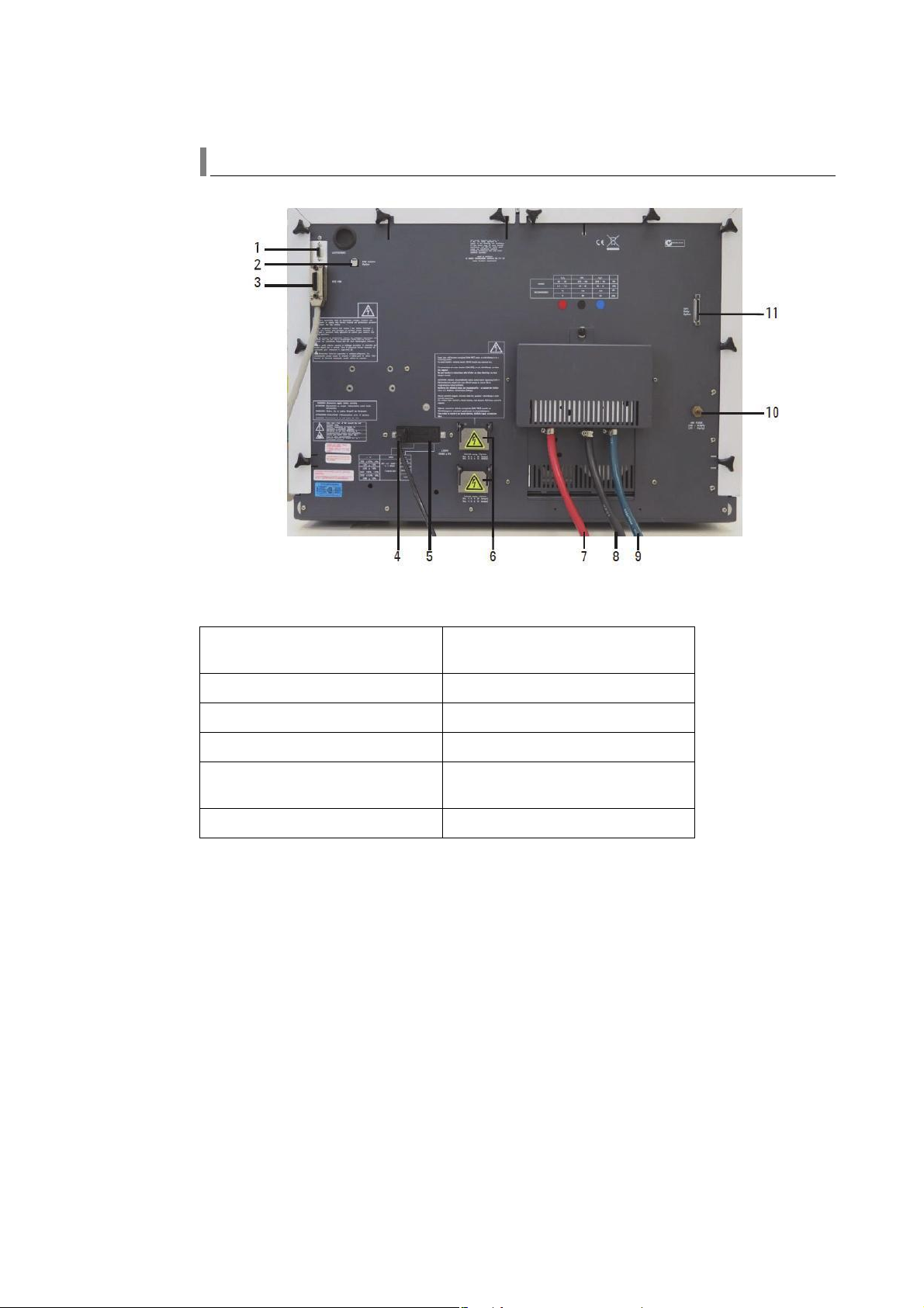
General Information
Flame Instruments Rear View
Where:
1. Serial port for accessories such as the
GTA Viewing/Fume Extraction accessory
2. USB camera cable port 8. Air gas line
3. IEEE 488 cable port 9. N
4. Mains power cable 10. Air purge port
5. Fuse and power setting housing
(CORCOM)
6. UltrAA lamp option ports
7. C2H2 gas line (acetylene)
O gas line (nitrous oxide)
2
11. SIPS pump option port
44 Agilent Confidential 140/240/280 Series AA Service Manual
Page 45
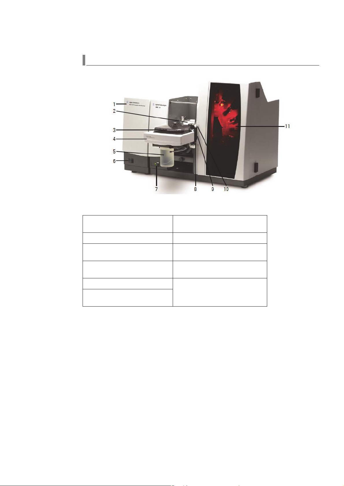
Zeeman Instruments Front View
General Information
Where:
1. GTA 120 Graphite Tube Atomizer 7. Zeeman AA instrument status LED and
power switch
2. Zeeman workhead 8. PSD 120 waste port
3. PSD 120 sample tray (with sample
cover fitted)
4. PSD 120 Programmable Sample
Dispenser
5. Rinse solution 11. Lamp compartment (8 lamps are shown
6. GTA 120 instrument status LED and
power switch
9. PSD 120 rinse tube
10. PSD 120 probe
here - AA280: AA140 and AA240
instruments have 4 lamps.)
140/240/280 Series AA Service Manual Agilent Confidential 45
Page 46

General Information
Zeeman Instrument Rear View
Where:
1. Serial port for accessories such as the
GTA Viewing/Fume Extraction accessory
2. USB camera cable port 9. GTA 120 fuses
3. AA instrument IEEE 488 cable port 10. Water in
4. Mains power cable 11. Water out
5. UltrAA lamp option port 12. Alternate gas inlet, typically nitrogen or
6. UltrAA accessory and fuses 13. Normal gas inlet, typically argon
7. Air purge port 14. GTA 120 IEEE 488 cable port
8. GTA 120 power cable
air
46 Agilent Confidential 140/240/280 Series AA Service Manual
Page 47

Furnace Instruments Front View (D2 - non Zeeman)
General Information
Where:
1. GTA 120 Graphite Tube Atomizer 9. Instrument status LED
2. Workhead (D
3. PSD 120 sample tray 11. PSD 120 waste port
4. PSD 120 Programmable Sample
Dispenser
5. Rinse solution 13. PSD 120 probe
6. GTA 120 instrument status LED and
power switch
7. Flame-off button
8. Flame-on button 15. Burner adjuster
- non Zeeman) 10. AA instrument power switch
2
12. PSD 120 rinse tube
14. Lamp compartment (4 lamps are shown
here - AA240: AA280 instruments have 8
lamps.)
140/240/280 Series AA Service Manual Agilent Confidential 47
Page 48

General Information
Furnace Instruments Rear View (D2 - non Zeeman)
Where:
1. Serial port for accessories such as the
GTA Viewing/Fume Extraction Accessory
2. USB camera cable port 11. Air purge port
3. AA instrument IEEE 488 cable port 12. GTA 120 power cable
4. Mains power cable 13. GTA 120 fuses
5. AA instrument fuse and power setting
housing
6. UltrAA lamp option ports 15. Water out
7. C
gas line (acetylene) 16. Alternate gas inlet, typically nitrogen or
2H2
8. Air gas line 17. Normal gas inlet, typically argon
9. N
O gas line (nitrous oxide) 18. GTA 120 IEEE 488 cable port
2
10. SIPS pump option port
14. Water in
air
48 Agilent Confidential 140/240/280 Series AA Service Manual
Page 49

System Structure and Key Components
The AA instrument is made up of five main components:
• Light sources (Hollow Cathode Lamp, UltrAA Lamp, Continuum-D
• Atomizer (Flame or Furnace or Vapour generator)
• Monochromator (and associated Optics)
• Detector
• Electronics/readout system
General Information
)
2
Light sensitive detector
Electronic readout system
Light source-hollow
cathode lamp
Io
Resonance
Non-resonance
Fill Gas
Figure 2 Main Components of AA Instrument
Monochromator
0.723
It
Atomizer
Resonance
AASVC001
140/240/280 Series AA Service Manual Agilent Confidential 49
Page 50
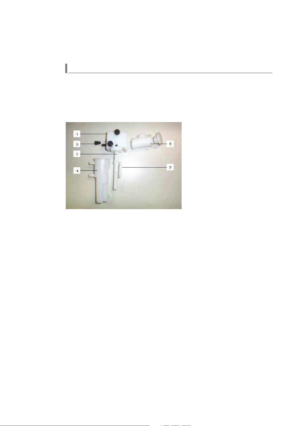
General Information
Sample Introduction
The nebulizer is housed in the nebulizer block which is part of the nebulizer
block/spray chamber assembly and attaches to the side of the burner adjuster. The
following components are connected to the nebulizer block:
• Drain tube
• Liquid trap
• Spray chamber
Nebulizer
Components for the Mk7 Spray Chamber/Nebulizer:
1. Nebulizer block 2. Nebulizer 3. Drain tube
4. Liquid trap 5. Float (captive) 6. Spray chamber
Position the internal capillary to change the uptake rate from 0-8 mL/min. An
adjustable uptake rate can compensate for the fuelling effect of organic solvents. High
vacuum setting greatly reduces the dependence of the uptake rate on liquid level in
the sample container.
The nebulizer uses standard wide bore (0.64 mm I.D.) plastic capillary tubing and can
be used with all types of solutions, including high solids solutions.
Settings
In High Vacuum mode (high sensitivity), the capillary position is adjusted to give
maximum vacuum at the capillary tip, which leads to minimal variation in the uptake
rate with variations in the sample liquid level.
In the High Solids setting, the capillary position is adjusted close to the end of the
venturi throat (this is also the Low Vacuum position). The greater clearance around
the capillary tip reduces clogging caused by solutions with high solids content. It
should be used with wide bore (0.64 mm) plastic capillary tubing, part number
9910024800. The uptake rate at this setting is more sensitive to variation in the
sample liquid level.
50 Agilent Confidential 140/240/280 Series AA Service Manual
Page 51

General Information
WARNING
Maintenance
Nebulizers are factory- checked for optimum sensitivity, uptake rate, and noise
performance.
Performance can be degraded by erosion of internal parts in normal use, by chemical
attack from corrosive solutions, and by dirt. The nebulizer is fully serviceable and can
be repaired by the instrument operator. For additional maintenance information, refer
to the SpectrAA HELP and the User’s Guide.
Nebulizer Block and Impact Bead
The nebulizer block and impact bead assembly are parts of one major assembly. The
nebulizer block and spray chamber fit together with a “twist and lock” action using a
bayonet fitting, and an O-ring to seal the join. The liquid trap is attached to the
nebulizer block with a similar bayonet mount. The liquid trap forms a liquid gas seal
for the spray chamber and drains to waste any excess sample solution which may be
deposited in the mixing chamber.
Figure 3 Impact bead and O-ring
The spray chamber and liquid trap assembly may contain solutions which are flammable, toxic,
corrosive or otherwise hazardous. Such solutions can create fire and explosion hazards and
chemical attack that may cause serious personal injury and damage to property.
Take care when handling the spray chamber and liquid trap. Empty the liquid trap into a suitable
waste disposal system.
140/240/280 Series AA Service Manual Agilent Confidential 51
Impact Bead
The impact bead helps to separate the larger droplets from the sample aerosol. Its
position and adjustment have a significant effect on the sensitivity and noise
performance of the instrument.
Page 52

General Information
NOTE
CAUTION
WARNING
It is possible to set the bead position for a peak sensitivity which exceeds the
spectrometer specification. This may not give the best signal to noise ratio. For normal
operation, you should adjust the position of the bead for more sensitivity, which is
just above instrument specification, then adjust the bead until the absorbance drops 5
– 10%. This will produce a good balance between sensitivity and noise.
If adjustment of the bead position does not change the sensitivity, turn off the flame,
remove the nebulizer block assembly and check the bead adjustment mechanism. If the
bead does not move in and out when you rotate the impact bead adjusting knob, refer
to the online help.
The impact bead position should be optimized for different types of solutions.
Components provided for use with organic solvents should not be used with acidic or alkaline
solutions. Impact beads will be attacked by hydrofluoric acid, so when using this acid use a teflon
bead (part number 9910078900).
Liquid Trap
The user must be trained to clean the liquid trap regularly to prevent any build up of
deposits that could inhibit free movement of the float. Check that the float is free to
move, before you fit the liquid trap to the nebulizer block. The float should be
inserted with its open end down.
The liquid trap has two outlets:
1 The top side outlet which vents toxic fumes away from the instrument (optional).
2 The lower side outlet which drains excess solution from the analysis.
Connect tubing to the drain outlet and place the other end of the tubing in a waste
container. Do not use a glass waste container.
Do not allow the lower end of the drain tubing to drop below the level of the liquid in the waste
container as this may cause a flashback.
52 Agilent Confidential 140/240/280 Series AA Service Manual
Page 53

General Information
NOTE
For organics applications, the drain and vent tubing should be made from organics resistant material (such
as 'Buna-N' tubing).
Spray Chamber
The spray chamber fits to the rear of the nebulizer block assembly with a bayonet
mount. It carries the burner and is closed by the pressure relief bung. Combustible
gases and sample solution are mixed in the spray chamber before passing through the
burner slot for consumption in the flame.
The spray chamber houses the mixing paddle. This paddle is used for applications
where the solutions have high dissolved solids and interferences. It is usually used in
conjunction with the nebulizer set to the High Solids position (see “Nebulizer” on
page 50). The mixing paddle reduces sensitivity by about 30%.
The textured internal surface finish of the spray chamber is easily wetted by sample
liquids. This prevents formation of large droplets which could upset the stability of the
flame and the precision of analytical results.
Do not touch the internal, roughened surfaces of the spray chamber with bare fingers,
as the oils from your skin will prevent good drainage from the spray chamber.
Poor drainage from the spray chamber may cause an unstable flame. Erratic analytical
results and poor signal to noise are good indicators of this. Check that internal
surfaces of the spray chamber are adequately rough and free of dirt, grease, oil, and
obstructions – burrs, deep scratches, and fibres – particularly at the drain outlet. Use
coarse sandpaper to remove these, and then thoroughly brush the internal surfaces
with a concentrated detergent solution.
The spray chamber should be replaced if internal surfaces cannot be cleared of
unwanted deposits. Before refitting the spray chamber, check all O- rings and replace if
necessary to maintain gas seal integrity. Wet the O- rings with distilled water before
assembly.
Burner
Two types of Mark 7 burners are available. Each is designed to suit the characteristics
of permitted gas combinations and is clearly labelled. Each is fitted with a
non- removable plate and a coded interlock pin for identification by the instrument.
Air/acetylene only 210164000
Nitrous oxide/acetylene or air/acetylene 210164100
140/240/280 Series AA Service Manual Agilent Confidential 53
Page 54

General Information
WARNING
You should clean the flame exit slot by using the special cleaning card supplied with the
spectrometer, and following the procedure included with the burner.
The burner is assembled and sealed at the factory. Never disassemble the burner. Leaks can occur
because of improper re- assembly. This can create explosion and fire hazards which can cause
death or serious personal injury and damage to equipment and property.
Burner Deposits
Deposits that build up around the burner slot will alter the flame characteristics.
Carbon deposits can deflect the flame and cause overheating of the burner and
interlock plate, which may melt the spray chamber. This can result in a gas leak and
fire. If the build up is allowed to continue, the static pressure in the liquid trap may
increase to the point where the liquid seal could fail and perhaps cause a flashback.
Deposits can also change the path length of the burner slot, giving wrong results.
54 Agilent Confidential 140/240/280 Series AA Service Manual
Page 55

Figure 4 Altered flame characteristics due to deposit build up.
WARNING
WARNING
A dirty burner can cause a flashback.
General Information
The burner must be cleaned regularly. Special cleaning cards are provided with the
burner. Refer to the online help in the software for a more detailed description. The
burner can be cleaned after removal from the instrument by using the burner cleaning
card and/or a stiff brush to dislodge difficult deposits, while the burner is held under
running water. An ultrasonic cleaning bath with laboratory detergent will also help.
Contact with a hot burner can cause severe burns. Check that the burner has cooled, or wear heat
resistant gloves before handling it. Improper or careless maintenance of burners can create
explosion and fire hazards that can cause serious personal injury and damage to property. Never
allow burners to become blocked.
Always extinguish the flame and turn off all gases before attempting to clean the burner.
Avoiding Burner Deposits
The burner slot has a smoothly polished internal profile to reduce build up of solids,
including salts and carbon. Obstructions which disturb smooth gas flow out of the
burner will increase both salt and carbon build up.
Always check that the burner is clean before starting any analysis. If the slot is clean,
deposits are less likely to occur. Carbon build up is caused by breakdown of acetylene.
It occurs mostly with a nitrous oxide- acetylene flame and is much worse in an
acetylene- rich flame. Carbon will usually build up along the slot, and can block the
slot.
140/240/280 Series AA Service Manual Agilent Confidential 55
Page 56

General Information
Figure 5 Burner with carbon build up (MK6 burner shown here)
These operating procedures will reduce salt deposits:
• Use the maximum sample dilution consistent with acceptable signal to noise ratio.
• Minimize the sample uptake rate by adjusting the impact bead, or by increasing the
• Use microsampling methods.
capillary length, or adjusting the nebulizer.
These operating procedures will reduce carbon deposits:
• Allow the burner to warm up with a lean (low acetylene) flame before setting the
gas flows required by the analysis.
• Use the leanest (low acetylene) possible flame consistent with acceptable signal to
noise ratio.
• Use the maximum total gas flow consistent with the required flame stoichiometry.
Burner Adjuster Assembly
There are three burner adjuster assemblies:
1 The Automatic Gas Control option uses the burner adjuster assembly to house the
acetylene flow needle valve and the acetylene and oxidant flow tubes.
Figure 6 Front face of burner adjuster assembly - AGCU
2 The Programmable Gas Control option does not use the burner adjuster assembly to
house any of the gas controls.
56 Agilent Confidential 140/240/280 Series AA Service Manual
Page 57

General Information
NOTE
Figure 7 Front face of burner adjuster assembly - PGCU
3 The Automatic burner adjuster (ABA) contains a motor drive for vertical adjustment
and a manual drive for horizontal adjustment. Vertical adjustment is controlled by
software.
Figure 8 Automatic burner adjuster
Each of the 3 burner adjusters contain:
• the mechanical drive mechanisms for vertical and horizontal positioning.
The third degree of motion for burner positioning is achieved by rotating the burner using the burner
rotation lever that is part of the burner assembly.
• gas nipple for acetylene/auxiliary oxidant mix
• gas nipple for Primary Oxidant to nebulizer
• Burner interlock microswitches
Burner present (a burner must be fitted before a flame can be ignited)
Burner type (a N
to N
O)
2
O/acet burner must be fitted to permit change of oxidant from air
2
• Pressure Bung relief interlock switch
Pressure relief bung- must be fitted to permit flame ignition
• Liquid trap interlock reed switch
Liquid trap float- position must be correct (trap full) to permit flame ignition
140/240/280 Series AA Service Manual Agilent Confidential 57
Page 58

General Information
The ABA contains additionally
• facility for software controlled Vertical positioning of the burner (using stepper
• burner home opto
motor and drive belt assembly)
Inside the Agilent-AA280 Automatic burner adjuster.
1. Carriage assembly 2. Vertical adjustment gear 3. Horizontal adjustment knob
4. Spacer 5. Vertical adjustment drive motor 6. Drive belt
When an instrument is operated in flame mode, the burner adjuster carries the
burner, nebulizer block, and spray chamber assembly.
In furnace mode, the burner is removed and the nebulizer block and spray chamber
assembly is replaced by the D
(Non Zeeman) workhead.
2
Ignition Interlocks
Four ignition interlock switches are mounted in the burner adjuster. These switches
enable the gas controls and permit flame ignition.
• Burner present–a burner must be fitted before a flame can be ignited.
• Burner type–a N
to N
O.
2
O/acet burner must be fitted to permit change of oxidant from air
2
• Pressure relief bung–must be fitted to permit flame ignition.
• Liquid trap float–position must be correct (trap full) to permit flame ignition.
Optics
The Agilent AA140/240/280 series optics design can include:
• Double beam geometry to ensure baseline stability
• Motorized monochromator, lamp selection, and slit drives to simplify setup and
allow multi- element analyses
58 Agilent Confidential 140/240/280 Series AA Service Manual
Page 59

General Information
• A beam splitter and a Rotating Beam Combiner (RBC) for maximum light
throughput
Monochromator
Agilent AA140/240
The monochromator is a 1/4 meter Czerny- Turner configuration. It uses a
conventional micrometer and sine bar (or radius arm) to rotate the grating. The
micrometer is driven by a micro-stepping stepper motor.
Figure 9 AA 240Z, ¼ m monochromator
Figure 10 AA140/240, ¼ m monochromator
The monochromator drives automatically to a selected wavelength in 0.46 nm/step at a
rate of 4500 steps/min (or 2070 nm/min). When peaking on a spectral line, the
monochromator is driven in microsteps of 0.0036 nm.
One rotation of the micrometer is approximately 23 nm.
Agilent AA280
The monochromator is a 1/3 meter Czerny- Turner configuration. It uses a
conventional micrometer and sine bar (or radius arm) to rotate the grating. The
micrometer is driven by a micro-stepping stepper motor.
Figure 11 Agilent AA280, 1/3m monochromator.
140/240/280 Series AA Service Manual Agilent Confidential 59
Page 60

General Information
The monochromator drives automatically to a selected wavelength in 0.36 nm/step at a
rate of 5625 steps/min (or 2025 nm/min). When peaking on a spectral line, the
monochromator is driven in microsteps of 0.0028 nm.
One rotation of the micrometer is approximately 18 nm.
Peaks are always approached from a higher wavelength to eliminate the effect of
backlash in the mechanism. After peaking at zero order, the monochromator drives to
the specified wavelength and peaks again. If fitted with a D
peaking occurs automatically at power- on.
The processor determines the actual position of the peak by monitoring the output of
the PMT and counting stepper motor pulses. The search range for a peak is
determined by the slit width:
• +/- 0.5 nm for 1 nm slit
• +/- 0.4 nm for all other slits
In the absorbance mode, this peaking process is automatically repeated after any
change of:
• wavelength
• slit width
• lamp type
• lamp current
Peaking on Spectral Lines
lamp then zero order
2
During an automatic run, re- peaking occurs before each re- slope or recalibration.
In Flame Emission mode, the peaking process is initiated by an emission setup
command.
Slits
The slits are selected by a stepper motor which drives the slit to the correct position.
The following slits are in the Agilent 140/240/280:
• 1.0 nm
• 0.5 nm
• 0.2 nm
• 0.1 nm (AA280 only)
• 0.5 nm reduced height
To establish a “home” position during initialization, the slit motor slightly overdrives
the slit plate against the end stop from any slit position. There will be an audible
knock as the slit plate is driven against the optics casting. The number of knocks
depends on the slit position selected when the instrument was last turned off.
To select the desired slit, the instrument counts stepper motor pulses from the “home”
position.
60 Agilent Confidential 140/240/280 Series AA Service Manual
Page 61

Figure 12 Grating and slit plate in a Agilent-AA280.
Background Correction
General Information
Background correction for NON Zeeman instruments is done with a deuterium (D2)
arc lamp. For Zeeman instruments, refer to “Zeeman Technique” on page 636. The
current for the D
lamp is controlled by the processor, but is normally limited to
2
between 100 - 200 mA peak. The current can go down to 60 mA to match very weak
hollow cathode emission lines (e.g. Lead).
The D
and once for the reference beam. The D
lamp signal is measured twice every mains cycle, once for the sample beam
2
current is adjusted based on the reference
2
beam, to compensate for drift.
During Optimization the microprocessor adjusts two parameters so that the sample
channel D
lamp intensity matches the sample channel hollow cathode lamp (HCL)
2
intensity:
1 D
lamp current
2
2 The gain of the PGA for the D
signal
2
The lamp is enclosed in a safety-interlocked housing at the front of the instrument.
Power to the lamp is removed when you remove the D
lamp and panel.
2
Lamp Selection
The Agilent AA140/240/280 instruments are available with either manual or automatic
lamp selection. The lamps’ positions are fixed. They are selected by rotation of the
lamp selection mirror. In an automated instrument a stepper motor rotates the mirror.
In a manual instrument the operator uses a lever to select the lamp.
140/240/280 Series AA Service Manual Agilent Confidential 61
Page 62

General Information
NOTE
Figure 13 The lamp selection mirror from a AA280.
For the Agilent AA280, we recommend that lamps with no graded seal such as Potassium are placed in
alternate positions to lamps with a graded seal such as Copper. This is to prevent the lamps colliding.
Up to four UltrAA lamps can be installed if greater lamp intensity is needed. The
looms for the UltrAA lamps are standard for the AAA280 Zeeman.
The AA280 Zeeman instrument has an internal UltrAA lamp control module for two
lamps which is software controlled. The internal module controls UltrAA lamps in
positions 1 and 3. For additional UltrAA lamps to be powered an external UltrAA
lamp control module (part number 10056900) is needed. The external module controls
UltrAA lamps in positions 5 and 7. The internal UltrAA lamp control module is
available as a factory fitted option for the AA240 Zeeman.
UltrAA lamps can only be fitted to lamp positions 1, 3, 5 and 7 in the AA280 Zeeman.
Figure 14 The eight lamp positions in an Agilent AA280.
Lamp Recognition
Lamps can be identified by a network of two resistors and two diodes in the base of
coded lamps. This circuit allows the instrument to detect the lamp element. Lamps
equipped with lamp recognition circuits have two extra pins and each socket has two
extra connectors to permit the processor to read the lamp identification code.
62 Agilent Confidential 140/240/280 Series AA Service Manual
Page 63

General Information
When a particular element is selected, the spectrometer locates the appropriately
coded lamp in one of the lamp positions. If the required coded lamp cannot be found
the lamp position specified in the method is used.
In an automated system the instrument will automatically drive the lamp select mirror
to select the operating lamp. If uncoded lamps are used, a “Lamp not recognised”
message will be displayed. In a multi-element sequence, the instrument will
automatically recognize the next lamp in the sequence and warm it up at the correct
current regardless of its position. If a coded multi- element lamp is used during an
autorun, the instrument will not pause between elements at method changeover.
Optics Chassis
The optics chassis contains:
• the monochromator
• the mirrors which form the sample and reference beams of light from the hollow
cathode and background correction lamps
• the PMT assembly (mounted directly on the PMT interface PCA)
• the RBC mirror and motor assembly (for dual beam instruments - 240/280)
• the lamp select mechanism
HCL energy enters the optics chassis and hits the lamp select mirror M5. Light reflects
from the lamp select mirror to the beam splitting mirror BS. Fifty-five percent of this
energy passes through the beam splitter and becomes the reference beam hollow
cathode light, the remaining 45% is reflected and becomes the sample beam hollow
cathode light.
The sample beam passes through the sample compartment and is reflected and
focused by toric mirror M4. Light reflected by M4 passes the RBC mirror and strikes
the monochromator entrance mirror M3. The beam will pass the RBC mirror when
blank segments of the disk are in the optical path. Spherical mirror M3 directs the
chopped sample beam through the selected slit and into the monochromator.
The reference beam passes the BS and strikes flat mirror M6. M6 reflects the light to
flat mirror M7, which reflects the light to toric mirror M8. M8 focuses the image and
reflects it onto the RBC mirror. It will be reflected onto M3 and into the
monochromator by the mirrored segments of the RBC.
The light in the reference beam is reflected off three more surfaces than in the sample
beam. To compensate for this loss, the beam splitter is designed to allow more light
(55%) from the hollow cathode lamp into the reference channel, and less light (45%) is
reflected into the sample channel.
D
energy enters the optics chassis and strikes the D2 mirror, M5D2. Light reflected
2
from M5D2 is split into sample and reference beams by the beam splitter. The path is
the same as the light from the hollow cathode lamp.
140/240/280 Series AA Service Manual Agilent Confidential 63
Page 64

General Information
Figure 15 M5D2 mirror assembly and beam splitter.
45% of the D2 light is reflected by the beam splitter into the reference beam and 55%
is transmitted into the sample beam. This means that there is much less D
light in
2
the reference channel than in the sample channel. This does not affect instrument
performance.
Figure 16 Optics layout - Non-Zeeman (D2) Instruments
64 Agilent Confidential 140/240/280 Series AA Service Manual
Page 65
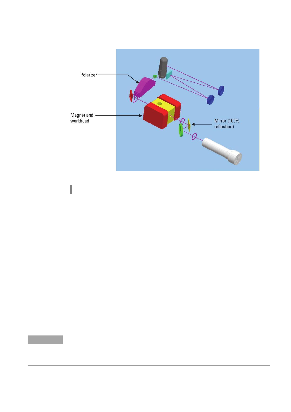
General Information
NOTE
Figure 17 Optics Layout - Zeeman instruments
UltrAA lamp Control Module
The Agilent UltrAA Lamp Accessory is a high- intensity hollow cathode spectral line
source which delivers lower detection limits, increased sensitivity, and improved
calibration linearity.
UltrAA lamp outputs are 3- 5 times greater than a normal hollow cathode lamp.
The sharper emission profile of the UltrAA lamps increases sensitivity up to 40% when
compared with conventional lamps. Lower baseline noise levels and higher sensitivity
lower the detection limits that can be achieved.
The UltrAA lamp control module can power two lamps simultaneously, allowing one
UltrAA lamp to be pre- warmed whilst another is in operation. This reduces "dead"
time during analysis.
Other benefits of UltrAA lamps include:
• Automatic lamp recognition
• Fixed boost current for simple operation
• Improved calibration linearity
• Longer lamp lifetimes with typical lifetimes exceeding 8000 mA hours
A built in UltrAA lamp control is standard on the Agilent- AA280 Zeeman with the
ability to power two UltrAA lamps. An additional UltrAA Lamp Accessory can be
added to provide power to two additional lamps.
For the Agilent AA flame system, only the unboosted section of the UltrAA lamp will be automatically
powered by the instrument. An operator is required to manually strike the boost circuit on the UltrAA lamp
accessory when setting up for an automated run or immediately prior to use. In Zeeman systems, the
software will automatically activate the boost for the two UltrAA lamps connected to the internal supply.
This option is set up in the worksheet.
140/240/280 Series AA Service Manual Agilent Confidential 65
Page 66

General Information
NOTE
The UltrAA Lamp Accessory's unique loom pre-fitted is available on selected Agilent
AA models. The loom is wired to the lamp socket and terminates in a connector on
the instrument’s rear panel, providing the customer with the option to later purchase
and self install the accessory.
Only one connector will be visible on the rear panel of Agilent furnace instruments fitted with the internal
UltrAA lamp module. This connector is provided for an optional UltrAA lamp supply module to power an
additional two UltrAA lamps.
A special retro- fit loom kit must be ordered with the UltrAA Lamp Accessory for
spectrometers already in the field. In this case, the UltrAA Lamp Accessory will
require installation by FSE.
Standard hollow cathode lamps are also functional in both lamp turret positions which
are fitted with the UltrAA lamp wiring, and automatic lamp recognition will remain
operational.
Specifications
Features and Options
• Capability to power two UltrAA lamps simultaneously.
• Automatic lamp recognition.
• Truly independent lamp and boost supply circuits.
• Fixed (non adjustable) boost current supply.
• In built UltrAA lamp supply for two lamps.
• Optional retro- fit kit available for instruments not containing the factory fitted
• Improved lamp lifetimes compared with standard Hollow Cathode lamps.
UltrAA lamp loom.
Electrical Supply
Voltage 100, 120, 220 or 240 VAC ±10%
230 +14% / -6% (using 240V tapping)
230 +6% / -14% (using 220V tapping)
Frequency 50 or 60 Hz ±1 Hz
Power rating 50 VA maximum
Electrical Output (typical)
Boost run current 150 mA +10% / -5%
Boost run voltage 40 VDC ±10 VDC
Boost strike voltage 400 VDC ±60 VDC
Filament voltage 1.2 VDC ±10% (lamp off)
12 VDC ±10% (prior lamp strike)
5 VDC ±10% (lamp run)
Performance:
Lamp lifetime > 5000 mA-hours (based on operating, not boost, current)
Environmental Conditions:
Operating
66 Agilent Confidential 140/240/280 Series AA Service Manual
Page 67

General Information
Altitude 0 to 853 m (0 to 2800 ft)
Temperature 10 to 35°C (50 to 95°F)
Humidity 8 to 80% (non-condensing)
Altitude 853 to 2133 m (2800 to 7000 ft)
Temperature 10 to 25°C (50 to 77°F)
Humidity 8 to 80% (non- condensing)
Storage
Altitude 0 to 2133 m (0 to 7000 ft)
Temperature 5 to 45°C (40 to 115°F)
Humidity 20 to 80% (non-condensing)
Gas Control
Agilent AA140/240/280 series accommodates three levels of gas control:
• No gas control - furnace or cold vapour only
• Automatic gas control unit (AGCU)
• Programmable gas control unit (PGCU)
Programmable Gas Control Unit (PGCU)
Figure 18 PGCU gasbox
The programmable gas control unit (PGCU) also known as the “Hammer Gasbox“ is an
electromechanical assembly that operates under the control of software resident in:
• the instrument FLASH firmware (on main control PCA)
• the PC or controller.
The PGCU uses oscillating armature flow control valves, operating at a set frequency
of 33 Hz, to set the flow rates of fuel and auxiliary oxidant. See the cross section
diagram below.
Flow control is achieved by altering the mark to space (on/off) ratio of the oscillation
frequency. A calibration table (in EPROM) translates a required flow rate into a
mark/space ratio.
The PGCU has an open loop control system. There are no flow sensors and no
feedback. The actual gas flows are dependent on the setting of the pressure regulators
and on the calibration of the flow control valves.
140/240/280 Series AA Service Manual Agilent Confidential 67
Page 68

General Information
NOTE
NOTE
Flame stoichiometry may need to be optimized for elements like chromium which are
sensitive to stoichiometry values.
Figure 19 Flow control valve
When you press the black IGNITE push- button on the instrument front panel:
• all safety interlocks are checked by the instrument
• The air inlet solenoid will open if the interlocks are satisfied
• After the oxidant pressure switch detects pressure in the reservoir, the acetylene
and igniter solenoids are energized, and a narrow tongue of air-enriched acetylene
flame is directed across the burner slot to light the flame
• Air is entrapped in the acetylene flow by the igniter capillary mounting block
• Default ignition gas flow settings are used during the ignition sequence
The igniter assembly consists of a solenoid valve, an igniter nozzle assembly and a spark generator.
Acetylene to the igniter is regulated to 44 kPa (6.3 psi).
• Default ignition gas flows for air and acetylene are changed to the user- specified
stoichiometry (the mix of fuel and air) 2 to 3 seconds after the flame has been
established
If an N2O/acetylene flame has been chosen, changeover will be delayed until after the default
air/acetylene flame has been established and the IGNITE button is released.
Selection of air or N2O oxidant is controlled by the solenoids in each of the incoming
lines. The selected oxidant’s pressure is regulated to a nominal maximum of 210 kPa
(30 psi), passed to the oxidant reservoir and monitored by a low pressure sensor.
Oxidant supply to the nebulizer block follows two paths:
•primary oxidant, a fixed flow through the nebulizer fixed by the back pressure
provided by the nebulizer to around 10 - 11 liters per minute
•auxiliary (secondary) oxidant (and fuel), an adjustable flow which is controlled by
the PGCU under the direction of the PC software
68 Agilent Confidential 140/240/280 Series AA Service Manual
Page 69

General Information
Figure 20 Pneumatic circuit (PGCU)
Gas enters the flow valve through a right angle fitting, flows axially through the
magnetic pole piece of the valve and is modulated by the armature.
The gas leaves the valve body and passes on through the internal plumbing to the
spray chamber connection points.
Acetylene flows through a restrictor and expands into a damping chamber to reduce
flow pulsations which might otherwise create audible flame noise and visible flicker.
Automatic Gas Control Unit (AGCU)
Similar to the programmable gas control unit, the automatic gas control unit controls
flame conditions and ignition. A manually- adjusted needle valve controls acetylene
flow. There is no secondary oxidant flow. There are no oscillating armature flow
valves, and the flows cannot be stored with individual methods. As with the
programmable gas control unit, the primary oxidant flow for the flame is fixed by the
back pressure provided by the nebulizer, and is around 10 - 11 litres per minute.
The needle valve to control fuel flow and the flow meters for both oxidant and fuel
are housed in the burner adjuster assembly.
140/240/280 Series AA Service Manual Agilent Confidential 69
Page 70

General Information
NOTE
NOTE
Figure 21 AGCU burner adjuster
When you press the IGNITE push- button on the instrument front panel, all safety
interlocks are checked by the instrument. The air inlet solenoid will open if the
interlocks are satisfied. After the oxidant pressure switch detects pressure in the
reservoir, the acetylene and igniter solenoids are energized, and a narrow tongue of
air- enriched acetylene flame is directed across the burner slot to light the flame. The
igniter capillary holder entraps air in the acetylene flow. For ignition the user must
also set the fuel needle valve to deliver around 2 L/min fuel to the flame.
The switching of flame types between air/acetylene and N
instrument firmware and the supply solenoids.
The needle valve is not relied upon to stop acetylene flow. The solenoids do this when the flame is turned
off (either by the instrument or the operator). Any gas left in the gas lines after the supply solenoids have
closed will bleed through the spray chamber to the atmosphere.
It is essential the acetylene supply pressure is within the recommended pressure limits as there is no
internal regulator to control the pressure to the igniter. The length of the tongue of flame during ignition is
dependent on the supply pressure.
O/acetylene is controlled by
2
70 Agilent Confidential 140/240/280 Series AA Service Manual
Page 71

General Information
NOTE
For AGCU gas boxes produced after September 1997 the normally open solenoid is closed while the gas
box is in use, and opened only when the flame is turned off, allowing faster discharge of the oxidant
reservoir.
Ignition Interlocks
All interlocks must be satisfied before the PGCU will accept an IGNITE signal. These
interlocks are:
• Spray chamber pressure relief bung in place
• Liquid trap full
• Burner fitted
• Oxidant reservoir pressure - must be less than 155 kPa for ignition then greater
than 155 kPa to maintain the flame
• Flame shield/viewing window in place
• Flame sensed off
To maintain the flame, most of these interlocks must stay satisfied. Exceptions are:
140/240/280 Series AA Service Manual Agilent Confidential 71
Page 72

General Information
NOTE
• Flame shield/viewing window in place. After the flame is established, this interlock
• Flame sensed off. After the flame is established, the monitoring effect of this
The ignition sequence is disabled for a period of 4 seconds following a shutdown of
the flame. This allows any combustible materials which may still be around the sample
compartment to disperse.
The exhaust fan must be operating while a flame is lit.
The oxidant reservoir is an integral part of the gasbox. It is a cylindrical PVC tank,
mounted on the gasbox assembly base plate.
is ignored. This allows the flame shield to be opened.
interlock changes to 'Flame sensed on'. This prevents discharge of a combustible gas
mix from the burner if the flame goes out. It also prevents ignition of a flame if the
sensor is triggered by external light.
Oxidant Reservoir
The function of the Oxidant reservoir is to store a sufficient volume of oxidant, to
quench the flame at any stoichiometry in the event of:
• a normal shutdown
• when any critical interlock is violated
• during mains failure.
When the IGNITE push- button is pressed, the oxidant reservoir is filled with air at
210 kPa. The low pressure sensor at the reservoir is set to switch on or off at any
pressure value between 155 and 190 kPa (22 and 27 psi).
When the 'flame off' signal is sent by any of the interlocks or by the user pressing the
red FLAME OFF push- button:
• the inlet solenoids immediately shut off all gases
• the flow control valves (on the PGCU) open fully
• the oxidant reservoir contents are emptied
• all gases present in the plumbing are rapidly discharged through the spray chamber
The velocity of the discharged gases is higher than the flame burn velocity. As the
acetylene content drops, the flame lifts off the burner and extinguishes.
Specifications
Inlet Gas Supply Pressures
Gas type Recommended Permissible
Acetylene 75 kPa 65 to 100 kPa
(11 psi) (9.5 to 14.5 psi)
Oxidant 350 kPa 245 to 455 kPa
(50 psi) (35 to 65 psi)
72 Agilent Confidential 140/240/280 Series AA Service Manual
Page 73

General Information
NOTE
The only permissible oxidant gases are air and N2O.
Where both oxidant gases are connected, their pressures should be equalized to within
35 kPa (5 psi).
Gas Flow Rates
Mode Acetylene Oxidant
Air/acet 1.5 to 8.0 L/min 11 to 20 L/min
N2O/acet 4.0 to 8.6 L/min 9 to 16 L/min
Air only Not used 11 to 20 L/min
Default flows at changeover 4.0 L/min 13.75 L/min Air, 11 L/min N2O
Default flows for ignition 2.5 L/min 12 L/min
Flow Rate Accuracy
Acetylene From 1.5 to 2 L/min, ± 0.4 L/min
From 2.0 to 8.0 L/min, ±1.0 L/min
Auxiliary oxidant ±1.3 L/min (primary oxidant accuracy is determined by the
nebulizer).
Operating Pressures
Acetylene (PGCU only)
44 ± 4 kPa (6.4 ± 0.6 psi)
Calibrated using an air input at 75 kPa (11 psi) with 'fuel' flow at 8 L/min and
'oxidant' flow at 15 l/min.
Oxidant
210 ± 10 kPa (30.7 ± 1.45 psi)
Calibrated using an air input at 350 kPa (50 psi) and 'oxidant' flow at 13.5 L/min.
Minimum trip pressure is 155 kPa (22.5 psi), activating on reducing pressure.
Maximum recovery pressure is less than 190 kPa (27.5 psi), activating on increasing
pressure.
140/240/280 Series AA Service Manual Agilent Confidential 73
Page 74

Gas Dispersal
Delay
Wait button
release
Idle
Air Only
Start
Air Only
Wait Air
Air Only
Active
Shutdown
Flame Start
Flame Wait
Air
Igniting
Flame Active
Flush
Spraychamber
Flush
Reservoir
INITIALIZE
General Information
Gas Control Unit Flow Diagram
74 Agilent Confidential 140/240/280 Series AA Service Manual
Page 75

General Information
STATE NAMES STATE ACTIONS
WAIT BUTTON RELEASE Waits for IGNITE button to be released.
IDLE Waits for IGNITE button to be pressed.
AIR ONLY START Checks all interlock conditions. If safe, outputs AIR_ONLY_MODE and
GAS_BOX_ENABLE signals to the gas box.
AIR ONLY WAIT AIR Waits for oxid pressure to be reached. Generates an error if interlocks fail or
pressure is not reached in required time.
AIR ONLY ACTIVE Monitors requests for new flow rates. Generates an error if interlocks fail.
Shutdown gas box when required.
FLAME START Checks all interlocks. If safe, outputs FLAME_MODE, AIR-ACET and
GAS_BOX_ENABLE signals to the gas box.
FLAME WAIT AIR Waits for oxid pressure to be reached. Generates an error if interlocks fail or
pressure is not reached in required time.
IGNITING Waits for the flame to be detected and the IGNITE button to be released.
Generates an error if interlocks fail or the flame fails to light.
FLAME ACTIVE Monitors requests for mode change. When a change request is detected,
ACET and OXID flows are set to intermediate change over values. It then
changes to FLUSH SPRAY CHAMBER state. Also monitors and implements
new requested gas flow rates. Generates an error if interlocks fail. Selects
SHUTDOWN state when required.
FLUSH SPRAY CHAMBER Waits until the gas mixture stabilizes, and then adjusts solenoids to select
new OXID and changes to FLUSH RESERVOIR state. Gas flow rates cannot
change during this time. Generates an error if interlocks fail. Selects
SHUTDOWN state when required.
FLUSH RESERVOIR Waits until the new OXID has flushed the old OXID from the reservoir. It then
selects FLAME ACTIVE state. Final gas flow rates are set in FLAME ACTIVE
state. Generates an error if interlocks fail. Selects SHUTDOWN state when
required.
SHUTDOWN Output off signals to the gas box. Clear all timers. Starts the relight delay timer
if required. Sets the flow rates to ignite settings.
GAS DISPERSAL DELAY Waits for the relight delay timer to expire.
140/240/280 Series AA Service Manual Agilent Confidential 75
Page 76

General Information
Accessories
You can add accessories to the instrument to perform furnace operation, automatic
sampling, sample preparation, and vapor phase analysis. You can find information for
these accessories in the service manuals supplied with the accessories.
Some accessories are self- powered and are connected to the host instrument only by
appropriate data cables. Data communications within the Agilent AA system conform
to the IEEE- 488 standard. You can perform external communication using RS232.
Tab l e 3 Compatible accessories
GTA 110 yes
GTA 120 yes yes yes yes STD yes STD
VGA 77 yes yes yes yes yes * yes *
ETC 60 yesyesyesyesyesyesyesyes
Accessory Compatible instrument
50/55 140 240 240G 240FS 240Z 280FS 280Z
SPS-4 *** yes yes yes yes yes yes yes yes
SPS-3 yes yes yes yes yes yes yes yes
SIPS 10 yes yes yes yes yes
SIPS 20 ** yes yes yes yes
ACT-80 yes yes yes yes yes
Ultra lamp loom fitted Factory option. yes Factory
option
* Requires VGA adaptor for Zeeman, ** Requires external PC control, *** SPS-4 requires SpectrAA version 5.3 or
above.
yes yes yes
76 Agilent Confidential 140/240/280 Series AA Service Manual
Page 77

Agilent 140/240/280 Series AA
Service Manual
2
Removal/Installation, Replacement and
Adjustment
Tools and Supplies 79
Main Frame Covers 81
Replacing the Chimney 81
Replacing the Flame Shield/Viewing Window Assembly 82
Replacing the Flame Sample Compartment Front Panel (140/240/280) 82
Replacing the Flame Sample/Burner Compartment Heat Shield 82
Replacing the Left Front Molding/Panel 83
Replacing the Left Side Cover 84
Replacing the HCL Compartment Cover/Door 85
Replacing the Right Side Cover 85
Sample Introduction 88
Replacing the Burner 88
Replacing the Nebulizer Block/Spray Chamber Assembly 90
Replacing the Spray Chamber 91
Replacing the Pressure Relief Bung 92
Replacing the Mixing Paddles 92
Replacing the Liquid Trap 93
Replacing the Nebulizer Block 94
Replacing the Impact Bead 97
Replacing the Burner Adjuster Assembly 99
Replacing the Carriage from AGCU/PGCU Burner Adjuster 101
Replacing the Carriage from Automatic Burner Adjuster 103
Replacing the Ignition Interlocks 108
Optics 109
Replacing the Monochromator 110
Replacing the Slit/Motor Assembly 112
Replacing the Grating Assembly 114
Replacing the Micrometer Assembly 115
Replacing the Collimator Assembly 118
Replacing the Chopper Mirror Assembly 119
Replacing the UltrAA Lamp Module 120
Wavelength Calibration 122
Optical Alignment 125
Beam Balance 139
Beam Coincidence Check 141
Cleaning Mirrors 142
Gas Control Unit 143
Primary Service Position 143
Secondary Service Position 144
Replacing the Gas Control Unit 145
Gas Calibration 147
Flow Measurements 157
Agilent Confidential 77
Agilent Technologies
Page 78

Removal/Installation, Replacement and Adjustment
Leak Checking 162
Electronics 163
Mains Input and Distribution 163
Replacing the Power Cable Inlet Connector (Corcom Module) 163
Replacing the PC Power Module 164
Replacing the Mains Transformer 166
Replacing the Monochromator Interface PCA 168
Replacing the Main Control PCA 169
Replacing the Photomultiplier Interface PCA 172
Replacing the RBA Opto 174
Replacing the Triac Control PCA (Zeeman Instruments) 175
Replacing the SIPS Control and Power Module 177
Replacing the Flame Detector 178
78 Agilent Confidential 140/240/280 Series AA Service Manual
Page 79

Tools and Supplies
The following table lists all tools and kits that are required for component replacement
and adjustment.
Part Number Description Used for ...
110616390 Backlighting Assembly Loom
7210019400 Back Lighting Assembly Optics - backlighting
7210020200 Ball driver, 2.0 mm Optics - beam splitter
7210020400 Ball driver, 2.5 mm Optics - slit motor removal
7210020800 Ball driver, 3 mm Optics - mono collimators
7210027000 Ball driver, 5 mm Optics - mono screws
7210027100 Posidrive offset screwdriver Optics - lamp socket adjustment
7210027200 Spanner, 7 mm, ring and open end Optics - adjustment
7210027300 Dummy grating Optics - micrometer adjustment (140/240)
Removal/Installation, Replacement and Adjustment
7210027400 Optics alignment target Optics -beam alignment
7210027600 Spray chamber, nebulizer disassembly and
assembly tool
7210027700 Venture extraction tool SIS - disassembly and assembly of venturi
7210027800 Back Lighting Assembly bracket Optics - backlighting
7210035100 Lamp select alignment target Optics HCL alignment
7210035500 1 Abs neutral density filter Instrument Validation
9910045600 Gas module field calibration kit (incl. pressure
gauge, tubings, hoses, adapters)
9910053900 Burner Cleaning + Alignment Cards (100/pk) Optical Alignment + Burner Cleaning
9910075000 Kit - 2 Posidrive screwdrivers (No. 1, 2) + 2 wire
insertion tools
5610101400 Copper HC Lamp (coded) Instrument Validation and Troubleshooting
9910031200 Electrode extractor tool, GTA-D2 GTA D2 workhead
9910033300 Shroud removal tool, GTA-D2 GTA D2 workhead
9910049300 Zeeman electrode extractor tool GTA Zeeman workhead
9910050400 Zeeman Shroud removal tool GTA Zeeman workhead
7210034200 Shroud/tube alignment pin tool GTA workhead
SIS - disassembly and assembly of nebulize
GasBox - Calibration and Troubleshooting
General
210164100 N20/Acetylene burner Instrument Validation and Troubleshooting
6610030100 Test solution - 5ppm Cu (ICP-OES Wavecal soln
500mL)
5190-7001 Test solution - Blank Instrument Validation and Troubleshooting
5190-8279 Copper, 1000 ug/ml, 100ml Instrument Validation and Troubleshooting
9910108300 IQ-OQ Certification Kit IQ-OQ Certification
Instrument Validation and Troubleshooting
140/240/280 Series AA Service Manual Agilent Confidential 79
Page 80

Removal/Installation, Replacement and Adjustment
Part Number Description Used for ...
NA Keysight U1231A True RMS 6000 Count
Handheld Digital Multimeter
(Keysight Technologies, Inc)
NA Keysight U1193A Handheld Clamp Meter
(Keysight Technologies, Inc)
NA Keysight U1168A Standard Test Lead Kit (with
19-mm and 4-mm probe tips)
(Keysight Technologies, Inc)
NA Keysight DSO3202A Oscilloscope
(Keysight Technologies, Inc)
NA TIF CGD880 Gas Leak Detector
(TIF Instruments, Inc)
Not orderable.
Not orderable.
Not orderable.
Not orderable.
Not orderable.
80 Agilent Confidential 140/240/280 Series AA Service Manual
Page 81

Main Frame Covers
Flame shield/Viewing
window assembly
Flame sample
compartment front
panel
Flame sample/Burner compartment heat shield
When removing the AA instrument covers for flame instruments, start with the
Chimney, followed by the Flame shield/Viewing window assembly and the Flame
sample/Burner compartment heat shield. Once these have been removed, you can
remove the Left side cover and/or the Right side cover.
Removal/Installation, Replacement and Adjustment
Replacing the Chimney
The flame AA chimney allows air/gas to flow from the burner through to the exhaust
system. It also helps to block ambient light from entering the SIS compartment and
falsely triggering the flame sensor.
Removal
To remove the chimney, lift it up and off the instrument (there are no screws securing
the chimney).
Installation
Install the chimney in the reverse order of removal making sure the warning messages
are facing the operator (front of instrument).
140/240/280 Series AA Service Manual Agilent Confidential 81
Page 82

Removal/Installation, Replacement and Adjustment
NOTE
Replacing the Flame Shield/Viewing Window Assembly
The Flame shield/Viewing window assembly hinges onto the front of the sample
compartment and is designed to reduce heat and radiation hazards from the flame. An
interlock prevents you from igniting the flame unless the flame shield is closed.
Always fit the flame shield before using your Agilent AA, and leave it closed unless
you need access to the burner.
Removal
1 Remove the chimney (if fitted).
2 Lift the flame shield up and unhook it from the front of the sample compartment.
Installation
1 Hook the flame shield onto the bar at the top of the sample compartment.
2 Lower the flame shield until it rests on the stainless steel bosses on either side of
the sample compartment.
3 Ensure that the metal tongue of the shield engages but does not dislodge or damage
the interlock switch arm.
Videos of the Flame shield/Viewing window assembly are included in SpectrAA help.
Replacing the Flame Sample Compartment Front Panel (140/240/280)
The sample compartment front panel is designed to reduce heat and radiation hazards.
Always fit this panel before using your flame instrument.
Removal
Lift the panel up and free of the burner lugs.
Installation
1 Align the panel so that the 2 holes in the lip of the panel fit over the 2 lugs on the
top of the burner adjuster.
2 Lower the panel so that the burner lugs hold it in position.
Replacing the Flame Sample/Burner Compartment Heat Shield
Removal
1 Remove the chimney (if fitted).
2 Remove the Flame shield/Viewing window assembly (if fitted).
3 Remove the Flame sample compartment front panel (if fitted).
4 Unscrew (loosen) the two screws holding the heat shield in place.
82 Agilent Confidential 140/240/280 Series AA Service Manual
Page 83

Removal/Installation, Replacement and Adjustment
5 Remove the heat shield by lifting it up and out of the sample compartment.
Installation
Install the Flame sample/Burner compartment heat shield in the reverse order of
removal.
Replacing the Left Front Molding/Panel
Removal
1 Push the panel up by applying pressure at the bottom of the panel.
2 Once free of the holding stub lift off the panel.
Installation
1 Place the cover support notch (top rear portion of the panel) over the holding stub.
2 Push the panel firmly down over the stub.
3 Press the bottom of the panel in toward the instrument body to secure it into
position.
140/240/280 Series AA Service Manual Agilent Confidential 83
Page 84

Removal/Installation, Replacement and Adjustment
Holding Stub
Support Notch
Replacing the Left Side Cover
The Left side cover is the same for all 140/240/280 instruments.
Removal
1 Remove the chimney (if fitted).
2 Remove the Flame shield/Viewing window assembly (if fitted).
3 Remove the Flame sample compartment front panel (if fitted).
4 Remove the Flame sample/Burner compartment heat shield (if fitted).
5 Remove the Left front molding/panel (if fitted).
6 Remove the 4 screws from the compartment.
7 Remove the 5 screws from the front edge of the cover.
8 Remove the 5 knob screws from the back edge of the cover (rear of instrument).
9 Lift the Left side cover free of the instrument (It may be necessary to apply some
pressure to free the lower part of the cover from the retaining clips).
Installation
Install the Left side cover in the reverse order of removal while noting the following
points.
1 Secure the knob screws (rear of instrument) in the sequence indicated in the photo.
2 Loosely tighten the screw shown in the green circle, tighten the remaining 3 screws,
and then fully tighten the screw shown in the green circle.
84 Agilent Confidential 140/240/280 Series AA Service Manual
Page 85

Removal/Installation, Replacement and Adjustment
Screw 3
Screw 1
Screw 2
Screw 4
Screw 5
Left side cover retaining clips
Replacing the HCL Compartment Cover/Door
Removal
1 Partially open the Hollow cathode lamp compartment cover/door.
2 Lift up to remove the cover/door from the top and bottom hinges.
Installation
Install the HCL compartment cover/door in the reverse order of removal.
Replacing the Right Side Cover
The Right side cover is the same for 140/240 instruments but 280 instruments have an
extended top portion to accommodate the extra 4 Hollow cathode lamp positions.
Removal
1 Remove the chimney (if fitted).
2 Remove the Flame shield/Viewing window assembly (if fitted).
3 Remove the Flame sample compartment front panel (if fitted).
4 Remove the Flame sample/Burner compartment heat shield (if fitted).
5 Remove the HCL compartment cover/door (if fitted).
140/240/280 Series AA Service Manual Agilent Confidential 85
Page 86
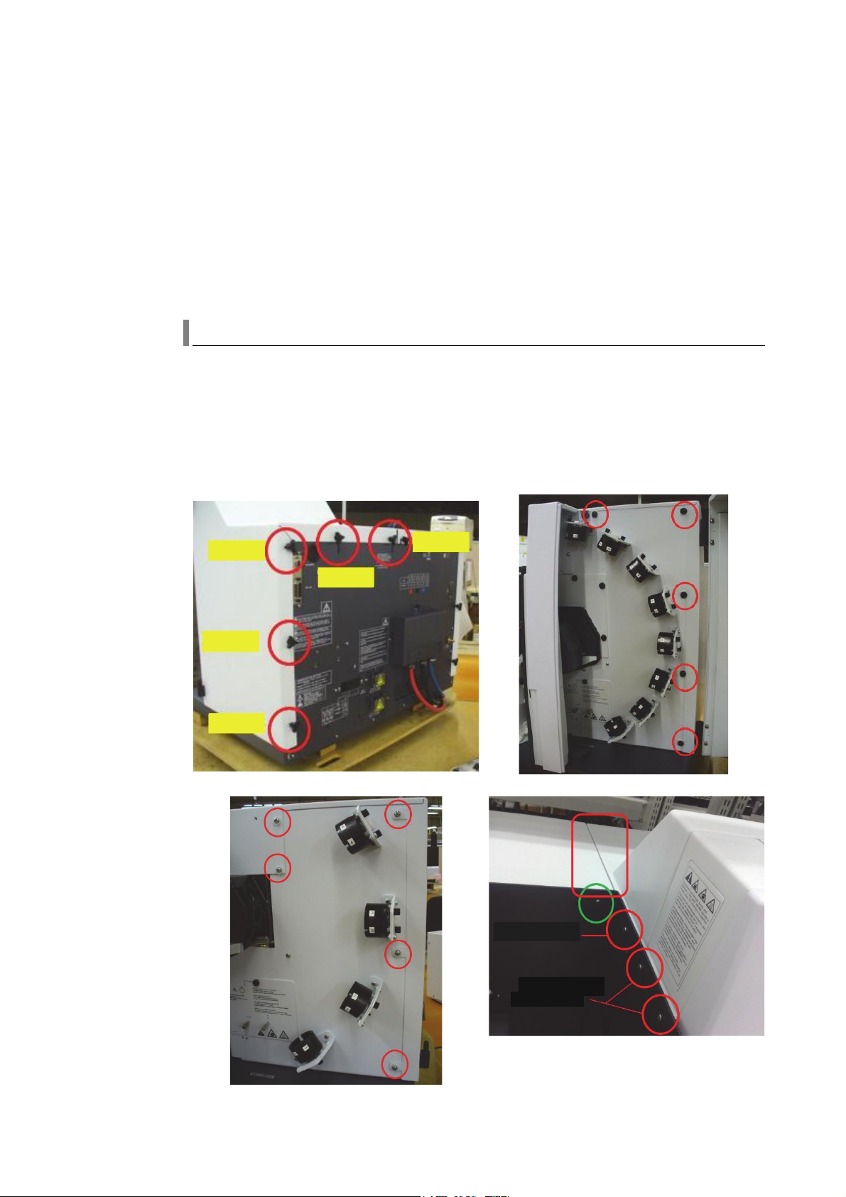
Removal/Installation, Replacement and Adjustment
Screw 1
Screw 2
Screw 3
Screw 4
Screw 5
Remove this screw
No need to remove
these screws
6 Remove the screw in the SIS/burner compartment (see the photo).
7 Remove the 5 black screw-caps on the front of the cover (A small blade screw
driver may be required to pry the caps free).
8 Remove the 5 screws plus the screw cap mounts on the front of the cover.
9 For 140/240 instruments - remove the door magnet (see the photo).
10 Remove the 5 knob screws from the back edge of the cover (rear of instrument).
11 Lift the Right side cover free of the instrument. You may need to apply some
pressure to free the lower part of the cover from the retaining clips.
Installation
Install the Right side cover in the reverse order of removal while noting the following
points.
1 Secure the knob screws (rear of instrument) in the sequence indicated in the photo.
2 Make sure the cover is flat (red rectangle in photo). If it is not flat, loosen the
screws (green circle in photo), and then adjust the cover until it is flat and then
re- tighten the screws.
86 Agilent Confidential 140/240/280 Series AA Service Manual
Page 87

Removal/Installation, Replacement and Adjustment
Magnet
Screw cap fitted
140/240/280 Series AA Service Manual Agilent Confidential 87
Page 88

Removal/Installation, Replacement and Adjustment
WARNING
Sample Introduction
Access to SIS components involves removal of the burner and nebulizer block/spray
chamber assembly from the SIS area/compartment of the instrument. The following
section details the recommended removal and separation processes.
Replacing the Burner
Agilent flame AA 140/240/280 instruments currently use Mark7 burners. You can use
two types of burners:
• Air/Acetylene
• Nitrous- Oxide/Acetylene
Removal and replacement procedures are the same for both types of burner. SpectrAA
Help contains videos for burner removal and replacement.
Removal
Personal Injury Hazard
The burner may be very hot. Always use protective gloves to handle burners.
1 Remove the chimney.
2 Remove the Flame shield/Viewing window assembly.
3 Remove the Flame sample compartment front panel.
88 Agilent Confidential 140/240/280 Series AA Service Manual
Page 89

Removal/Installation, Replacement and Adjustment
WARNING
NOTE
4 Remove the burner from the spray chamber by lifting the burner assembly directly
up. You may need to twist slightly as you lift.
Installation
1 Check the o- ring on the burner. It must be supple, free from nicks or cracks, and
not flattened.
2 Position the burner in the sample compartment with the slot along the optical path
and the plate with the warning towards the front of the instrument.
3 Align the interlock pin with the guide in the burner adjuster.
4 Lower the burner so that the interlock pin enters the guide in the burner adjuster
and the burner neck enters the hole for the burner in the spray chamber.
5 Using a slight twisting motion, push the burner down as far as it will go.
Explosion Hazard
Ensure that the burner is firmly pushed down in the spray chamber. The neck of the burner and its
o-ring should be completely inside the spray chamber, and not visible. This will seal the spray
chamber, so that the combustible gases will emerge only through the burner slot.
You should now align the burner.
140/240/280 Series AA Service Manual Agilent Confidential 89
Page 90

Removal/Installation, Replacement and Adjustment
Replacing the Nebulizer Block/Spray Chamber Assembly
The Nebulizer block/Spray chamber assembly consists of four major
components/systems:
a Nebulizer block (items 1 and 2 in the following photo)
b Liquid trap (items 3, 4, and 5)
c Spray chamber (items 6 and 7)
d Pressure relief bung (item 8)
Components for the Mk7 Nebulizer block/Spray chamber assembly:
1. Nebulizer block 2. Nebulizer adjustment screw + locking screw 3. Drain tube 4. Liquid trap
5. Float (captive) 6. Spray chamber 7. Mixing paddles 8. Pressure relief bung
Removal
1 Remove the Chimney.
2 Remove the Flame shield/Viewing window assembly.
3 Remove the Flame sample compartment front panel.
4 Remove the burner.
5 Remove drain tubing from the lower barb of the liquid trap body.
6 Remove venting tubing from the upper barb of the liquid trap body (if fitted).
7 Loosen both of the knurled retaining screws that secure the nebulizer block/spray
chamber assembly into position on the side of the burner adjuster.
8 Pull the Nebulizer block/Spray chamber assembly directly outward from the burner
adjuster.
90 Agilent Confidential 140/240/280 Series AA Service Manual
Page 91

Removal/Installation, Replacement and Adjustment
NOTE
Nebulizer block/Spray chamber assembly
pulled away from the Burner adjuster
To p
Front
Bottom
Rear
Nebulizer block: Orientation
Installation
Install the Nebulizer block/Spray chamber assembly in the reverse order of removal
while noting the following points.
1 Ensure the gas supply nipple O- rings (labeled 1 in photo) are supple, free from
nicks or cracks, and not flattened.
2 Place the Nebulizer block/Spray chamber assembly in position so that the fuel and
oxidant outlet nipples on the Burner adjuster are engaged in the fuel and oxidant
ports on the nebulizer block.
3 Push the Nebulizer block/Spray chamber assembly firmly onto the nipples of the
Burner adjuster.
4 Tighten the knurled retaining screws alternately (one turn each at a time) so that
the Nebulizer block/Spray chamber assembly is pulled up evenly into place. Tighten
both screws firmly with the fingers only.
Replacing the Spray Chamber
The Spray chamber is designed to promote thorough mixing of aerosol and gases for
the burner, and provide unrestricted drainage to the liquid trap. It attaches directly to
the Nebulizer block/Spray chamber assembly.
Touching or otherwise contaminating any part of the inside surface of the spray
chamber or mixing paddles will degrade the performance of the instrument. It is
recommended that gloves be worn while working with the spray chamber to avoid
contamination.
Removal
1 Using a counter- clockwise (with respect to the mating surfaces) twisting motion
turn the spray chamber 90
to the nebulizer block.
2 Once the bayonet mount has unlocked lift the spray chamber away from the
nebulizer block.
The spray chamber can be removed from the nebulizer block without removing the Nebulizer block/Spray
chamber assembly from the burner adjuster if required.
° to unlock the bayonet mount joining the spray chamber
140/240/280 Series AA Service Manual Agilent Confidential 91
Page 92

Removal/Installation, Replacement and Adjustment
Installation
1 Ensure the O- ring in the rear section of the nebulizer block (B in photo) is supple,
free from nicks or cracks, and not flattened.
2 Position the front end of the spray chamber into the rear end of the nebulizer
block.
3 Using a clockwise (with respect to the mating surfaces) twisting motion as you push
the spray chamber into the nebulizer block, turn the spray chamber 90
bayonet mount firmly joining the spray chamber to the nebulizer block.
° to lock the
Replacing the Pressure Relief Bung
The Pressure relief bung (sometimes referred to as the Spray chamber bung) is part of
the flame AA safety interlock system. It must be fitted before flame ignition is allowed
by the interlock system. The Pressure relief bung closes off the spray chamber and
provides a point of least resistance for any pressure build- up in the rare event of a
flashback.
Removal
Pull the Pressure relief bung from the rear of the spray chamber. This may require a
slight twisting motion to assist movement.
Installation
1 Ensure the O- ring of the Pressure relief bung is supple, free from nicks or cracks,
and not flattened.
2 Wet the O- ring of the Pressure relief bung with distilled water to lubricate it.
3 Insert the Pressure relief bung into the rear of the spray chamber and push it
firmly into position as far as it will go using a slight twisting motion.
Replacing the Mixing Paddles
The Mixing paddles fit into the center of the spray chamber. They remove the larger
aerosol droplets, which can cause photometric noise and burner blockage.
One end of the Mixing paddles has a boss (or knob) at the center of the blades. At the
other end three of the blades have small bumps on their edges. When installing the
Mixing paddles, the boss end goes to the front of the spray chamber. The bumps hold
the paddles in position.
Touching or otherwise contaminating any part of the inside surface of the spray
chamber or mixing paddles will degrade the performance of the instrument. It is
recommended that gloves be worn while working with the spray chamber to avoid
contamination.
92 Agilent Confidential 140/240/280 Series AA Service Manual
Page 93

Removal/Installation, Replacement and Adjustment
NOTE
Removal
1 Remove the spray chamber from the nebulizer block.
2 Remove the Pressure release bung.
3 Push the paddle back through and out of the spray chamber using a blunt, inert,
and clean object (for example, a plastic stirring rod).
Installation
1 Position the boss end of the Mixing paddles in the opening at the rear of the spray
chamber. Align the blades so that an opening between any two of the front blades
is at the bottom of the spray chamber.
2 Slide the paddles into the spray chamber until the rear paddle is about to enter the
hole.
3 Check that the paddles are still positioned as described in step 1 above, then
carefully push the back paddle into the spray chamber using a blunt, inert, and
clean object (for example, a plastic stirring rod) until the paddles are stopped by
the shoulder.
For higher analyte sensitivity, operate the spray chamber without Mixing paddles. For best performance
with samples containing a high level of dissolved solids, use the Mixing paddles.
Replacing the Liquid Trap
The Liquid trap allows excess solution to be drained from the spray chamber. It has
been designed to provide a gas seal under all normal operating conditions with
solutions having a specific gravity greater than 0.75.
Components of the liquid trap include:
• A drain tube which is a plastic tube that screws into the bottom of the nebulizer
block.
• A float containing a magnet (permanently attached - captive - to the drain tube).
• A liquid trap body which connects directly to the nebulizer block with a bayonet
mount.
The drain tube facilitates drainage of waste solution into the liquid trap body. It
should be inspected regularly to ensure it is clean and free of blockages.
The magnet in the captive float works together with the reed switch in the burner
adjuster to form the liquid trap interlock function.
The liquid trap body is designed to capture and hold a set amount of liquid/waste
allowing excess to drain away to a waste vessel via tubing attached to its lower barb.
The upper barb is provided to facilitate safe removal (venting) of vapors which may
result from organic or toxic solutions if used.
Removal
1 Remove the Nebulizer block/Spray chamber assembly from the burner adjuster.
2 Rotate the liquid trap body 90
with the nebulizer and impact bead adjustment knobs. This will disengage the
bayonet mount.
140/240/280 Series AA Service Manual Agilent Confidential 93
°, aligning the two vent barbs of the liquid trap body
Page 94

Removal/Installation, Replacement and Adjustment
WARNING
3 Remove the liquid trap body by pulling it downward free of the nebulizer block the
drain tube and captive float. Be careful not to spill the liquid contents of the liquid
trap body.
4 Remove the drain tube and captive float by unscrewing the drain tube from the
bottom of the nebulizer block.
Installation
1 Screw the drain tube firmly into the bottom of the nebulizer block.
2 Hold the Nebulizer block/Spray chamber assembly so that the float falls down and
rests on the retaining of the drain tube.
3 With the two vent barbs of the liquid trap body aligned with the nebulizer and
impact bead adjustment knobs, lower the drain tube into the trap, ensuring that the
float drops into the space between the two ribs on the inner face of the liquid trap
body.
4 Push the trap upward and then twist it 90
into position.
Replacing the Nebulizer Block
° clockwise to lock the bayonet mount
In addition to providing a mounting facility for the spray chamber and liquid trap, the
Nebulizer block contains input ports for the fuel and oxidant gases, the nebulizer, and
the impact bead.
Fuel and oxidant gases are routed through the nebulizer block to the spray chamber.
The sample is drawn through the nebulizer and onto the impact bead on its path
through to the spray chamber.
Disassembling the Nebulizer
Incorrect nebulizer assembly and fitting in an atomic absorption spectrometer can create
explosion hazards and fire hazards which can cause serious personal injury and damage to
property. Incorrectly assembled parts of the nebulizer may be ejected at high speed. Never
dismantle a nebulizer while the flame is burning.
Check that the nebulizer is correctly assembled and is properly adjusted as described in the
Operation Manuals. Gas connections should be tested and any leaks fixed before lighting the
flame.
The nebulizer is used to break up solutions into small aerosol droplets. Follow the
steps below to take apart the nebulizer. As you do so, carefully inspect all components
for wear and corrosion. Replace all faulty items. If the nebulizer is blocked, clean it as
described in the next section.
94 Agilent Confidential 140/240/280 Series AA Service Manual
Page 95

Removal/Installation, Replacement and Adjustment
NOTE
Nebulizer components:
1. Nebulizer adjustment knob 2. Locking ring 3. Clamp bush guide
4. Capillary assembly 5. O- ring, 1/32 ID x 3/32 OD x 1/32"
6. Spring 7. O- ring, 3/16 ID x 5/16 OD x 1/16"
8. Capillary guide 9. O- ring, 3/16 ID x 5/16 OD x 1/16"
10. Venturi
1 Remove the nebulizer adjustment knob and locking ring by unscrewing the knob in
a counter- clockwise direction.
2 Using the narrow end of the nebulizer tool (part number 7210027000), unscrew the
clamp bush guide and carefully remove it from the nebulizer body.
3 Remove the capillary assembly and the spring.
4 Before you remove the venturi, you must move the impact bead sideways, away
from the venturi. To do this, slacken the clamping screw that secures the impact
bead in the nebulizer block, and move the impact bead to the side.
5 Push the venturi from the rear through the nebulizer body (using the plastic tool
(part number 7210027700)) to dislodge the capillary guide. The capillary guide
should drop out.
6 Finally, extract the venturi from the nebulizer body.
If you need to replace the white plastic threaded insert that the nebulizer adjustment knob and clamp bush
guide screws into because the threads have been stripped, unscrew the insert using the other end of the
tool you used in step 2 above. Refer to “Service Parts” on page 321 for ordering information.
Instructions for disassembly, parts replacement, and performance optimization can also
be found in the SpectrAA online help. You can clean the nebulizer parts by soaking
them for 10 minutes in an ultrasonic bath containing a dilute detergent.
Cleaning a Blocked Nebulizer
1 Remove the nebulizer, disassemble it and check it as described previously.
2 Place the nebulizer in an ultrasonic cleaner containing 0.5% liquid detergent
solution such as Triton X- 100 for 5 to 10 minutes.
3 If the ultrasonic bath fails to clear the blockage, pass a burr- free nebulizer cleaning
wire (some are supplied with the nebulizer) carefully through the nebulizer, and
then repeat the ultrasonic cleaning procedure.
4 Rinse the nebulizer in distilled water, and then allow to dry.
140/240/280 Series AA Service Manual Agilent Confidential 95
Page 96

Removal/Installation, Replacement and Adjustment
WARNING
NOTE
5 Check for a blockage at the junction between the plastic capillary tubing and the
nebulizer capillary. If there is a blockage there, either cut off the clogged section of
plastic capillary or fit a new piece.
Cut off only the required amount of the plastic tubing that is required to remove the
blockage. Excessive shortening of the tubing will increase the uptake rate. After
cutting off the clogged section, it may be necessary to ‘flare’ the end of the capillary
before it can be fitted to the nebulizer. You can do this with a heated needle.
Reassembling the Nebulizer
Incorrect assembly of nebulizers and incorrect fitting of nebulizers to an atomic absorption
spectrometer can create explosion hazards and fire hazards which can cause serious injury to
personnel and damage to equipment and property.
If you are going to fit a new venturi, you should also replace all O-rings.
If you are going to fit a new capillary, you should also fit a new capillary guide and
spring.
If you have to replace any of the O- rings, replace them all. You should always replace
O- rings as a set.
If you are using organics, ensure you fit the organic O-ring kit.
If you have to replace the white plastic threaded insert that the nebulizer adjustment
knob and clamp bush guide screws into because the threads have been stripped, use
the nebulizer tool (part number 7210027000) to remove the old one and fit a new one.
Refer to “Service Parts” on page 321 for ordering information.
To reassemble the components of the nebulizer:
1 Hold the nebulizer block front end up.
2 Place the venturi into the nebulizer body, thin end first (use the plastic tool
provided to push the venturi in as far as it will go).
3 Place the capillary guide into the nebulizer body, with the O- ring end up.
4 Place the spring in the nebulizer body.
5 Carefully insert the capillary assembly, O- ring end first, through the spring in the
nebulizer body.
6 Put the bush, thread end first, in the nebulizer body and screw it in until it stops
using the tool provided. Do not over- tighten.
7 Carefully guide the locking thimble and ring over the capillary and screw it onto
the nebulizer body. You may need to push it in against the spring before the
threads will catch.
96 Agilent Confidential 140/240/280 Series AA Service Manual
Refer to “Replacing the Impact Bead” for instructions on removing, replacing, and
adjusting the impact bead.
Page 97

Removal/Installation, Replacement and Adjustment
WARNING
Replacing the Impact Bead
The impact bead helps to break up larger droplets from the sample aerosol. Its
position and adjustment have a significant effect on the instrument's sensitivity and
noise performance. Two types of impact beads can be used in Agilent AA flame
instruments:
• Glass - for general use
• PTFE - for use with HF
Removal
1 Remove the Nebulizer block/Spray chamber assembly from the burner adjuster.
2 Remove the liquid trap body and the drain tube with captive float.
3 Remove the spray chamber and pressure relief bung.
4 Turn the impact bead adjuster clockwise until the holder comes up against the stop.
The impact bead should then be as close as possible to the end of the nebulizer.
5 Access the impact bead locking screw from the drain hole which is exposed by
removing the drain tube.
6 Turn this screw twice to loosen it.
Nebulizer block:
1. Flat-blade screw driver 2. Clamping screw 3. Impact bead adjuster block
7 Remove the impact bead. If it is not broken and there are no pieces of broken bead
left in the adjuster block, go to step 13. If it is broken go to step 8.
This procedure may dislodge small fragments of glass. To protect the eyes from flying pieces of
glass, protective eye wear should always be worn when performing this procedure.
8 Locate the stainless steel screw on the gas inlet side of the nebulizer block that
locks the impact bead adjusting screw. Loosen this approximately four turns.
140/240/280 Series AA Service Manual Agilent Confidential 97
Page 98

Removal/Installation, Replacement and Adjustment
Gas inlet side of the nebulizer block:
1. Trapping screw 2. Impact bead adjuster
9 Unscrew the impact bead adjuster screw and remove it from the front of the
nebulizer block. It should come out as it is unscrewed. If it does not, loosen the
screw identified in step 8 until it does.
10 Using a probe approximately 3 mm in diameter and at least 100 mm long, push the
remains of the broken impact bead out from the front of the nebulizer block and
dispose of them.
11 If required you can remove the impact bead adjusting screw from the nebulizer
block. Locate the plastic screw on the side of the nebulizer block and loosen it 2- 3
turns. Shake the nebulizer block and the adjusting block should fall out easily.
Replace the parts in the reverse order of removal.
12 Replace the impact bead adjuster screw and screw it into the impact bead adjuster
block until it is firm. Tighten the stainless steel screw identified in step 8 until the
impact bead adjuster screw is located positively, but is still free to rotate
comfortably.
98 Agilent Confidential 140/240/280 Series AA Service Manual
Page 99

Removal/Installation, Replacement and Adjustment
NOTE
NOTE
Nebulizer block
1. Impact bead adjuster block 2. Impact bead adjuster
The impact bead adjuster block must be positioned as close as possible to the front of the nebulizer block.
This must be done to avoid breaking the impact bead after installing a new bead.
13 Fit a new bead. Space the bead away from the end of the nebulizer so that there is
only a small gap of about 0.5 mm between the end of the venturi and the bead.
14 Tighten the impact bead locking screw (loosened in step 5).
15 Check that the impact bead adjuster successfully moves the bead in and out.
16 Reassemble the drain tube, liquid trap, nebulizer block/spray chamber assembly and
re- install it into the burner adjuster.
17 Test operation.
Replacing the Burner Adjuster Assembly
Removal
The burner adjuster assembly must be removed from the instrument to access internal
components. You will need to move the gas control assembly to its primary service
position (see “Gas Control Unit” on page 143) to remove the burner adjuster assembly.
Replace the parts in the reverse order of the following removal instructions.
1 Switch off the instrument.
2 Shut off all gases.
3 Remove the burner and the nebulizer block/spray chamber assembly.
4 Move the gasbox to the primary service position as described in “Gas Control
Unit” on page 143.
5 Disconnect the igniter electrically from inside the gasbox. This is to prevent
accidental ignition or electric shock.
6 Disconnect the Swagelok fitting for the fuel/auxiliary oxidant hose at the top of the
fuel damper cylinder. Access is from the top of the gasbox.
The fuel/auxiliary oxidant hose has a loop in it to allow free horizontal and vertical movement of the
burner adjuster assembly. You must retain this loop when you re-assemble the adjuster.
140/240/280 Series AA Service Manual Agilent Confidential 99
Page 100

Removal/Installation, Replacement and Adjustment
WARNING
7 Disconnect the oxidant hose at the oxidant reservoir. While the gasbox is suspended
in the primary service position you can access the oxidant swagelok connection
from below.
8 Disconnect the Molex plug connecting the interlock loom to the gas control unit
loom.
9 Remove the four screws holding the burner adjuster assembly to the left side of the
gas box bracket, and remove the adjuster assembly complete.
The burner adjuster is heavy (3 kg). It may cause injury or damage if it falls during the removal
and replacement procedure.
Installation
Install the burner adjuster assembly in the reverse order of removal.
100 Agilent Confidential 140/240/280 Series AA Service Manual
 Loading...