

Page 1
User and Service Guide
Publication number 01144-97001
September 2002
For Safety and Regulatory information, and publishing information, see the pages
at the back of this book.
© Copyright Agilent Technologies Company 1993-2002
All Rights Reserved.
1144A Active Probe
Page 2

Contents
Specifications 4
Characteristics 4
General Characteristics 5
Operating the Probe 6
Probe Power Connection 8
Cleaning the Probe 8
Service Strategy 8
To return the probe for service 9
Calibration Testing Procedures 9
Calibration Test Record 14
2
Page 3

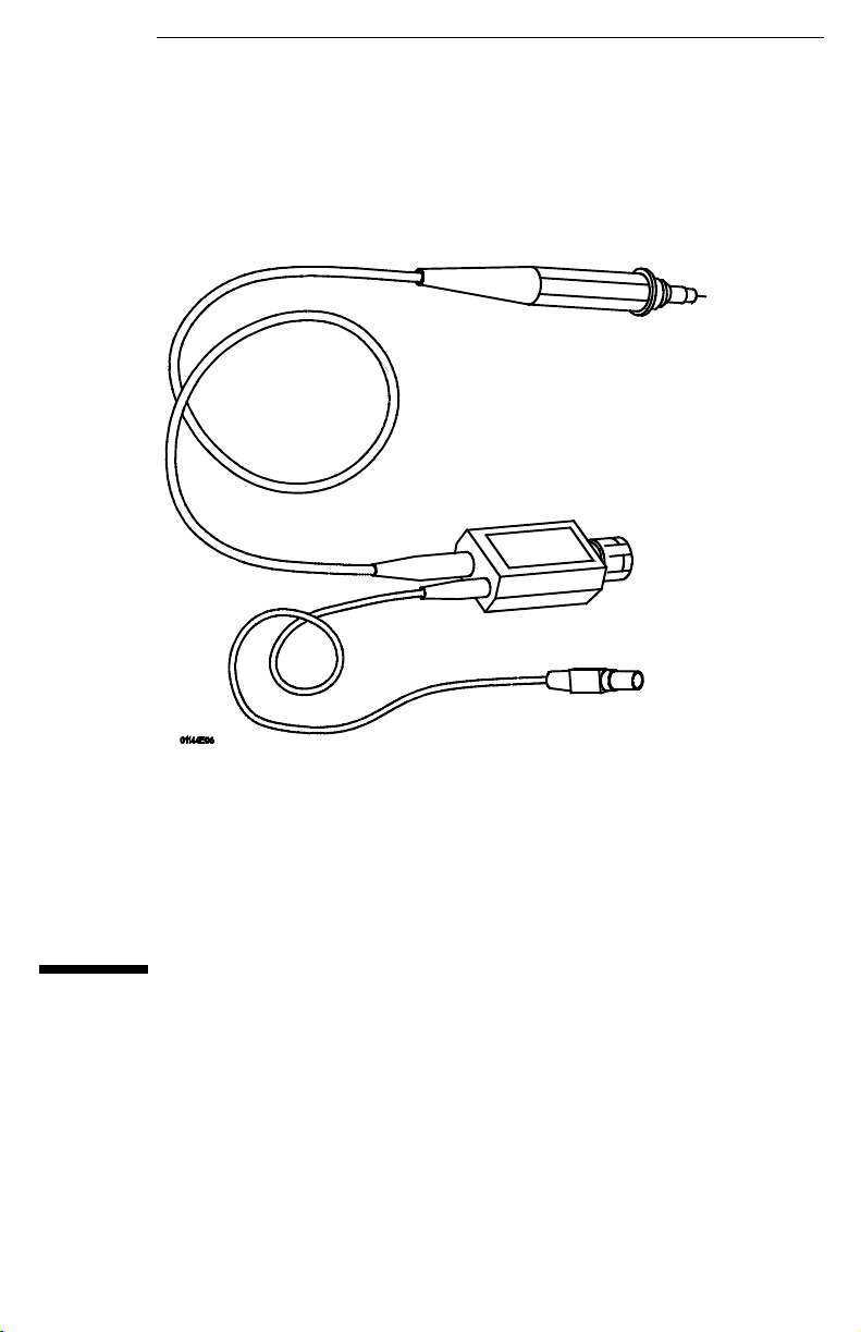
1144A Active Probe
The 1144A Active Probe is a 10:1 probe with an 800 MHz bandwidth. An FET at
the input allows a high input resistance and low input capacitance which
minimizes the loading of the circuit under test. The output impedance of the
probe is 50 Ω which allows the probe cable to be extended with a 50 Ω coaxial
cable. The probe can be powered by the probe power outputs of the 54520A,
54522A, 54540A, or 54542A oscilloscopes. To use the probe with other
instruments you can use the 1142A power supply.
Accessories Supplied
The following accessories are supplied with the 1144A probe.
1
2
3
4
5
1 Retractable pincher tip 6 Ground lead
2 Alligator clip ground lead 7 Dual lead adapter
3 BNC adapter 8 Mini-pincher tip
4 IC tip 9 Mini-pincher tip
5 Ground bayonet
6
7
8
9
(black)
(red)
You can order a kit of accessory parts from Agilent Technologies, part number
01144-68702.
3
Page 4

1144A Active Probe
Specifications
Accessories Available
The following accessories are available and can be ordered separately.
• Fan-out adapter, Agilent Technologies part number 01144-61604, to operate
two probes from one supply connector.
Specifications
The following specifications apply to the 1144A.
1
Bandwidth
Rise Time
Attenuation
≥800 MHz
1,2
≤440 ps
3
10:1 ±2%
Input Resistance 1 MΩ, ±5%
Maximum Input Voltage ±40 V (dc + peak ac)
1. Above 35 °C, bandwidth and risetime degrade approximately 1/2%/°C
2. Rise time figure calculated from tr = 0.35/Bandwidth.
3. When connected to an instrument input of 50 Ω, ±0.5%
Characteristics
The following are characteristics of the 1144A.
Input Capacitance 2 pF (typical)
Overshoot and Ringing 1 ±10% for the first 6 ns, ±4% from 6 ns to 20 ms,
±1.5% thereafter
Output Voltage Offset <±15 mV
2
Input Dynamic Range
0 to ±7.0 V
Output Load Requirement 50 Ω ±0.5%
1. When used with a 3 GHz oscilloscope (oscilloscope characteristics excluded).
2. When connected to an instrument input of 50 Ω, ±0.5%
4
Page 5

General Characteristics
The 1144A Active Probe has the following general characteristics.
Environmental
Conditions
Temperature 0 C to +55 °C (32 °F to
Humidity up to 95% relative humidity
Altitude up to 4,600 meters
Vibration Random vibration 5 to 500
Power
Requirements
!
Weight Net: approximately 180 g (~6.5 oz), probe body 35 g (~1.25
Dimensions Refer to the outline drawing below.
Operating Non-operating
-40 °C to +70 °C (-40 °F to
+131 °F)
(non- condensi ng) at +40 °C
(+104 °F)
(15,000 ft)
Hz, 10 minutes per axis,
.
0.3g
rms
dc ±12 V to ±15 V ±5% (at approximately 75 mA each
supply)
oz) Shipping: approximately 0.8 kg (1.75 lb)
+158 °F)
up to 90% relative humidity
at +65°C (+149 °F)
up to 15,300 meters
(50,000 ft)
Random vibration 5 to 500
Hz, 10 min. per axis,
2.41 g
5 to 500 Hz swept sine,
1octave/min. sweep rate,
(0.75g), 5 min. resonant
dwell at 4 resonances per
axis.
. Resonant search
rms
1144A Active Probe
General Characteristics
1144A Dimensions.
.
5
Page 6

1144A Active Probe
Operating the Probe
Operating the Probe
The following information will help you get the most out of your measurement
when operating the probe.
Operating Voltage Derating
6
Page 7
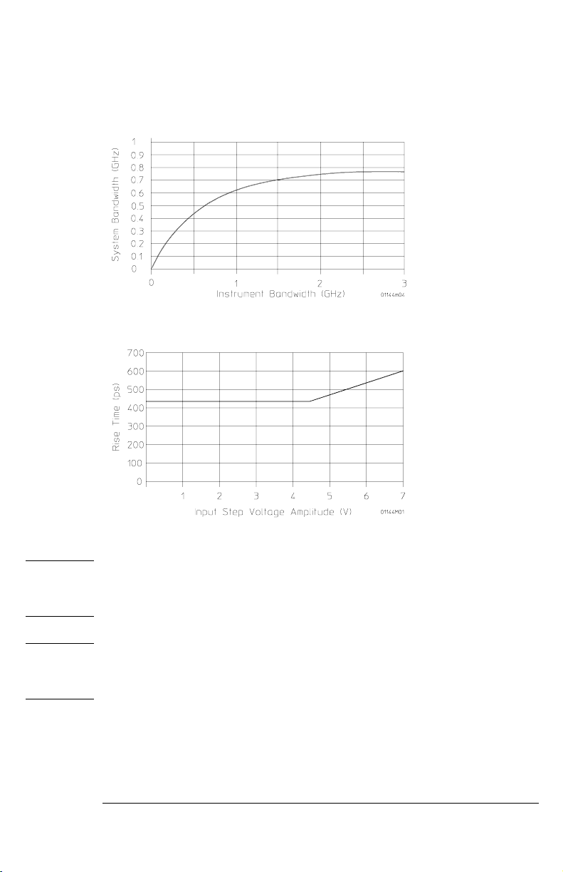
Typical Input Impedance vs. Frequency
System Bandwidth
1144A Active Probe
Operating the Probe
Typical Risetime vs. Input Voltage
CAUTION Be sure to limit the input of this probe to voltages within the specified working
voltage. Though the probe is designed with safeguards against static electricity
and noise, the input is sensitive to and may be damaged by excessive voltage.
CAUTION This probe is a sophisticated and delicate device. Please handle it with care.
Dropping it or exposing it to strong vibration or shock can damage it and cause
a malfunction.
7
Page 8

1144A Active Probe
Probe Power Connection
Probe Power Connection
The following drawing shows the input power connections. The power
requirements are given in the General Characteristics.
Pin 4, -15 V
Pin 6, +15 V
Pin 7, Ground
Shell, Cable Sheild
Cleaning the Probe
Do not use petroleum based solvents to clean the probe. Clean the probe with
a neutral detergent in water and immediately wipe the probe with a dry cloth.
Service Strategy
Other than the accessories, there are no replaceable parts on the 1144A Active
Probe. If your probe fails during warranty, normal warranty services apply. If the
probe is not under warranty when it fails, it can be exchanged for a reconditioned
probe at a nominal cost. The reconditioned probe is Agilent Technologies part
number 01144-69701. Contact your Agilent Technologies representative for
further information.
8
Page 9

1144A Active Probe
To return the probe for service
To return the probe for service
Before shipping the instrument to Agilent Technologies, contact your nearest
Agilent Technologies sales office for additional details.
1
Write the following information on a tag and attach it to the instrument.
• Name and address of owner
• Instrument model number
• Description of the service required or failure indications
2
Remove all accessories from the instrument.
Accessories include all cables. Do not include accessories unless they are
associated with the failure symptoms.
3
Protect the instrument by wrapping it in plastic or heavy paper. Antistatic wrapping or packaging is strongly recommended.
4 Pack the instrument in foam or other shock absorbing material and
place it in a strong shipping container.
You can use the original shipping materials or order materials from an Agilent
Technologies Sales Office. If neither are available, place 3 to 4 inches of shockabsorbing material around the instrument and place it in a box that does not
allow movement during shipping.
Seal the shipping container securely.
5
6 Mark the shipping container as FRAGILE.
In any correspondence, refer to instrument by model number and full serial
number.
Calibration Testing Procedures
These procedures are used to test the warranted specifications for the 1144A
Active probe. Use the equipment listed in the “Test Equipment Required” section
to complete the Testing Procedures.
Testing Interval
The calibration test procedures may be performed for incoming inspection of the
instrument and should be performed periodically thereafter to ensure and
maintain peak performance. The recommended test interval is yearly or every
2,000 hours of operation. Amount of use, environmental conditions, and the
user’s experience concerning need for testing will contribute to verification
requirements.
9
Page 10

1144A Active Probe
Calibration Testing Procedures
Equipment Required
The equipment required for the calibration tests is listed at the test. Any
equipment satisfying the critical specifications listed may be substituted for the
recommended model.
CAUTION Allow the probe to warm up for at least 15 minutes prior to beginning calibration
Input
Resistance
tests. Failure to allow warm-up may cause the probe to fail tests.
This test checks the input resistance of the active probe.
Specification 1.0 MΩ ±5%
Equipment Required
Equipment Critical Specification Recommended
Digital Multimeter Resistance ±1% 34401A
1
Connect the DMM between the probe tip and the ground shell at the
Model/Part
front of the probe.
2 Set up the DMM to measure resistance.
The resistance should read 1.0 MΩ ±50 kΩ.
Gain
Accuracy
This test checks the gain accuracy of the probe
Specification 0.1 ±2% (into 50 Ω ±0.5%)
Equipment Required
Equipment Critical Specification Recommended
Model/Part
Signal Generator 1 kHz and 1 Vrms 3312A
Digital Multimeter Better than 0.1% accuracy at 1 kHz 34401A
Power Supply Power for probe under test Oscilloscope or
1142A
Blocking cap 0.18 mF (or 0.1 mF fixed capacitor) 10240B
Adapter BNC(f)-to-probe (suppl’d with probe) 5081-7705
Adapter N(f)-to-BNC(m) 1250-0077
Termination BNC feed-through, 50 Ω ±0.5% 10100C (test to 0.5%)
Adapter BNC (f) to banana (m) 1251-2277
10
Page 11

1
Connect the power connector of the active probe to the oscilloscope or
1142A.
2 Connect the 50 Ω feedthrough to the output of the probe.
If your termination is not accurate to 0.5%, you will need to adjust your test
results accordingly, about 0.05% for each 0.1% error in the load.
3
AC couple the voltmeter by connect the blocking capacitor in series
with the voltmeter input.
This is to insure that there is no dc component in the signal measurement.
4
Set the signal generator for 1 kHz and 1.000 Vrms ±0.5% (±5.0mV). Use
the DVM to measure the signal.
Generator voltage __________
5
Using the BNC-to-probe adapter, connect the probe input to the output
of the signal generator.
6 Use the voltmeter to measure the signal at the output of the probe.
Connect the feedthrough termination to the blocking capacitor.
Probe output voltage ___________
7
Calculate the ac gain.
ac Gain
The ac gain should be between 0.098 and 0.102 (0.10 ±2.0%).
Bandwidth This test checks the probe bandwidth.
Specification down less than 3 dB, dc to 800 MHz
Probe output voltage
------------- ------------- ------------ ------------=
Generator voltage
1144A Active Probe
Calibration Testing Procedures
Equipment Required
Equipment Critical Specification Recommended
Signal Generator 50 MHz to 800 MHz 8663A
Power Meters (2)
or one DualChannel
Power Sensor (2) 50 MHz to 800 MHz, 300 mW 8482A
Power Splitter Type-N, dc to 800 MHz, ≤0.2 dB tracking 11667A
Power Supply Power for probe under test Oscilloscope or
Adapter (2) Type N(m) to BNC(f), 50 Ω 1250-0780
Termination BNC feedthrough, 50 Ω 10100C
Adapter BNC(f)-to-probe (suppl’d with probe) 5081-7705
50 MHz to 800 MHz, ±3% accuracy 436A (2),
Model/Part
437A (2), or
438A (1)
1142A
11
Page 12

1144A Active Probe
Calibration Testing Procedures
Equipment Critical Specification Recommended
Adapter N(f-f), 50 Ω 1250-0772
Adapter N(m-m), 50 Ω 1250-0778
1
Zero and calibrate the power meters with the power sensors.
2 Connect the equipment as in the drawing below.
Model/Part
3 Connect the probe power input to the oscilloscope or 1142A.
4 Set the signal generator for 50 MHz at 0.0 dBm.
5 Set the power meter calibration factors to the 50 MHz value on the
power sensors.
6 Adjust the signal generator power output for exactly -6.0 dBm as read
on the input power meter.
7 Note the power level reading on the output power meter. 50 MHz power
level _______________ dBm.
The output power level will be approximately -26 dBm. This corresponds to the
10:1 division ratio of the probe.
12
Page 13

1144A Active Probe
Calibration Testing Procedures
8
Change the signal generator frequency to 800 MHz.
9 Set the power meter calibration factors to the 800 MHz value on the
power sensors.
10 Re-level the signal generator output power for a -6.0 dBm reading on
the input power meter.
11 Note the power level reading on the output power meter. 800 MHz
power level _______________ dBm
12 Subtract the reading in step 7 from the reading in step 11.
The difference should be ≤3.0 dB
13
Page 14

1144A Active Probe
Calibration Test Record
Calibration Test Record
Agilent Technologies
Recommended Test Interval: 1 Year
Recommended Date of Next Certification:_________
Certification Temperature:_____________________
1144A 800 MHz Differential Probe
Serial No.:_______________________
Certification Date:_________________
Tested By:_______________________
_______________________________
_______________________________
Test Limits Results
Input Resistance 1.0 MΩ ±5%
Gain Accuracy 0.1 ±2% (into 50 Ω ±5%)
Bandwidth Down less than 3dB, dc to 800 MHz
14
Page 15

DECLARATION OF CONFORMITY
According to ISO/IEC Guide 22 and CEN/CENELEC EN 45014
Manufacturer's Name: Agilent Technologies, Inc.
Manufacturer's Address: 1900 Garden of the Gods Road
Declares, that the product
Product Name: Active Probe
Model Number(s): 1144A
Product Option(s): This declaration covers all options of the above product(s).
Conforms with the following product standards:
EMC: Standard
IEC 61326-1:1997+A1:1998 / EN 61326-1:1997+A1:1998
CISPR 11:1990 / EN 55011:1991
IEC 61000-4-2:1995+A1:1998 /EN 61000-4-2:1995
IEC 61000-4-3:1995 / EN 61000-4-3:1995
IEC 61000-4-4:1995 / EN 61000-4-4:1995
IEC 61000-4-5:1995 / EN 61000-4-5:1995
IEC 61000-4-6:1996 / EN 61000-4-6:1996
IEC 61000-4-11:1994 / EN 61000-4-11:1994
Canada: ICES-001:1998
Australia/New Zealand: AS/NZS 2064.1
Safety: IEC 61010-1:1990+A1:1992+A2:1995 / EN 61010-1:1993+A2:1995
Canada: CSA C22.2 No. 1010.1:1992
Supplementary Information:
Colorado Springs, CO
80907, U.S.A.
Limit
Group 1 Class A
4kV CD, 8kV AD
3 V/m, 80-1000 MHz
0.5kV signal lines, 1kV power lines
0.5 kV line-line, 1 kV line-ground
3V, 0.15-80 MHz
1 cycle, 100%
[1]
The product herewith complies with the requirements of the Low Voltage Directive 73/23/EEC
and the EMC Directive 89/336/EEC (including 93/68/EEC, and carries the CE-marking accordingly
(European Union).
[1]
This product was tested in a typical configuration with Agilent Technologies test systems.
Date: 08/21/2000
Ken Wyatt / Product Regulations Manager
For further information, please contact your local Agilent Technologies sales office, agent or distributor.
Page 16

Product Regulations
Performance
Criteria
EMC IEC 61326-1:1997+A1:1998 / EN 61326-1:1997+A1:1998
CISPR 11:1990 / EN 55011:1991
IEC 61000-4-2:1995+A1:1998 /EN 61000-4-2:1995
IEC 61000-4-3:1995 / EN 61000-4-3:1995
IEC 61000-4-4:1995 / EN 61000-4-4:1995
IEC 61000-4-5:1995 / EN 61000-4-5:1995
IEC 61000-4-6:1996 / EN 61000-4-6:1996
IEC 61000-4-11:1994 / EN 61000-4-11:1994
A
B
A
A
A
A
Canada: ICES-001:1998
Safety IEC 61010-1:1990+A1:1992+A2:1995 / EN 61010-1:1993+A2:1995
Canada: CSA C22.2 No. 1010.1:1992
Addtional Information
The product herewtih complies with the requirements of the Low Voltage Directive 73/23/EEC
and the EMC Directive 89/336/EEC (including 93/68/EEC) and carries the CE Marking
accordingly (European Union).
1
Performance Codes:
A PASS - Normal operation, no effect.
B PASS - Temporary degradation, self recoverable.
C PASS - Temporary degradation, operator intervention required.
D FAIL - Not recoverable, component damage.
Notes:
Sound Pressure Level N/A
Regulatory Information for Canada
ICES/NMB-001
This ISM device complies with Canadian ICES-001.
Cet appareil ISM est confomre à la norme NMB-001 du Canada.
Regulatory Information for Australia/New Zealand
This ISM device complies with Australian/New Zealand AS/NZS 2064.1
Page 17

Safety
Notices
This apparatus has been
designed and tested in accordance with IEC Publication
1010, Safety Requirements for
Measuring Apparatus, and
has been supplied in a safe
condition. This is a Safety
Class I instrument (provided
with terminal for protective
earthing). Before applying
power, verify that the correct
safety precautions are taken
(see the following warnings).
In addition, note the external
markings on the instrument
that are described under
"Safety Symbols."
Warnings
• Before turning on the instrument, you must connect the
protective earth terminal of
the instrument to the protective conductor of the (mains)
power cord. The mains plug
shall only be inserted in a
socket outlet provided with a
protective earth contact. You
must not negate the protective action by using an extension cord (power cable)
without a protective conductor (grounding). Grounding
one conductor of a two-conductor outlet is not sufficient
protection.
• Only fuses with the required
rated current, voltage, and
specified type (normal blow,
time delay, etc.) should be
used. Do not use repaired
fuses or short-circuited fuseholders. To do so could cause
a shock or fire hazard.
• If you energize this instrument by an auto transformer
(for voltage reduction or
mains isolation), the common
terminal must be connected to
the earth terminal of the
power source.
• Whenever it is likely that the
ground protection is impaired,
you must make the instrument
inoperative and secure it
against any unintended operation.
• Service instructions are for
trained service personnel. To
avoid dangerous electric
shock, do not perform any service unless qualified to do so.
Do not attempt internal service or adjustment unless
another person, capable of
rendering first aid and resuscitation, is present.
• Do not install substitute parts
or perform any unauthorized
modification to the instrument.
• Capacitors inside the instrument may retain a charge
even if the instrument is disconnected from its source of
supply.
• Do not operate the instrument in the presence of flammable gasses or fumes.
Operation of any electrical
instrument in such an environment constitutes a definite
safety hazard.
• Do not use the instrument in
a manner not specified by the
manufacturer.
To clean the instrument
If the instrument requires
cleaning: (1) Remove power
from the instrument. (2) Clean
the external surfaces of the
instrument with a soft cloth
dampened with a mixture of
mild detergent and water. (3)
Make sure that the instrument is completely dry before
reconnecting it to a power
source.
Safety Symbols
!
Instruction manual symbol:
the product is marked with
this symbol when it is necessary for you to refer to the
instruction manual in order to
protect against damage to the
product..
Hazardous voltage symbol.
Earth terminal symbol: Used to
indicate a circuit common
connected to grounded chassis.
Agilent Technologies
P.O. Box 2197
1900 Garden of the Gods Road
Colorado Springs, CO 80901
Page 18

Notices
© Agilent Technologies, Inc.
2002
No part of this manual may be
reproduced in any form or by
any means (including electronic storage and retrieval or
translation into a foreign language) without prior agreement and written consent
from Agilent Technologies,
Inc. as governed by United
States and international copyright laws.
Manual Part Number
01144-97001, September 2002
Print History
01144-90901, June 1993
01144-97000, July 2000
01144-97001, July 2002
Agilent Technologies, Inc.
1900 Garden of the Gods Road
Colorado Springs, CO 80907
USA
Restricted Rights Legend
If software is for use in the
performance of a U.S. Government prime contract or subcontract, Software is
delivered and licensed as
“Commercial computer software” as defined in DFAR
252.227-7014 (June 1995), or as
a “commercial item” as
defined in FAR 2.101(a) or as
“Restricted computer software” as defined in FAR
52.227-19 (June 1987) or any
equivalent agency regulation
or contract clause. Use, duplication or disclosure of Software is subject to Agilent
Technologies’ standard commercial license terms, and
non-DOD Departments and
Agencies of the U.S. Government will receive no greater
than Restricted Rights as
defined in FAR 52.227-19(c)(1-
2) (June 1987). U.S. Government users will receive no
greater than Limited Rights as
defined in FAR 52.227-14 (June
1987) or DFAR 252.227-7015
(b)(2) (November 1995), as
applicable in any technical
data.
ual and any information
contained herein, including but not limited to the
implied warranties of
merchantability and fitness for a particular purpose. Agilent shall not be
liable for errors or for
incidental or consequential damages in connection with the furnishing,
use, or performance of
this document or of any
information contained
herein. Should Agilent
and the user have a separate written agreement
with warranty terms covering the material in this
document that conflict
with these terms, the warranty terms in the separate agreement shall
control.
Technology Licenses
The hardware and/or software described in this document are furnished under a
license and may be used or
copied only in accordance
with the terms of such license.
WARNING
A WARNING notice
denotes a hazard. It
calls attention to an
operating procedure,
practice, or the like
that, if not correctly
performed or adhered
to, could result in
personal injury or
death. Do not proceed
beyond a WARNING
notice until the
indicated conditions
are fully understood
and met.
CAUTION
A CAUTION notice
denotes a hazard. It
calls attention to an
operating procedure,
practice, or the like
that, if not correctly
performed or adhered
to, could result in
damage to the product
or loss of important
data. Do not proceed
beyond a CAUTION
notice until the
indicated conditions
are fully understood
and met.
Document Warranty
The material contained in
this document is provided
“as is,” and is subject to
being changed, without
notice, in future editions.
Further, to the maximum
extent permitted by applicable law, Agilent disclaims all warranties,
either express or implied,
with regard to this man-
Page 19

Page 20

sA
Agilent Technologies
Printed in Malaysia
Part Number
01144-97001
*01144-97001*
User’s Guide
 Loading...