

Page 1
User’s Guide
Publication number 10433-92001
November 1999
s1
For Safety information, Warranties, Regulatory information, and publishing information,
see the pages at the back of this book.
© Copyright Agilent Technologies Company 1998-1999
All Rights Reserved.
Agilent 10400B Series Miniature
Passive Oscilloscope Probes
Page 2

Contents
Inspect the probe 2
Probe parts supplied 4
!
Probe characteristics 8
Bandwidth considerations 10
Safety considerations 11
Cleaning the probe 11
To connect oscilloscope probes 12
To operate the probe 13
Compensation adjustments 16
Inspect the probe
❏ Inspect the shipping container for damage.
Keep a damaged shipping container or cushioning material until the contents of
the shipment have been checked for completeness and the probe has been
checked mechanically and electrically.
❏ Check the accessories.
Any accessories that were supplied with the probe are listed in "Available
accessories" in this manual.
• If the contents are incomplete or damaged, notify your Agilent Technologies
Sales Office.
❏ Inspect the instrument.
• If there is mechanical damage or defect, or if the probe does not operate
properly or pass performance tests, notify your Agilent Technologies Sales
Office.
• If the shipping container is damaged, or the cushioning materials show signs
of stress, notify the carrier as well as your Agilent Technologies Sales Office.
Keep the shipping materials for the carrier’s inspection. The Agilent
Technologies office will arrange for repair or replacement at Agilent
Technologies’ option without waiting for claim settlement.
2
Page 3

Agilent 10400B Series Miniature Passive
Oscilloscope Probes
The Agilent 10400B Series Miniature Passive Oscilloscope Probes provide
improved usability and performance of the Agilent 10400A Series Probes, and
they offer a broader range of accessories. The Agilent 10400B Series Probes
replace the Agilent 10400A Series, but maintain compatibility with them. To
select the appropriate replacement probe, see the following table.
Agilent 10400A Family Agilent 10400B Family
10430A, 10431A, 10441A 10441B
10432A, 10433A, 10435A 10433B
10434A, 10436A 10436B
10437A 10437B
10438A, 10439A 10439B
10440A 10440B
10442A 10442B
10444A 10073B
The Agilent Technologies B Series of miniature probes significantly reduces the
problem of probing densely populated integrated circuit components and
characteristically small conductors on printed circuit boards. These small, lightweight probes allow measurements that were previously very difficult, while
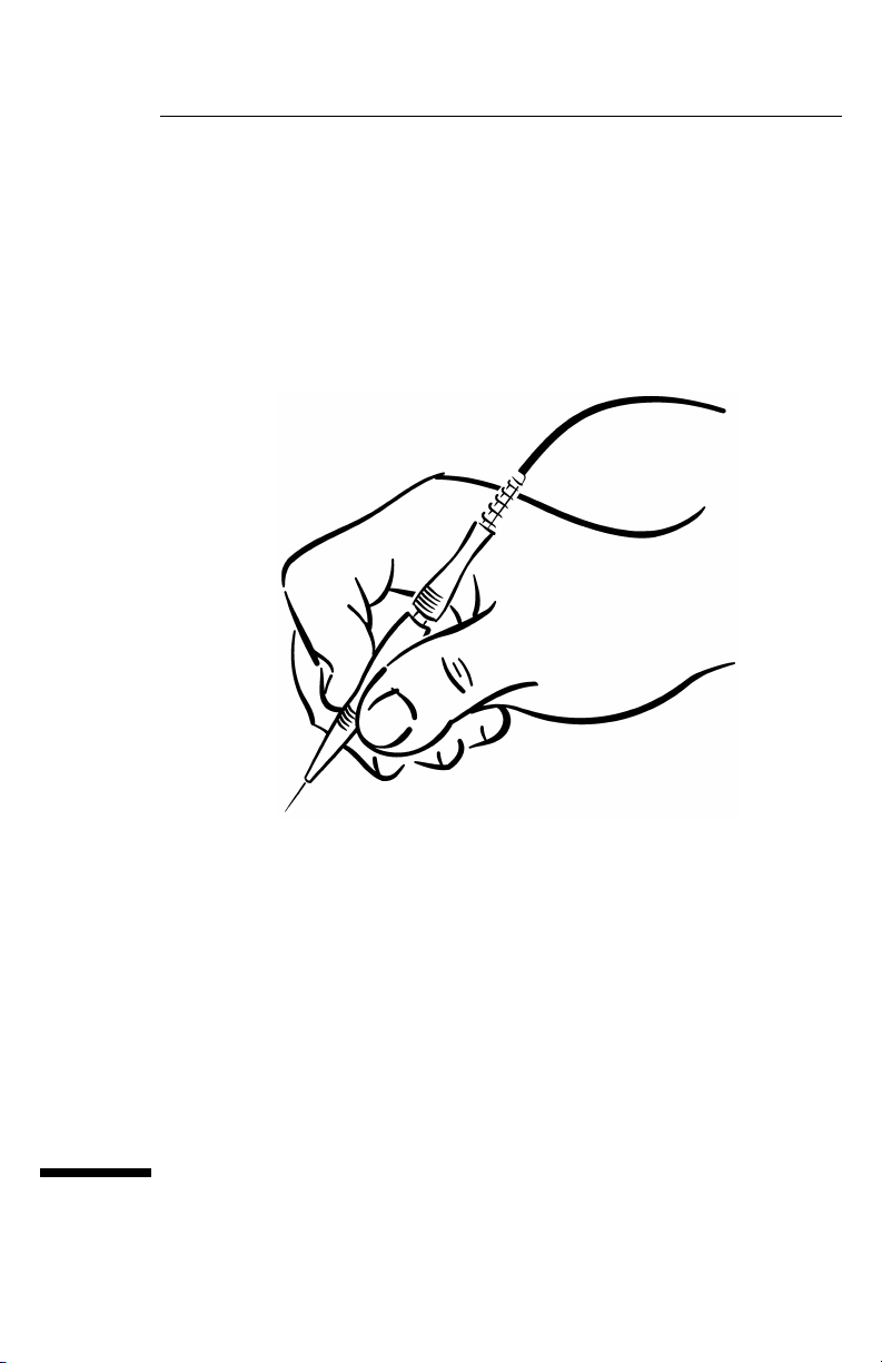
reducing the hazard of shorting. The probe body fits in the hand as comfortably
as a pencil.
Each probe includes a browser tip that will not slip off of the test point being
probed and short to some adjacent point. The browser uses a crown point that
“digs in” to solder, and will not slip.
These probes include a variety of ground leads for attaching to many different
ground points. Probe packaging provides convenient storage and ordering
information for replacement parts.
Other key features
• Narrow, sharp, replaceable probe tip.
• Browser attachment with ultra-sharp crown point. Use this to probe the
circui t in de bug mode. The crow n point will not easi ly slip off of the lead you
are probing. The pogo pin allows hand movement without losing contact.
• An assortment of long and short ground leads for connecting to a wide variety
of points.
• Handle unscrews and pulls back to reduce the size of the probe.
• General-purpose retractable hook tip made of strong, durable music wire.
• Flexible, light-weight cable with kevlar strengthener.
• Multi-position barrel insulator exposes as much or as little probe ground as
desired at the probe tip.
• P robe comes in a con veni e nt sto rage box, wi th lab eled infor matio n on how to
reorder parts.
• Automatic Probe Identification Pin (Agilent 10441B only).
3
Page 4
Agilent 10400B Series Miniature Passive Oscilloscope Probes
Probe parts supplied
Probe parts supplied
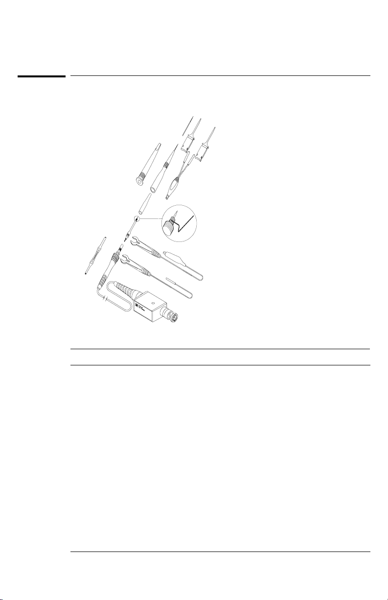
Parts supplied with the Agilent 10400B Series Probes are shown below.
12
7
4
5
6
3
2
11
Parts of the Agilent 10400B Series Probes
8
9
10
1
label.cdr
Agilent 10400B Series Probe Parts
Item Description Quantity
1Probe 1
2Probe tip 2
3 Barrel insulator 2
4Browser 1
5 General-purpose retractable hook tip 1
6 Dual-lead adapter 1
7SMD clip 2
8 Spring ground 4
9 Alligator ground lead 1
10 Socketed ground lead 1
11 Screwdriver 1
12 Browser pogo pin (spare) 1
You can order additional quantities of these parts. See the ordering information in this manual.
4
Page 5

Agilent 10400B Series Miniature Passive Oscilloscope Probes
Probe parts supplied
To order replaceable parts
To order a replaceable part, in the United States call our toll-free hotline at
1-877-447-7278, or call your local Agilent Technologies Sales Office.
The following table shows replacement parts that you can order directly from
Agilent Technologies.
Replacement Parts for Agilent 10400B Series Probes
Item Replacement Part Agilent Part Number
1 10400B Series Probe
(For replacement, order the entire probe assembly.)
2 10433B probe tip (quantity 5) — Blue 5063-2167
2 10436B probe tip (quantity 5) — Green 5063-2168
2 10437B probe tip (quantity 5) — Black 5063-2138
2 10439B probe tip (quantity 5) — Black 5063-2138
2 10440B probe tip (quantity 5) — Yellow 5063-2171
2 10441B probe tip (quantity 5) — Violet 5063-2172
2 10442B probe tip (quantity 5) — Grey 5063-2139
3 Barrel insulator (quantity 4) See * below
4 Browser (quantity 1) 5063-2115
5 General-purpose retractable hook tip (quantity 2) 5063-2135
6 Dual-lead adapter (quantity 1) 5063-2147; See ** below
7 SMD clip (quantity 5) 5063-2149
8 Spring ground (quantity 4) See * below
9 Alligator ground lead (quantity 2) 5063-2140
10 Socketed ground lead (quantity 1) 5063-2120
11 Screwdriver See * below
12 Browser pogo pin (quantity 4) See * below
Accessory kit * 01160-68701
* Accessory kit includes 4 spring grounds, 4 browser pogo pins, 4 barrel insulators, and
1 screwdriver.
** Provides interface with the Agilent Wedges.
Models: 10433B, 10436B,
10437B, 10439B, 10440B,
10441B, or 10442B.
5
Page 6
Agilent 10400B Series Miniature Passive Oscilloscope Probes
Probe parts supplied
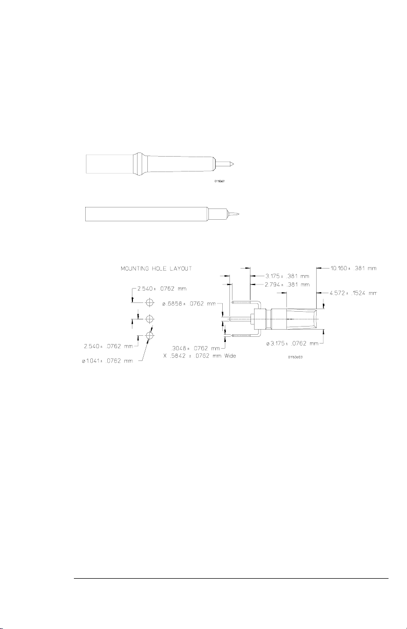
Available accessories
• Agilent 10467-68701 SMD microclips for connection to SMT parts with lead
spacings of 0.5 mm (0.020 inch) to 0.8 mm (0.032 inch).
• Agilent 5063-2143 probe tip-to-BNC adapter.
• Agilent 10100C BNC(m)-to-BNC(f) 50Ω feedthrough terminator.
• Agilent N2844A flexible tip jack adapter
• Agilent E9639A 5 mm socket adapter.
• Agilent N2767A (Qty 5) or Agilent N2768A (Qty 25) vertical mini-probe
socket.
6
Page 7
Agilent 10400B Series Miniature Passive Oscilloscope Probes
Probe parts supplied
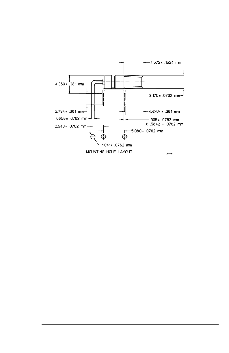
• Agilent N2765A (Qty 5) or Agilent N2766A (Qty 25) horizontal mini-probe
socket.
7
Page 8
Agilent 10400B Series Miniature Passive Oscilloscope Probes
z
z
Probe characteristics
Probe characteristics
Agilent 10400B Series Probes Operating Characteristics
Approximate Lengths of Probe Propagation Delay
Approximate probe length = 1 meter 4.5 ns
Approximate probe length = 1.5 meters 6.7 ns
Approximate probe length = 2 meters 9 ns
Safety Meets IEC1010-2-31
Pull strength (BNC to probe tip) ≤12 lb static pull
Pollution degree 2 Normally only non-conductive pollution
occurs. Oc casionally, however, a te mporary
conductivity caused by condensation must be
expected.
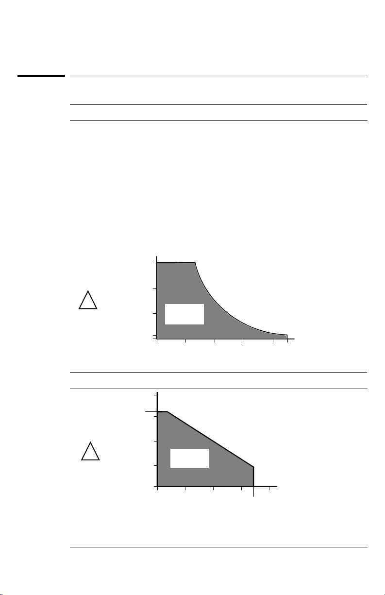
Voltage versus Frequency Rating Curve (except Agilent 10439B)
300
30 MHz
Excessive power
dissi pation
area
100 MHz
Max
Voltage
Input
!
(peak ac)
CAT II
200
Acceptable
100
probe operat ion
area
5
3MHz
10 MHz
Frequency
Voltage versus Frequency Rating Curve (Agilent 10439B)
625 V
150 V
125 V
1MHz
Frequency
Excessive power
dissi pation
area
10 MHz
Max
25 V
Vol t a g e
Input
!
(peak ac)
CAT II
5V
1V
10 KHz
Acceptable
probe operat ion
area
100 KHz
HP 10439B1:1Probe
8
43 MHz
300 MHz
100 MH
500 MH
Page 9
Agilent 10400B Series Miniature Passive Oscilloscope Probes
Probe characteristics
The above curve only applies to 10 MΩ, 10:1 probes with the oscilloscope’s input
impedance set to 1 MΩ.
The Agilent 10437B 50Ω probe is rated at 5 V
The Agilent 10442B 500Ω p r ob e i s r a t ed a t 1 0 V
I).
maximum (CAT I).
RMS
( dc + a c
RMS
RMS
) maximum (CAT
Environmental Characteristics
Temperature
0 °C to +55 °C
(operating)
Humidity (operating) Up to 95% relative humidity at 40 °C
Altitude (operating) Up to 4,600 meters (15,000 ft)
Shock 50 g (400 g tip only)
Weight 2.6 oz.
Indoor Use
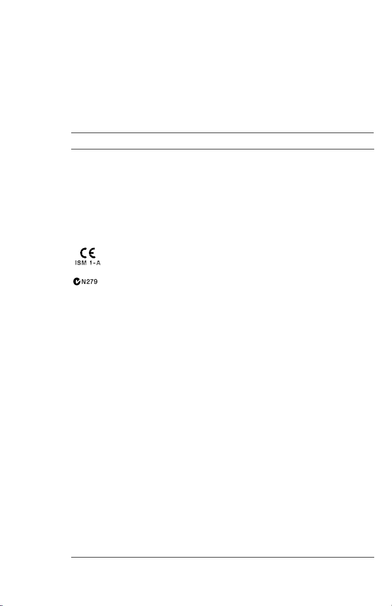
This symbol indicates that the Agilent 10400B Series Probes are in
compliance with European product regulations, including the
EMC Directive and the Low Voltage Directive.
This symbol indicates that the Agilent 10400B Series Probes are in
compliance with Australian product regulations.
CAT I and CAT II Definitions
Installation category (overvoltage category) I: Signal level, special equipment
or parts of equipment, telecommunication, electronic etc., with smaller transient
overvoltages than installation category (overvoltage category) II.
Installation category (overvoltage category) II: Local level, appliances, portable
equipment etc., with smaller transient overvoltages than installation category
(overvoltage category) III.
9
Page 10

Agilent 10400B Series Miniature Passive Oscilloscope Probes
Bandwidth considerations
Bandwidth considerations
The dominant probe limitation to system bandwidth is its input capacitance,
assuming that the high-frequency compensation adjustments have been made.
The displayed bandwidth of any measurement system using an oscilloscope and
probe is determined by four factors: probe input capacitance, source impedance,
source bandwidth, and oscilloscope bandwidth.
Agilent 10400B Series Probes Selection Guide
Model
Number
10433B High-
10436B High-
10437B 50Ω Resistive
10439B High-
10440B High
10441B High-
10442B 500-Ω resistive
Type of Probe Bandwidth
impedance,
passive
impedance,
passive
Divider
impedance,
passive
impedance
passive
impedance,
passive
divider
The Agilent 10437B and Agilent 10442B probes are compatible with any
oscilloscope that has a 50 Ω input.
Scope/
Probe
System
300 MHz 10:1 10 MΩ 10 pF 1 MΩ 10-16 pF 2
300 MHz 10:1 10 MΩ 11 pF 1 MΩ 18-22 pF 2
1 GHz 1:1 50Ω n/a 50Ω n/a 2
n/a 1:1 1 MΩ n/a 1 MΩ n/a 1.5
300 MHz 100:1 10 MΩ 2.5 pF 1 MΩ 6-14 pF 2
500 MHz 10:1 1 MΩ 9 pF 1 MΩ 6-9 pF 1.8
1 GHz 10:1 500Ω n/a 50Ω n/a 1.5
Division
Ratio
Input R Input C Scope
Input R
Comp
Range
Length
(in
meters)
10
Page 11

Safety considerations
WARNING SHOCK HAZARD!
These probes are designed for use with oscilloscopes that have a common
terminal at GROUND POTENTIAL (in accordance with OSHA requirements and
the National Electric Code). Exposed metallic surfaces of the probe and the
oscilloscope MUST BE GROUNDED. Failure to ground the common terminal
during certain applications, such as those requiring the oscilloscope to be
powered from an external battery, might expose the operator to an electrical
shock hazard that could be lethal (depending on voltage and current
conditions.)
Cleaning the probe
If the Agilent 10400B Series Probe requires cleaning, disconnect it from all power
sources and clean it with a soft cloth dampened with a mild soap and water
so l u tio n . Ma k e s ure th e pro b e is c o mp let e l y dr y be fo re r e con n ec ti ng i t t o a pow e r
source.
Agilent 10400B Series Miniature Passive Oscilloscope Probes
Safety considerations
11
Page 12

Agilent 10400B Series Miniature Passive Oscilloscope Probes
To connect oscilloscope probes
To connect oscilloscope probes
1 Attach the probe connector to the desired oscilloscope channel.
2 Connect the probe to the circuit using any of the probing aids.
12
Page 13
Agilent 10400B Series Miniature Passive Oscilloscope Probes
To operate the probe
To operate the probe
When operating the Agilent 10400B Series Probes, these additional parts can
help:
• SMD Clip
The SMD clip lets you connect the Agilent 10400B Series Probe to SMT
parts with dual lead adapter. See “Available accessories” described earlier
for more information.
•BNC-to-Probe Tip Adapter
This tip adapter lets you attach the probe to a BNC cable.
• Spring Ground
The spring ground attaches to the probe to make ground contact with the
circuit board, while letting you angle and maneuver the probe around an
area.
CAUTION Do not solder probe tip to any surface. Solder will damage the probe tip.
CAUTION If you are using the probe without any accessories, the probe could cause a
short if you drop it within the circuit.
1 Attach the probe to the circuit.
You may use the probe tip pin without any accessories for probing in places that
are difficult to reach.
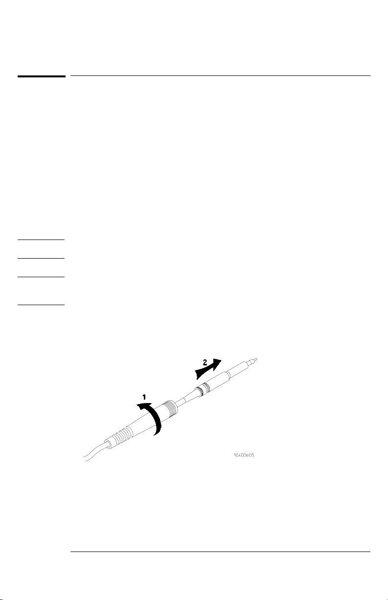
You may unscrew the cable strain relief from the probe and slide it back on the
cable when using two or more probes in cl ose proximity. When using the probe
without the browser or retractable hook tip, you should use the barrel insulator
(a supplied accessory) to cover the tip ground shield to prevent the hazard of
shorting when you are probing the circuit. You may unscrew the barrel insulator
and remove it to accommodate tight probing situations.
13
Page 14
Agilent 10400B Series Miniature Passive Oscilloscope Probes
To operate the probe
The barrel insulator can be screwed to multiple positions:
• With the barrel insulator screwed all the way on, you may add a spring ground
(a supplied accessory) to the probe tip to provide ground contact.
2
With the barrel insulator screwed most of the way out, the barrel
insulator covers the ground shield by the probe tip.
Ground the probe tip and barrel insulator.
Ground the probe by attaching either the alligator ground, socket ground, or
spring ground. Any of these ground accessories provides reference for a ground
point.
To avoid possible shorting of other circuitry, use the barrel insulator in
conjunction with any of the grounding accessories. For optimum performance,
use the shortest ground lead.
The browser.
3
The browser tip has a crown point that digs into solder and will not slip. The
spring-loaded pogo pin allows hand movement without losing contact.
4 The retractable hook tip.
Attach the hook tip to a probing point by pressing the retractable hook tip body
towards the probe body. Place the hook tip around the probing point, then
release the retractable hook tip body.
The retractable hook tip is used for most typical in-circuit probing and ICs.
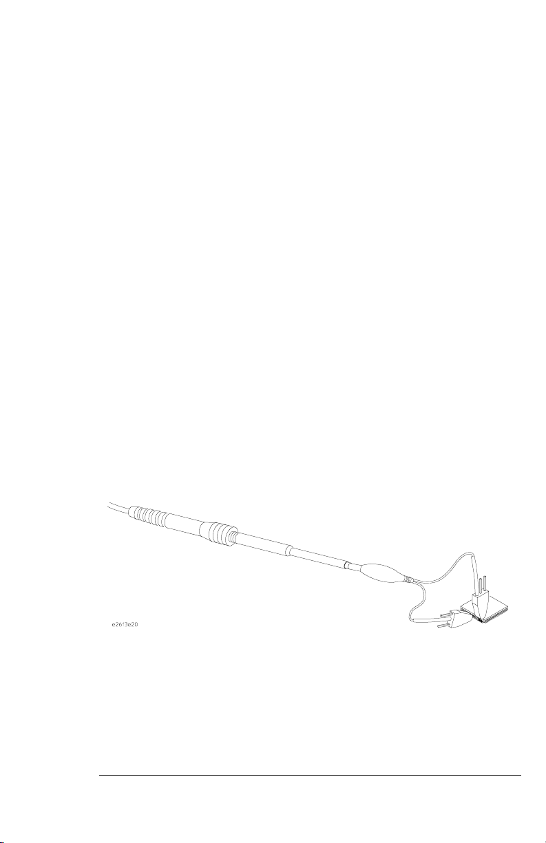
The Agilent Wedge Probe Adapter
The Agilent Wedge Probe Adapter makes contact with legs of the IC under test
when the Agilent Wedge Probe Adapter conductors are inserted into the space
between the legs of the IC. If you are using the Agilent Wedge Adapter, refer to
the supplied Agilent Wedge Adapter User’s Guide.
Connecting the Probe to an Agilent Wedge Adapter
14
Page 15

Agilent 10400B Series Miniature Passive Oscilloscope Probes
Agilent Wedge Adapters
Agilent Model Number Description
E2613A One 0.5 mm x 3-signal wedge
E2613B Two 0.5 mm x 3-signal wedge
E2614A One 0.5 mm x 8-signal wedge
E2615A One 0.65 mm x 3-signal wedge
E2615B Two 0.65 mm x 3-signal wedge
E2616A One 0.65 mm x 8-signal wedge
E2643A* One 0.5 mm x 16-signal wedge
E2644A* One 0.65 mm x 16-signal wedge
* 16-signal Agilent Wedge Probe Adapters include 3 removable jumpers
(Agilent part number 1258-0141 for quantity of 1 jumper)
To operate the probe
15
Page 16
Agilent 10400B Series Miniature Passive Oscilloscope Probes
Compensation adjustments
Compensation adjustments
You can adjust the probes for both low-frequency compensation and highfrequency compensation. Low-frequency compensation is an operating
adjustment. You should perform high-frequency compensation periodically
according to maintenance schedules.
When to Adjust Probe Compensation
Low-frequency compensation is adjusted when the probe is first connected
to the oscilloscope. Probe compensation will usually hold over all the
attenuator ranges when used with a Agilent Technologies oscilloscope. If
the input capacitance of the oscilloscope changes as ranges are switched,
compensation must be adjusted each time a new range is selected.
Adjusting low-frequency compensation
Before you can have a flat frequency response when using a compensated passive
divider probe, you must compensate the probe’s cable capacitance and scope
input capacitance to optimize the step response for flatness. You should
compensate your probe to match its characteristics to the oscilloscope. A poorly
compensated probe can introduce measurement errors.
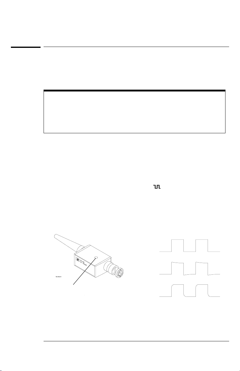
Connect the probe from the appropriate oscilloscope channel to the
1
front-panel probe adjust signal terminal [ ] on the scope.
You can attach the probe with the hole in the probe body facing up to allow
adjustment.
Press Autoscale.
2
3 Using the wide end of the supplied screwdriver tool, set the low-
frequency compensation adjustment on the probe for the flattest pulse
possible as shown below.
Perfectly Compensated
Low-frequency compensation
adjustment
Low-Frequency Adjustment and Waveforms
16
Over Compensated
Under Compensated
Page 17
Agilent 10400B Series Miniature Passive Oscilloscope Probes
Compensation adjustments
Adjusting high-frequency compensation
Do Low-Frequency Compensation First
You must do the low-frequency compensation procedure described previously
before doing this high-frequency compensation procedure.
To compensate for cable loss in your probe, you’ll need the equipment listed
below.
Equipment Required
Equipment Specification Agilent Part Number
50 Ω feedthrough 50 Ω BNC(m) and (f) 10100C
Adapter BNC-to-probe tip 5063-2143
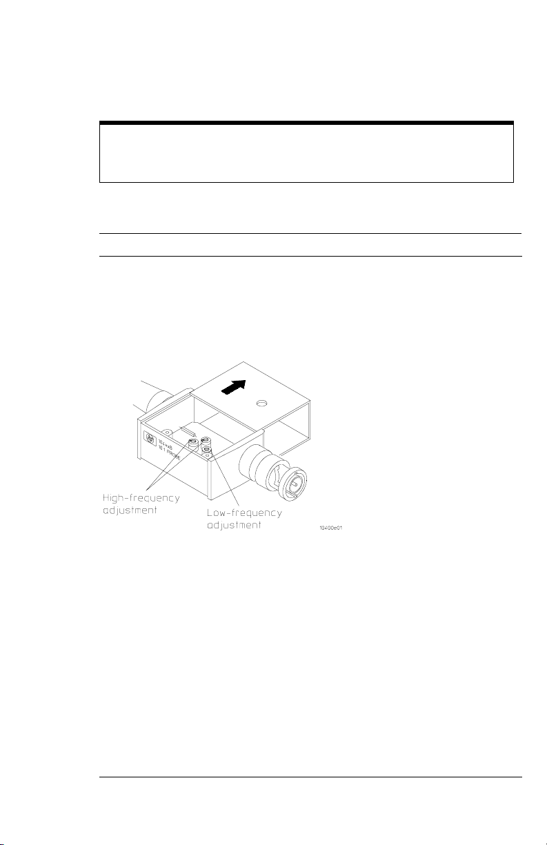
1 Remove the probe cover to provide access to the two high-frequency
compensation adjustment resistors.
High-Frequency Adjustments
2 Connect a 50 Ω feedthrough to the oscilloscope BNC ac cal out.
3 Connect the BNC-to-probe tip adapter to the 50 Ω feedthrough.
4 Remove any probing aid and the barrel insulator from the probe tip.
5 Connect the probe tip to the BNC-to-probe tip adapter.
6 Connect the probe BNC to the appropriate oscilloscope channel.
7 Press Autoscale, then set the time base to 5 ns/div.
8 Set the sample mode to equivalent time, and the # of averages to 4.
9 Rotate the two high-frequency compensation resistors fully clockwise.
10 Adjust the two high-frequency compensation resistors alternately in
small increments until the displayed waveform has the flattest top.
17
Page 18

18
Page 19

© Copyright
Agilent Technologies
Company 1998-1999.
All Rights Reserved.
Reproduction, adaptation,
or translation without prior
written permission is
prohibited, except as
allowed under the copyright
laws.
Restricted Rights
Legend.
Use, duplication or
disclosure by the U.S.
Government is subject to
restrictions as set forth in
subparagraph (c) (1) (ii) of
the Rights in Technical Data
and Computer Software
clause at DFARS 252.2277013 for DOD agencies, and
subparagraphs (c) (1) and
(c) (2) of the Commercial
Computer Software
Restricted Rights clause at
FAR 52.227-19 for other
agencies.
Agilent Technologies
Company
3000 Hanover Street
Palo Alto, California 94304
U.S.A.
Document Warranty
The information contained
in this document is subject
to change without notice.
Agilent Technologies
makes no warranty of
any kind with regard to
this material, including,
but not limited to, the
implied warranties of
merchantability or
fitness for a particular
purpose.
Agilent Technologies shall
not be liable for errors
contained herein or for
damages in connection with
the furnishing,
performance, or use of this
material.
Product Warranty
This Agilent Technologies
product has a warranty
against defects in material
and workmanship for a
period of one year from
date of shipment. During
the warranty period,
Agilent Technologies
Company will, at its option,
either repair or replace
products that prove to be
defective.
For warranty service or
repair, this product must be
returned to a service facility
designated by Agilent
Technologies.
For products returned to
Agilent Technologies for
warranty service, the Buyer
shall prepay shipping
charges to Agilent
Technologies and Agilent
Technologies shall pay
shipping charges to return
the product to the Buyer.
However, the Buyer shall
pay all shipping charges,
duties, and taxes for
products returned to
Agilent Technologies from
another country.
Agilent Technologies
warrants that its software
and firmware designated by
Agilent Technologies for
use with an instrument will
execute its programming
instructions when properly
installed on that
instrument. Agilent
Technologies does not
warrant that the operation
of the instrument software,
or firmware will be
uninterrupted or error free.
Limitation of Warranty
The foregoing warranty
shall not apply to defects
resulting from improper or
inadequate maintenance by
the Buyer, Buyer-supplied
software or interfacing,
unauthorized modification
or mi sus e, o pe rat ion ou tsi de
of the environmental
specifications for the
product, or improper site
preparation or
maintenance.
No other warranty is
expressed or implied.
Agilent Technologies
specifically disclaims the
implied warranties of
merchantability or
fitness for a particular
purpose.
Exclusive Remedies
The remedies provided
herein are the buyer's sole
and exclusive remedies.
Agilent Technologies shall
not be liable for any direct,
indirect, special, incidental,
or consequential damages,
whether based on contract,
tort, or any other legal
theory.
Assistance
Product maintenance
agreements and other
customer assistance
agreements are available for
Agilent Technologies
products.
For any assistance, contact
your nearest Agilent
Technologies Sales Office.
Certification
Agilent Technologies
Company certifies that this
product met its published
specifications at the time of
shipment from the factory.
Agilent Technologies
further certifies that its
calibration measu rements
are traceable to the United
States National Institute of
Standards and Technology,
to the extent allowed by t he
Institute's calibration
facility, and to the
calibration facilities of other
International Standards
Organization members.
Agilent Technologies
P.O. Box 2197
1900 Garden of the Gods Road
Colorado Springs, CO 80901
Page 20

Safety
This apparatus has been
designed and tested in
accordance with IEC
Publication 1010, Safety
Requirements for
Measuring Apparatus, and
has been supplied in a safe
condition. To ensure safe
operation and to keep the
product safe, the
information, cautions, and
warnings in this operating
manual must be heeded. In
addition, note the external
markings on the instrument
that are described under
"Safety Symbols."
Safety Symbols
!
Instruction manual symbol:
the product is marked with
this symbol when it is
necess ary for yo u to refer to
the instruction manual in
order to protect against
damage to the product.
Hazardous voltage symbol.
WARNING
The Warning sign denotes a
hazard. It calls attention to
a procedure, practice, or
the like, which, if not
correctly performed or
adhered to, could result in
personal injury. Do not
proceed beyond a Warning
sign until the indicated
conditions are fully
understood and met.
CAUTION
The Caution sign denotes a
hazard. It calls attention to
an operating procedure,
practice, or the like, which,
if not correctly performed
or adhered to, could result
in damage to or destruction
of p art or all o f the p roduc t.
Do not proceed beyond a
Caution symbol until the
indicated conditions are
fully understood or met.
About this edition
This is the Agilent 10400B
Series Miniature Passive
Oscilloscope Probes User’s
Guide.
Publication number
10433-92001, Nov. 1999
Printed in USA.
Print history is as follows:
10433-92001, Nov. 1999
10433-92000, Nov. 1998
New editions are complete
revisions of the manual.
Many product updates do
not require manual
changes; and, conversely,
manual corrections may be
done without accompanying
product changes.
Therefore, do not expect a
one-to-one correspondence
between product updates
and manual updates.
Earth terminal symbol:
Used to indicate a circuit
common connected to
grounded chassis.
 Loading...