

Page 1

Agilent 35670A Dynamic Signal Analyzer
GPIB Programming
with the Agilent 35670A
Copyright ., 1991, 1992, 1994, 1995,2000.
Page 2

Saftey Summary
The following general safety precautions must be observed during all phases of
operation of this instrument. Failure to comply with these precautions or with
specific warnings elsewhere in this manual violates safety standards of design,
manufacture, and intended use of the instrument. Agilent Technologies, Inc.
assumes no liability for the customer’s failure to comply with these
requirements.
GENERAL
This product is a Safety Class 1 instrument (provided with a protective earth
terminal). The protective features of this product may be impaired if it is used in
a manner not specified in the operation instructions.
All Light Emitting Diodes (LEDs) used in this product are Class 1 LEDs as per
IEC 60825-1.
ENVIRONMENTAL CONDITIONS
This instrument is intended for indoor use in an installation category II, pollution
degree 2 environment. It is designed to operate at a maximum relative humidity
of 95% and at altitudes of up to 2000 meters. Refer to the specifications tables
for the ac mains voltage requirements and ambient operating temperature range.
BEFORE APPLYING POWER
Verify that the product is set to match the available line voltage, the correct fuse
is installed, and all safety precautions are taken. Note the instrument’s external
markings described under Safety Symbols.
GROUND THE INSTRUMENT
To minimize shock hazard, the instrument chassis and cover must be connected
to an electrical protective earth ground. The instrument must be connected to
the ac power mains through a grounded power cable, with the ground wire
firmly connected to an electrical ground (safety ground) at the power outlet.
Any interruption of the protective (grounding) conductor or disconnection of
the protective earth terminal will cause a potential shock hazard that could
result in personal injury.
Page 3

FUSES
Only fuses with the required rated current, voltage, and specified type (normal
blow, time delay, etc.) should be used. Do not use repaired fuses or
short-circuited fuse holders. To do so could cause a shock or fire hazard.
DO NOT OPERATE IN AN EXPLOSIVE ATMOSPHERE
Do not operate the instrument in the presence of flammable gases or fumes.
DO NOT REMOVE THE INSTRUMENT COVER
Operating personnel must not remove instrument covers. Component
replacement and internal adjustments must be made only by qualified service
personnel.
Instruments that appear damaged or defective should be made inoperative and
secured against unintended operation until they can be repaired by qualified
service personnel.
WARNING The WARNING sign denotes a hazard. It calls attention to a procedure,
practice, or the like, which, if not correctly performed or adhered to,
could result in personal injury. Do not proceed beyond a WARNING
sign until the indicated conditions are fully understood and met.
Caution The CAUTION sign denotes a hazard. It calls attention to an operating
procedure, or the like, which, if not correctly performed or adhered to, could
result in damage to or destruction of part or all of the product. Do not proceed
beyond a CAUTION sign until the indicated conditions are fully understood and
met.
Page 4
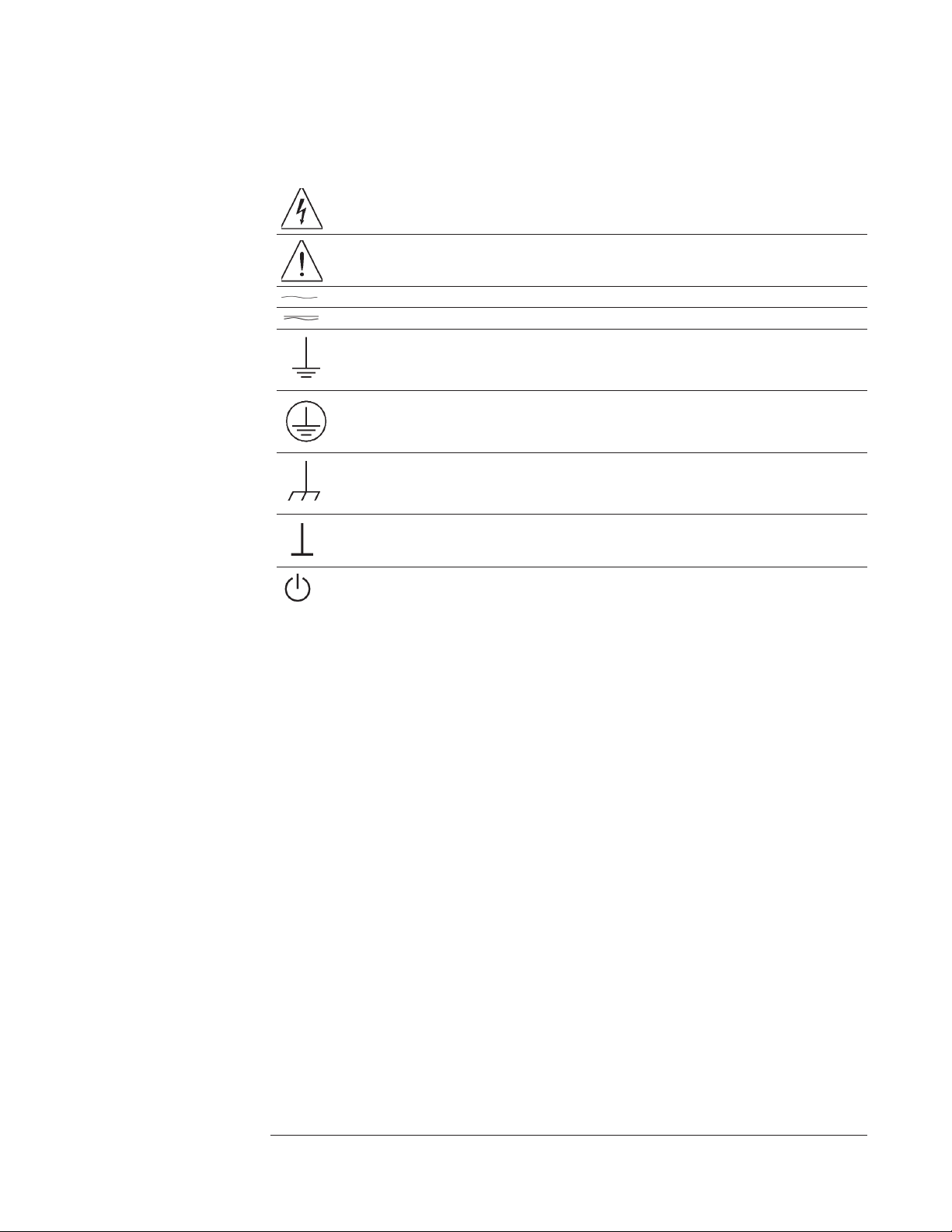
Safety Symbols
Warning, risk of electric shock
Caution, refer to accompanying documents
Alternating current
Both direct and alternating current
Earth (ground) terminal
Protective earth (ground) terminal
Frame or chassis terminal
Terminal is at earth potential.
Standby (supply). Units with this symbol are not completely disconnected from ac mains when
this switch is off
Page 5

TABLE OF CONTENTS
CHAPTER 1: GPIB Programming with the Agilent 35670A
GPIB Setup .................................................1-2
Configuring the GPIB System ......................................1-2
Quick Verification ............................................1-5
Verification Program ...........................................1-7
How the Agilent 35670A Operates in an GPIB System ..........................1-8
Controller Capabilities ..........................................1-8
GPIB Commands That Require Passing Control to the Agilent 35670A ................1-8
GPIB Interface Capabilities........................................1-9
GPIB Queues in the Agilent 35670A ...................................1-10
Command Synchronization ........................................1-10
Overlapped Commands in the Agilent 35670A .............................1-11
GPIB Commands That Transfer Mixed (ASCII/REAL) Data ......................1-12
Determining Units ............................................1-12
The Agilent 35670A’s Status Registers ..................................1-13
Register Summary ............................................1-13
Status Byte Register Set .........................................1-14
Device State Register Set .........................................1-16
Limit Fail Register Set ..........................................1-17
Questionable Status Register Set .....................................1-18
Questionable Voltage Register Set ....................................1-19
Standard Event Register Set .......................................1-20
Operation Status Register Set.......................................1-22
User Status Register Set .........................................1-24
Agilent 35670A Register Set Summary .................................1-25
SCPI Compliance Information .......................................1-26
Confirmed Commands ..........................................1-27
List of Approved Commands .......................................1-31
List of Instrument Specific Commands..................................1-32
CHAPTER 2: Introduction to the Command Reference
Finding the Right Command ........................................2-3
Command Syntax in the Agilent 35670A .................................2-5
Special Syntactic Elements ........................................2-5
Conventions................................................2-6
Syntax Descriptions............................................2-7
i
Page 6

CHAPTER 3: Common Commands
*CAL?query ...............................................3-2
*CLScommand .............................................3-3
*ESEcommand/query ..........................................3-4
*ESR?query ...............................................3-5
*IDN?query ...............................................3-6
*OPCcommand/query ..........................................3-7
*OPT?query ...............................................3-9
*PCBcommand .............................................3-10
*PSCcommand/query ..........................................3-11
*RSTcommand .............................................3-12
*SREcommand/query ..........................................3-14
*STB?query ...............................................3-16
*TRGcommand .............................................3-18
*TST?query ...............................................3-19
*WAIcommand .............................................3-20
CHAPTER 4: ABORt
ABORtcommand ............................................4-2
CHAPTER 5: ARM
ARM[:IMMediate]command ......................................5-2
ARM:RPM:INCRementcommand/query ................................5-3
ARM:RPM:MODEcommand/query...................................5-4
ARM:RPM:THResholdcommand/query ................................5-5
ARM:SOURcecommand/query .....................................5-6
ARM:TIMercommand/query ......................................5-8
CHAPTER 6: CALCulate
CALCulate[1|2|3|4]:ACTivecommand/query ..............................6-3
CALCulate[1|2|3|4]:CFIT:ABORtcommand ..............................6-4
CALCulate[1|2|3|4]:CFIT:COPYcommand ...............................6-5
CALCulate[1|2|3|4]:CFIT:DATAcommand/query ...........................6-6
CALCulate[1|2|3|4]:CFIT:DESTinationcommand/query ........................6-8
CALCulate[1|2|3|4]:CFIT:FREQuency[:AUTO]command/query ...................6-9
CALCulate[1|2|3|4]:CFIT:FREQuency:STARtcommand/query ....................6-10
CALCulate[1|2|3|4]:CFIT:FREQuency:STOPcommand/query .....................6-11
CALCulate[1|2|3|4]:CFIT:FSCalecommand/query ...........................6-12
CALCulate[1|2|3|4]:CFIT[:IMMediate]command ...........................6-13
CALCulate[1|2|3|4]:CFIT:ORDer:AUTOcommand/query .......................6-14
CALCulate[1|2|3|4]:CFIT:ORDer:POLescommand/query .......................6-15
CALCulate[1|2|3|4]:CFIT:ORDer:ZERoscommand/query .......................6-16
CALCulate[1|2|3|4]:CFIT:TDELaycommand/query ..........................6-17
CALCulate[1|2|3|4]:CFIT:WEIGht:AUTOcommand/query ......................6-18
CALCulate[1|2|3|4]:CFIT:WEIGht:REGistercommand/query .....................6-19
CALCulate[1|2|3|4]:DATA?query....................................6-20
CALCulate[1|2|3|4]:DATA:HEADer:POINts query ..........................6-22
CALCulate[1|2|3|4]:FEEDcommand/query ...............................6-23
CALCulate[1|2|3|4]:FORMatcommand/query .............................6-29
CALCulate[1|2|3|4]:GDAPerture:APERturecommand/query......................6-31
CALCulate[1|2|3|4]:LIMit:BEEP[:STATe]command/query ......................6-33
CALCulate[1|2|3|4]:LIMit:FAIL?query .................................6-34
CALCulate[1|2|3|4]:LIMit:LOWer:CLEar[:IMMediate]command ...................6-35
CALCulate[1|2|3|4]:LIMit:LOWer:MOVE:Ycommand ........................6-36
CALCulate[1|2|3|4]:LIMit:LOWer:REPort[:DATA]?query ......................6-37
CALCulate[1|2|3|4]:LIMit:LOWer:REPort:YDATa?query.......................6-38
CALCulate[1|2|3|4]:LIMit:LOWer:SEGMentcommand/query .....................6-39
ii
Page 7

CALCulate[1|2|3|4]:LIMit:LOWer:SEGMent:CLEarcommand ....................6-41
CALCulate[1|2|3|4]:LIMit:LOWer:TRACe[:IMMediate]command ..................6-42
CALCulate[1|2|3|4]:LIMit:STATecommand/query ...........................6-43
CALCulate[1|2|3|4]:LIMit:UPPer:CLEar[:IMMediate]command ...................6-44
CALCulate[1|2|3|4]:LIMit:UPPer:MOVE:Ycommand .........................6-45
CALCulate[1|2|3|4]:LIMit:UPPer:REPort[:DATA]?query .......................6-46
CALCulate[1|2|3|4]:LIMit:UPPer:REPort:YDATa?query .......................6-47
CALCulate[1|2|3|4]:LIMit:UPPer:SEGMentcommand/query .....................6-48
CALCulate[1|2|3|4]:LIMit:UPPer:SEGMent:CLEarcommand .....................6-50
CALCulate[1|2|3|4]:LIMit:UPPer:TRACe[:IMMediate]command ...................6-51
CALCulate[1|2|3|4]:MARKer:BAND:STARtcommand/query .....................6-52
CALCulate[1|2|3|4]:MARKer:BAND:STOPcommand/query .....................6-54
CALCulate[1|2|3|4]:MARKer:COUPled[:STATe]command/query ..................6-56
CALCulate[1|2|3|4]:MARKer:DTABle:CLEar[:IMMediate]command ................6-57
CALCulate[1|2|3|4]:MARKer:DTABle:COPY[1|2|3|4]command ...................6-58
CALCulate[1|2|3|4]:MARKer:DTABle[:DATA]?query ........................6-59
CALCulate[1|2|3|4]:MARKer:DTABle:X[:DATA]?query .......................6-61
CALCulate[1|2|3|4]:MARKer:DTABle:X:DELetecommand ......................6-62
CALCulate[1|2|3|4]:MARKer:DTABle:X:INSertcommand/query ...................6-63
CALCulate[1|2|3|4]:MARKer:DTABle:X:LABelcommand/query ...................6-64
CALCulate[1|2|3|4]:MARKer:DTABle:X:SELect[:POINt]command/query ..............6-65
CALCulate[1|2|3|4]:MARKer:FUNCtioncommand/query .......................6-66
CALCulate[1|2|3|4]:MARKer:FUNCtion:RESult?query ........................6-71
CALCulate[1|2|3|4]:MARKer:HARMonic:COUNtcommand/query ..................6-73
CALCulate[1|2|3|4]:MARKer:HARMonic:FUNDamentalcommand/query ..............6-74
CALCulate[1|2|3|4]:MARKer:MAXimum[:GLOBal]command ....................6-75
CALCulate[1|2|3|4]:MARKer:MAXimum[:GLOBal]:TRACkcommand/query ............6-76
CALCulate[1|2|3|4]:MARKer:MAXimum:LEFTcommand ......................6-77
CALCulate[1|2|3|4]:MARKer:MAXimum:RIGHtcommand ......................6-78
CALCulate[1|2|3|4]:MARKer:MODEcommand/query .........................6-79
CALCulate[1|2|3|4]:MARKer:POSitioncommand/query ........................6-80
CALCulate[1|2|3|4]:MARKer:POSition:POINtcommand/query ....................6-81
CALCulate[1|2|3|4]:MARKer:REFerence:Xcommand/query......................6-84
CALCulate[1|2|3|4]:MARKer:REFerence:Ycommand/query......................6-85
CALCulate[1|2|3|4]:MARKer:SIDeband:CARRiercommand/query ..................6-86
CALCulate[1|2|3|4]:MARKer:SIDeband:COUNtcommand/query ...................6-87
CALCulate[1|2|3|4]:MARKer:SIDeband:INCRementcommand/query.................6-88
CALCulate[1|2|3|4]:MARKer[:STATe]command/query ........................6-89
CALCulate[1|2|3|4]:MARKer:X[:ABSolute]command/query .....................6-90
CALCulate[1|2|3|4]:MARKer:X:RELativecommand/query ......................6-91
CALCulate[1|2|3|4]:MARKer:Y[:ABSolute]?query ..........................6-92
CALCulate[1|2|3|4]:MARKer:Y:RELativecommand/query ......................6-93
CALCulate[1|2|3|4]:MATH:CONStant[1|2|3|4|5]command/query ...................6-94
CALCulate[1|2|3|4]:MATH:DATAcommand/query ..........................6-95
CALCulate[1|2|3|4]:MATH[:EXPRession[1|2|3|4|5]]command/query .................6-97
CALCulate[1|2|3|4]:MATH:SELectcommand/query ..........................6-99
CALCulate[1|2|3|4]:MATH:STATecommand/query ..........................6-100
CALCulate[1|2|3|4]:SYNThesis:COPYcommand............................6-101
CALCulate[1|2|3|4]:SYNThesis:DATAcommand/query ........................6-102
CALCulate[1|2|3|4]:SYNThesis:DESTinationcommand/query.....................6-104
CALCulate[1|2|3|4]:SYNThesis:FSCalecommand/query ........................6-105
CALCulate[1|2|3|4]:SYNThesis:GAINcommand/query ........................6-106
CALCulate[1|2|3|4]:SYNThesis[:IMMediate]command ........................6-107
CALCulate[1|2|3|4]:SYNThesis:SPACingcommand/query.......................6-108
iii
Page 8

CALCulate[1|2|3|4]:SYNThesis:TDELaycommand/query .......................6-109
CALCulate[1|2|3|4]:SYNThesis:TTYPecommand/query ........................6-110
CALCulate[1|2|3|4]:UNIT:AMPLitudecommand/query ........................6-111
CALCulate[1|2|3|4]:UNIT:ANGLecommand/query ..........................6-113
CALCulate[1|2|3|4]:UNIT:DBReferencecommand/query .......................6-114
CALCulate[1|2|3|4]:UNIT:DBReference:IMPedancecommand/query .................6-115
CALCulate[1|2|3|4]:UNIT:DBReference:USER:LABelcommand/query................6-116
CALCulate[1|2|3|4]:UNIT:DBReference:USER:REFerencecommand/query .............6-117
CALCulate[1|2|3|4]:UNIT:MECHanicalcommand/query........................6-118
CALCulate[1|2|3|4]:UNIT:VOLTagecommand/query .........................6-119
CALCulate[1|2|3|4]:UNIT:Xcommand/query ..............................6-121
CALCulate[1|2|3|4]:UNIT:X:ORDer:FACTorcommand/query.....................6-123
CALCulate[1|2|3|4]:UNIT:X:USER:FREQuency:FACTorcommand/query ..............6-124
CALCulate[1|2|3|4]:UNIT:X:USER:FREQuency:LABelcommand/query ...............6-125
CALCulate[1|2|3|4]:UNIT:X:USER:TIME:FACTorcommand/query .................6-126
CALCulate[1|2|3|4]:UNIT:X:USER:TIME:LABelcommand/query ..................6-127
CALCulate[1|2|3|4]:WATerfall:COUNtcommand/query ........................6-128
CALCulate[1|2|3|4]:WATerfall[:DATA]?query ............................6-129
CALCulate[1|2|3|4]:WATerfall:SLICe:COPYcommand ........................6-131
CALCulate[1|2|3|4]:WATerfall:SLICe:SELectcommand/query ....................6-132
CALCulate[1|2|3|4]:WATerfall:SLICe:SELect:POINtcommand/query ................6-133
CALCulate[1|2|3|4]:WATerfall:TRACe:COPYcommand .......................6-135
CALCulate[1|2|3|4]:WATerfall:TRACe:SELectcommand/query....................6-136
CALCulate[1|2|3|4]:WATerfall:TRACe:SELect:POINtcommand/query ................6-137
CALCulate[1|2|3|4]:X:DATA?query ..................................6-138
CHAPTER 7: CALibration
CALibration[:ALL]?query .......................................7-2
CALibration:AUTOcommand/query ..................................7-3
CHAPTER 8: DISPlay
DISPlay:ANNotation[:ALL]command/query ..............................8-2
DISPlay:BODEcommand ........................................8-3
DISPlay:BRIGhtnesscommand/query ..................................8-4
DISPlay:ERRorcommand ........................................8-5
DISPlay:EXTernal[:STATe]command/query ..............................8-6
DISPlay:FORMatcommand/query ...................................8-7
DISPlay:GPIB:ECHOcommand/query .................................8-8
DISPlay:PROGram:KEY:BOXcommand/query ............................8-9
DISPlay:PROGram:KEY:BRACketcommand/query ..........................8-10
DISPlay:PROGram[:MODE]ommand/query ..............................8-11
DISPlay:PROGram:VECTor:BUFFer[:STATe]command/query ....................8-12
DISPlay:RPM[:STATe]command/query ................................8-13
DISPlay:SHOWall[:STATe]command/query ..............................8-14
DISPlay:STATecommand/query ....................................8-15
DISPlay:TCAPture:ENVelope[:STATe]command/query........................8-16
DISPlay:VIEWcommand/query .....................................8-17
DISPlay[:WINDow[1|2|3|4]]:DTABle:MARKer[:STATe]command/query ..............8-18
DISPlay[:WINDow[1|2|3|4]]:DTABle[:STATe]command/query....................8-19
DISPlay[:WINDow[1|2|3|4]]:LIMit:STATecommand/query ......................8-20
DISPlay[:WINDow[1|2|3|4]]:POLar:CLOCkwiseommand/query ...................8-21
DISPlay[:WINDow[1|2|3|4]]:POLar:ROTationcommand/query ....................8-22
DISPlay[:WINDow[1|2|3|4]]:TRACe:APOWer[:STATe]command/query...............8-24
DISPlay[:WINDow[1|2|3|4]]:TRACe:BPOWer[:STATe]command/query ...............8-25
DISPlay[:WINDow[1|2|3|4]]:TRACe:GRATicule:GRID[:STATe]command/query ..........8-26
DISPlay[:WINDow[1|2|3|4]]:TRACe:LABelcommand/query .....................8-27
iv
Page 9

DISPlay[:WINDow[1|2|3|4]]:TRACe:LABel:DEFault[:STATe]command/query ...........8-28
DISPlay[:WINDow[1|2|3|4]]:TRACe:X:MATCh[1|2|3|4]command ..................8-29
DISPlay[:WINDow[1|2|3|4]]:TRACe:X[:SCALe]:AUTOcommand/query...............8-30
DISPlay[:WINDow[1|2|3|4]]:TRACe:X[:SCALe]:LEFTcommand/query ...............8-31
DISPlay[:WINDow[1|2|3|4]]:TRACe:X[:SCALe]:RIGHtcommand/query...............8-32
DISPlay[:WINDow[1|2|3|4]]:TRACe:X:SPACingcommand/query ..................8-33
DISPlay[:WINDow[1|2|3|4]]:TRACe:Y:MATCh[1|2|3|4]command ..................8-34
DISPlay[:WINDow[1|2|3|4]]:TRACe:Y[:SCALe]:AUTOcommand/query...............8-35
DISPlay[:WINDow[1|2|3|4]]:TRACe:Y[:SCALe]:BOTTomcommand/query .............8-36
DISPlay[:WINDow[1|2|3|4]]:TRACe:Y[:SCALe]:CENTercommand/query ..............8-37
DISPlay[:WINDow[1|2|3|4]]:TRACe:Y[:SCALe]:PDIVisioncommand/query ............8-38
DISPlay[:WINDow[1|2|3|4]]:TRACe:Y[:SCALe]:REFerencecommand/query ............8-39
DISPlay[:WINDow[1|2|3|4]]:TRACe:Y[:SCALe]:TOPcommand/query ................8-41
DISPlay[:WINDow[1|2|3|4]]:TRACe:Y:SPACingommand/query ...................8-42
DISPlay[:WINDow[1|2|3|4]]:WATerfall:BASelinecommand/query ..................8-43
DISPlay[:WINDow[1|2|3|4]]:WATerfall:BOTTomcommand/query ..................8-44
DISPlay[:WINDow[1|2|3|4]]:WATerfall:COUNtcommand/query ...................8-45
DISPlay[:WINDow[1|2|3|4]]:WATerfall:HEIGhtcommand/query ...................8-46
DISPlay[:WINDow[1|2|3|4]]:WATerfall:HIDDencommand/query...................8-47
DISPlay[:WINDow[1|2|3|4]]:WATerfall:SKEWcommand/query ...................8-48
DISPlay[:WINDow[1|2|3|4]]:WATerfall:SKEW:ANGLecommand/query...............8-49
DISPlay[:WINDow[1|2|3|4]]:WATerfall[:STATe]command/query ..................8-50
DISPlay[:WINDow[1|2|3|4]]:WATerfall:TOPcommand/query.....................8-51
CHAPTER 9: FORMat
FORMat[:DATA]command/query ...................................9-2
CHAPTER 10: HCOPy
HCOPy:COLor:DEFaultcommand ...................................10-2
HCOPy:DESTinationcommand/query .................................10-3
HCOPy:DEVice:LANGuagecommand/query..............................10-4
HCOPy:DEVice:RESolutioncommand/query..............................10-5
HCOPy:DEVice:SPEedcommand/query ................................10-6
HCOPy[:IMMediate]command .....................................10-7
HCOPy:ITEM:FFEed:STATecommand/query .............................10-8
HCOPy:ITEM:LABel:COLorcommand/query .............................10-9
HCOPy:ITEM:LABel:STATecommand/query .............................10-10
HCOPy:ITEM:LABel:TEXTcommand/query .............................10-11
HCOPy:ITEM:TDSTamp:FORMatcommand/query ..........................10-12
HCOPy:ITEM:TDSTamp:STATecommand/query ...........................10-13
HCOPy:ITEM[:WINDow[1|2|3|4]]:TRACe:COLorcommand/query ..................10-14
HCOPy:ITEM[:WINDow[1|2|3|4]]:TRACe:GRATicule:COLorcommand/query ...........10-15
HCOPy:ITEM[:WINDow[1|2|3|4]]:TRACe:LIMit:LTYPecommand/query ..............10-16
HCOPy:ITEM[:WINDow[1|2|3|4]]:TRACe:LTYPecommand/query..................10-17
HCOPy:ITEM[:WINDow[1|2|3|4]]:TRACe:MARKer:COLorcommand/query ............10-18
HCOPy:PAGE:DIMensions:AUTOcommand/query ..........................10-19
HCOPy:PAGE:DIMensions:USER:LLEFtommand/query .......................10-20
HCOPy:PAGE:DIMensions:USER:URIGhtcommand/query......................10-22
HCOPy:PLOT:ADDResscommand/query ...............................10-23
HCOPy:PRINt:ADDResscommand/query ...............................10-24
HCOPy:TITLe[1|2]command/query...................................10-25
HCOPy:SOURcecommand/query ....................................10-26
v
Page 10

CHAPTER 11: INITiate
INITiate:CONTinuouscommand/query .................................11-2
INITiate[:IMMediate]command.....................................11-3
CHAPTER 12: INPut
INPut[1|2|3|4]:BIAS[:STATe]command/query .............................12-2
INPut[1|2|3|4]:COUPlingcommand/query................................12-3
INPut[1|2|3|4]:FILTer:AWEighting[:STATe]command/query .....................12-4
INPut[1|2|3|4]:FILTer[:LPASs][:STATe]command/query .......................12-5
INPut[1|2|3|4]:LOWcommand/query ..................................12-6
INPut[1|2|3|4]:REFerence:DIRectioncommand/query .........................12-7
INPut[1|2|3|4]:REFerence:POINtcommand/query ...........................12-8
INPut[1|2|3|4][:STATe]command/query ................................12-9
CHAPTER 13: INSTrument
INSTrument:NSELectcommand/query .................................13-2
INSTrument[:SELect]command/query .................................13-3
CHAPTER 14: MEMory
MEMory:CATalog[:ALL]?query ....................................14-2
MEMory:CATalog:NAME?query....................................14-3
MEMory:DELete:ALLcommand ....................................14-4
MEMory:DELete[:NAME]command ..................................14-5
MEMory:FREE[:ALL]?query ......................................14-6
CHAPTER 15: MMEMory
MMEMory:COPYcommand ......................................15-3
MMEMory:DELeteommand ......................................15-4
MMEMory:DISK:ADDResscommand/query ..............................15-5
MMEMory:DISK:UNITcommand/query ................................15-6
MMEMory:FSYStem?query ......................................15-7
MMEMory:INITializecommand ....................................15-8
MMEMory:LOAD:CFITcommand ...................................15-10
MMEMory:LOAD:CONTinuecommand/query.............................15-11
MMEMory:LOAD:DTABle:TRACe[1|2|3|4]command ........................15-12
MMEMory:LOAD:LIMit:LOWer:TRACe[1|2|3|4]command .....................15-13
MMEMory:LOAD:LIMit:UPPer:TRACe[1|2|3|4]command ......................15-14
MMEMory:LOAD:MATHcommand ..................................15-15
MMEMory:LOAD:PROGramcommand ................................15-16
MMEMory:LOAD:STATecommand ..................................15-17
MMEMory:LOAD:SYNThesiscommand ................................15-18
MMEMory:LOAD:TCAPturecommand ................................15-19
MMEMory:LOAD:TRACecommand ..................................15-20
MMEMory:LOAD:WATerfallcommand ................................15-21
MMEMory:MDIRectorycommand ...................................15-22
MMEMory:MOVEcommand ......................................15-23
MMEMory:MSIScommand/query ...................................15-24
MMEMory:NAMEcommand/query...................................15-25
MMEMory:STORe:CFITcommand ...................................15-26
MMEMory:STORe:CONTinuecommand/query ............................15-27
MMEMory:STORe:DTABle:TRACe[1|2|3|4]command ........................15-28
MMEMory:STORe:LIMit:LOWer:TRACe[1|2|3|4]command .....................15-29
MMEMory:STORe:LIMit:UPPer:TRACe[1|2|3|4]command ......................15-30
MMEMory:STORe:MATHcommand ..................................15-31
MMEMory:STORe:PROGramommand.................................15-32
MMEMory:STORe:PROGram:FORMatcommand/query .......................15-33
MMEMory:STORe:STATecommand ..................................15-34
MMEMory:STORe:SYNThesiscommand ...............................15-35
vi
Page 11

MMEMory:STORe:TCAPturecommand ................................15-36
MMEMory:STORe:TRACecommand .................................15-37
MMEM:STORe:TRACe:FORMatcommand/query ...........................15-38
MMEMory:STORe:WATerfallcommand ................................15-39
CHAPTER 16: OUTPut
OUTPut:FILTer[:LPASs][:STATe]command/query ..........................16-2
OUTPut[:STATe]command/query ...................................16-3
CHAPTER 17: PROGram
PROGram:EDIT:ENABlecommand/query ...............................17-2
PROGram:EXPLicit:DEFinecommand/query..............................17-3
PROGram:EXPLicit:LABelcommand/query ..............................17-4
PROGram[:SELected]:DEFinecommand/query ............................17-5
PROGram[:SELected]:DELete:ALLcommand .............................17-6
PROGram[:SELected]:DELete[:SELected]command .........................17-7
PROGram[:SELected]:LABelcommand/query .............................17-8
PROGram[:SELected]:MALLocatecommand/query ..........................17-9
PROGram[:SELected]:NAMEcommand/query .............................17-10
PROGram[:SELected]:NUMBercommand/query............................17-11
PROGram[:SELected]:STATecommand/query .............................17-12
PROGram[:SELected]:STRingcommand/query ............................17-13
CHAPTER 18: [SENSe:]
[SENSe:]AVERage:CONFidencecommand/query ...........................18-2
[SENSe:]AVERage:COUNtcommand/query ..............................18-3
[SENSe:]AVERage:HOLDcommand/query ..............................18-4
[SENSe:]AVERage:IMPulsecommand/query..............................18-5
[SENSe:]AVERage:IRESult:RATEcommand/query ..........................18-6
[SENSe:]AVERage:IRESult[:STATe]command/query.........................18-7
[SENSe:]AVERage:PREViewcommand/query .............................18-8
[SENSe:]AVERage:PREView:ACCeptcommand ...........................18-9
[SENSe:]AVERage:PREView:REJectommand.............................18-10
[SENSe:]AVERage:PREView:TIMEcommand/query .........................18-11
[SENSe:]AVERage[:STATe]and/query.................................18-12
[SENSe:]AVERage:TCONtrolcommand/query.............................18-14
[SENSe:]AVERage:TIMEcommand/query ...............................18-17
[SENSe:]AVERage:TYPEcommand/query ...............................18-19
[SENSe:]DATAcommand/query ....................................18-21
[SENSE:]DATA:HEADer:FREQuency:STARt?query .........................18-22
[SENSE:]DATA:HEADer:FREQuency:STOP?query .........................18-23
[SENSE:]DATA:HEADer:POINtsquery ................................18-24
[SENSe:]DATA:RANGecommand/query................................18-25
[SENSe:]FEEDcommand/query.....................................18-26
[SENSe:]FREQuency:BLOCksizecommand/query ...........................18-27
[SENSe:]FREQuency:CENTercommand/query ............................18-29
[SENSe:]FREQuency:MANualcommand/query ............................18-30
[SENSe:]FREQuency:RESolutioncommand/query ...........................18-31
[SENSe:]FREQuency:RESolution:AUTOcommand/query .......................18-34
[SENSe:]FREQuency:RESolution:AUTO:MCHangecommand/query .................18-36
[SENSe:]FREQuency:RESolution:AUTO:MINimumcommand/query.................18-37
[SENSe:]FREQuency:RESolution:OCTavecommand/query ......................18-38
[SENSe:]FREQuency:SPANcommand/query..............................18-40
[SENSe:]FREQuency:SPAN:FULLcommand .............................18-43
[SENSe:]FREQuency:SPAN:LINKcommand/query ..........................18-45
[SENSe:]FREQuency:STARtcommand/query .............................18-46
[SENSe:]FREQuency:STEP[:INCRement]command/query ......................18-48
vii
Page 12

[SENSe:]FREQuency:STOPcommand/query ..............................18-49
[SENSe:]HISTogram:BINSommand/query ...............................18-50
[SENSe:]ORDer:MAXimumcommand/query..............................18-51
[SENSe:]ORDer:RESolutioncommand/query..............................18-52
[SENSe:]ORDer:RESolution:TRACkcommand/query .........................18-53
[SENSe:]ORDer:RPM:MAXimumommand/query ...........................18-54
[SENSe:]ORDer:RPM:MINimumcommand/query ...........................18-55
[SENSe:]ORDer:TRACk[1|2|3|4|5]command/query ..........................18-56
[SENSe:]ORDer:TRACk[1|2|3|4|5]:STATecommand/query ......................18-57
[SENSe:]REFerencecommand/query ..................................18-58
[SENSe:]REJect:STATecommand/query ................................18-59
[SENSe:]SWEep:DIRectioncommand/query ..............................18-60
[SENSe:]SWEep:DWELlommand/query ................................18-61
[SENSe:]SWEep:MODEcommand/query................................18-62
[SENSe:]SWEep:OVERlapcommand/query ..............................18-63
[SENSe:]SWEep:SPACingcommand/query ..............................18-65
[SENSe:]SWEep:STIMecommand/query ................................18-66
[SENSe:]SWEep:TIMEcommand/query ................................18-67
[SENSe:]TCAPture:ABORtommand ..................................18-68
[SENSe:]TCAPture:DELetecommand .................................18-69
[SENSe:]TCAPture:FILEommand/query ................................18-70
[SENSe:]TCAPture[:IMMediate]command...............................18-71
[SENSe:]TCAPture:LENGthcommand/query..............................18-72
[SENSe:]TCAPture:MALLocatecommand ...............................18-74
[SENSe:]TCAPture:STARt[1|2|3|4]command/query ..........................18-75
[SENSe:]TCAPture:STOP[1|2|3|4]command/query ..........................18-76
[SENSe:]TCAPture:TACHometer:RPM:MAXimumommand/query..................18-77
[SENSe:]TCAPture:TACHometer[:STATe]command/query......................18-78
[SENSe:]VOLTage[1|2|3|4][:DC]:RANGe:AUTOommand/query ...................18-79
[SENSe:]VOLTage[1|2|3|4][:DC]:RANGe:AUTO:DIRectioncommand/query ............18-81
[SENSe:]VOLTage[1|2|3|4][:DC]:RANGe:UNIT:USER:LABelcommand/query ...........18-82
[SENSe:]VOLTage[1|2|3|4][:DC]:RANGe:UNIT:USER:SFACtorcommand/query ..........18-83
[SENSe:]VOLTage[1|2|3|4][:DC]:RANGe:UNIT:USER[:STATe]command/query ..........18-84
[SENSe:]VOLTage[1|2|3|4][:DC]:RANGe:UNIT:XDCR:LABelcommand/query ...........18-85
[SENSe:]VOLTage[1|2|3|4][:DC]:RANGe[:UPPer]command/query..................18-86
[SENSe:]WINDow[1|2|3|4]:EXPonentialcommand/query .......................18-87
[SENSe:]WINDow[1|2|3|4]:FORCecommand/query ..........................18-88
[SENSe:]WINDow[1|2|3|4]:ORDer:DCcommand/query ........................18-89
[SENSe:]WINDow[1|2|3|4][:TYPE]command/query ..........................18-90
CHAPTER 19: SOURce
SOURce:BURStcommand/query ....................................19-2
SOURce:FREQuency[:CW]command/query ..............................19-3
SOURce:FREQuency:FIXedcommand/query..............................19-4
SOURce:FUNCtion[:SHAPe]command/query .............................19-5
SOURce:USER:CAPTurecommand/query ...............................19-6
SOURce:USER[:REGister]ommand/query ...............................19-7
SOURce:USER:REPeatcommand/query ................................19-8
SOURce:VOLTage[:LEVel]:AUTOcommand/query ..........................19-9
SOURce:VOLTage[:LEVel][:IMMediate][:AMPLitude]command/query ...............19-10
SOURce:VOLTage[:LEVel][:IMMediate]:OFFSetcommand/query ..................19-11
SOURce:VOLTage[:LEVel]:REFerencecommand/query .......................19-12
SOURce:VOLTage[:LEVel]:REFerence:CHANnelcommand/query ..................19-13
SOURce:VOLTage[:LEVel]:REFerence:TOLerancecommand/query .................19-14
SOURce:VOLTage:LIMit[:AMPLitude]command/query .......................19-15
viii
Page 13

SOURce:VOLTage:LIMit:INPutcommand/query ...........................19-16
SOURce:VOLTage:SLEWcommand/query...............................19-17
CHAPTER 20: STATus
STATus:DEVice:CONDition?query ..................................20-2
STATus:DEVice:ENABlecommand/query ...............................20-3
STATus:DEVice[:EVENt]?query ....................................20-4
STATus:DEVice:NTRansitioncommand/query.............................20-5
STATus:DEVice:PTRansitioncommand/query .............................20-6
STATus:OPERation:CONDition?query.................................20-7
STATus:OPERation:ENABlecommand/query .............................20-8
STATus:OPERation[:EVENt]?query ..................................20-9
STATus:OPERation:NTRansitioncommand/query ...........................20-10
STATus:OPERation:PTRansitioncommand/query ...........................20-11
STATus:PRESetcommand .......................................20-12
STATus:QUEStionable:CONDition?query ...............................20-13
STATus:QUEStionable:ENABlecommand/query ...........................20-14
STATus:QUEStionable[:EVENt]?query ................................20-15
STATus:QUEStionable:LIMit:CONDition?query ...........................20-16
STATus:QUEStionable:LIMit:ENABlecommand/query ........................20-17
STATus:QUEStionable:LIMit[:EVENt]?query .............................20-18
STATus:QUEStionable:LIMit:NTRansitioncommand/query......................20-19
STATus:QUEStionable:LIMit:PTRansitioncommand/query ......................20-20
STATus:QUEStionable:NTRansitioncommand/query .........................20-21
STATus:QUEStionable:PTRansitioncommand/query .........................20-22
STATus:QUEStionable:VOLTage:CONDition?query .........................20-23
STATus:QUEStionable:VOLTage:ENABlecommand/query ......................20-24
STATus:QUEStionable:VOLTage[:EVENt]?query ..........................20-25
STATus:QUEStionable:VOLTage:NTRansitioncommand/query ...................20-26
STATus:QUEStionable:VOLTage:PTRansitioncommand/query....................20-27
STATus:USER:ENABlecommand/query ................................20-28
STATus:USER[:EVENt]?query.....................................20-29
STATus:USER:PULSecommand ....................................20-30
CHAPTER 21: SYSTem
SYSTem:BEEPer[:IMMediate]command ................................21-2
SYSTem:BEEPer:STATecommand/query ...............................21-3
SYSTem:COMMunicate:GPIB[:SELF]:ADDResscommand/query ..................21-4
SYSTem:COMMunicate:SERial[:RECeive]:BAUDcommand/query .................21-5
SYSTem:COMMunicate:SERial[:RECeive]:BITScommand/query ..................21-6
SYSTem:COMMunicate:SERial[:RECeive]:PACEcommand/query ..................21-7
SYSTem:COMMunicate:SERial[:RECeive]:PARity:CHECkcommand/query.............21-8
SYSTem:COMMunicate:SERial[:RECeive]:PARity[:TYPE]command/query.............21-9
SYSTem:COMMunicate:SERial[:RECeive]:SBITscommand/query ..................21-10
SYSTem:COMMunicate:SERial:TRANsmit:PACEcommand/query..................21-11
SYSTem:DATEcommand/query ....................................21-12
SYSTem:ERRor?query .........................................21-13
SYSTem:FAN[:STATe]command/query ................................21-14
SYSTem:FLOG:CLEarcommand ....................................21-15
SYSTem:KEYcommand/query .....................................21-16
SYSTem:KLOCkcommand/query....................................21-21
SYSTem:POWer:SOURce?query ....................................21-22
SYSTem:POWer:STATecommand/query................................21-23
SYSTem:PRESetcommand .......................................21-24
SYSTem:SETcommand/query .....................................21-25
SYSTem:TIMEcommand/query.....................................21-26
ix
Page 14

SYSTem:VERSion?query ........................................21-27
CHAPTER 22: TEST
TEST:LOG:CLEarcommand ......................................22-2
TEST:LONGcommand .........................................22-3
TEST:LONG:RESult?query.......................................22-4
CHAPTER 23: TRACe
TRACe[:DATA]command/query ....................................23-2
TRACe:WATerfall[:DATA]command/query ..............................23-5
TRACe:X[:DATA]?query ........................................23-7
TRACe:X:UNIT?query .........................................23-8
TRACe:Z[:DATA]query ........................................23-9
TRACe:Z:UNIT?query .........................................23-10
CHAPTER 24: TRIGger
TRIGger:EXTernal:FILTer[:LPAS][:STATe]command/query .....................24-2
TRIGger:EXTernal:LEVelcommand/query ...............................24-3
TRIGger:EXTernal:RANGecommand/query ..............................24-4
TRIGger[:IMMediate]command ....................................24-5
TRIGger:LEVelcommand/query ....................................24-6
TRIGger:SLOPecommand/query ....................................24-7
TRIGger:SOURcecommand/query ...................................24-8
TRIGger:STARt[1|2|3|4]command/query ................................24-10
TRIGger:TACHometer:HOLDoffcommand/query ...........................24-12
TRIGger:TACHometer:LEVelcommand/query.............................24-13
TRIGger:TACHometer:PCOuntcommand/query ............................24-14
TRIGger:TACHometer:RANGecommand/query ............................24-15
TRIGger:TACHometer[:RPM]?query..................................24-16
TRIGger:TACHometer:SLOPecommand/query ............................24-17
APPENDIX A: Agilent 35670A Command Summary
Command List ...............................................A-1
APPENDIX B: Cross-Reference from Front-Panel Keys to GPIB Commands
Measurement Group ............................................B-2
Display Group ...............................................B-9
Marker Group ................................................B-18
System Group ................................................B-21
x
Page 15

APPENDIX C: Error Messages
Command Errors ..............................................C-2
Execution Errors ..............................................C-3
Device-Specific Errors ...........................................C-10
Query Errors ................................................C-11
APPENDIX D: Instrument Modes
APPENDIX E: Determining Units
APPENDIX F: Example Programs
INDEX
xi
Page 16

Page 17

GPIB Programming with the Agilent 35670A
1
Page 18

Page 19
1
GPIB Programming with the Agilent 35670A
In This Book
This is GPIB Programming with the Agilent 35670A. It contains the command syntax, structure and a
detailed description of each GPIB command available for the Agilent 35670A. In addition, it contains
instrument-specific information not available in the GPIB Programmer’s Guide.
For an introduction to GPIB programming, read the GPIB Programmer’s Guide. It is intended for people
not familiar with GPIB programming or remote control of an instrument. The book introduces the basic
concepts of GPIB programming and describes the Standard Commands for Programmable Instruments
(SCPI). In addition, it describes how to operate an instrument in an GPIB system and how to transfer data
between an external controller and an instrument.
Chapter 1 presents GPIB programming information specific to the Agilent 35670A. It includes:
How to setup the Agilent 35670A to an external controller and how to verify it works.
A description of the Agilent 35670A’s input, output and error queues.
A listing of GPIB commands that require synchronization or passing control.
A description of each of the Agilent 35670A’s status registers.
A listing of all SCPI commands.
Chapter 2 describes the conventions and syntax descriptions used in the command reference chapters, and
a section on finding commands.
Chapters 3 - 24, the Command Reference, contain a detailed description of each GPIB command. The
commands are organized alphabetically. A chapter introduction describes the SCPI subsystem and where
it fits in the flow of control and measurement data within the Agilent 35670A.
The appendices, A - F, contain a variety of reference material:
Appendix A provides a quick reference to the Agilent 35670A’s GPIB command set.
Appendix B provides a cross reference of the Agilent 35670A’s hardkeys and softkeys and their
equivalent GPIB commands.
Appendix C provides a complete listing of the Agilent 35670A’s error messages.
Appendix D provides a list of valid GPIB commands for each of the major instrument modes.
Appendix E explains how to determine the Y-axis units you send with certain commands.
Appendix F lists some of the example programs for the Agilent 35670A that appear on the Agilent
35670A Example Programs Disk. The example programs demonstrate how to transfer data between
the Agilent 35670A and an external controller.
Included in the documentation set is the “Agilent 35670A GPIB Commands: Quick Reference.” This
card provides quick and convenient access to command syntax and structure.
1-1
Page 20
GPIB Setup
GPIB Setup
This section contains a procedure for configuring the Agilent 35670A and an external controller in a
simple GPIB system. Although an HP 9000 Series 340 computer is the controller used in the system,
other computers that support an GPIB interface can also be used. If you are using one of those other
computers, the configuration procedure can only be used as a general guide. You should consult your
computer’s documentation for more complete information.
This section also contains a procedure for verifying that commands can be sent over the GPIB. BASIC is
used for the verification procedure’s test program. If your computer uses some other language, the
keywords and syntax for the test program may be different. You will need to write a similar program
using your language’s keywords and syntax.
Configuring the GPIB System
Equipment and Software
Agilent 35670A Dynamic Signal Analyzer
HP 9000 Series 340 computer
Agilent 10833A, B, C, or D GPIB Cable
BASIC
Procedure
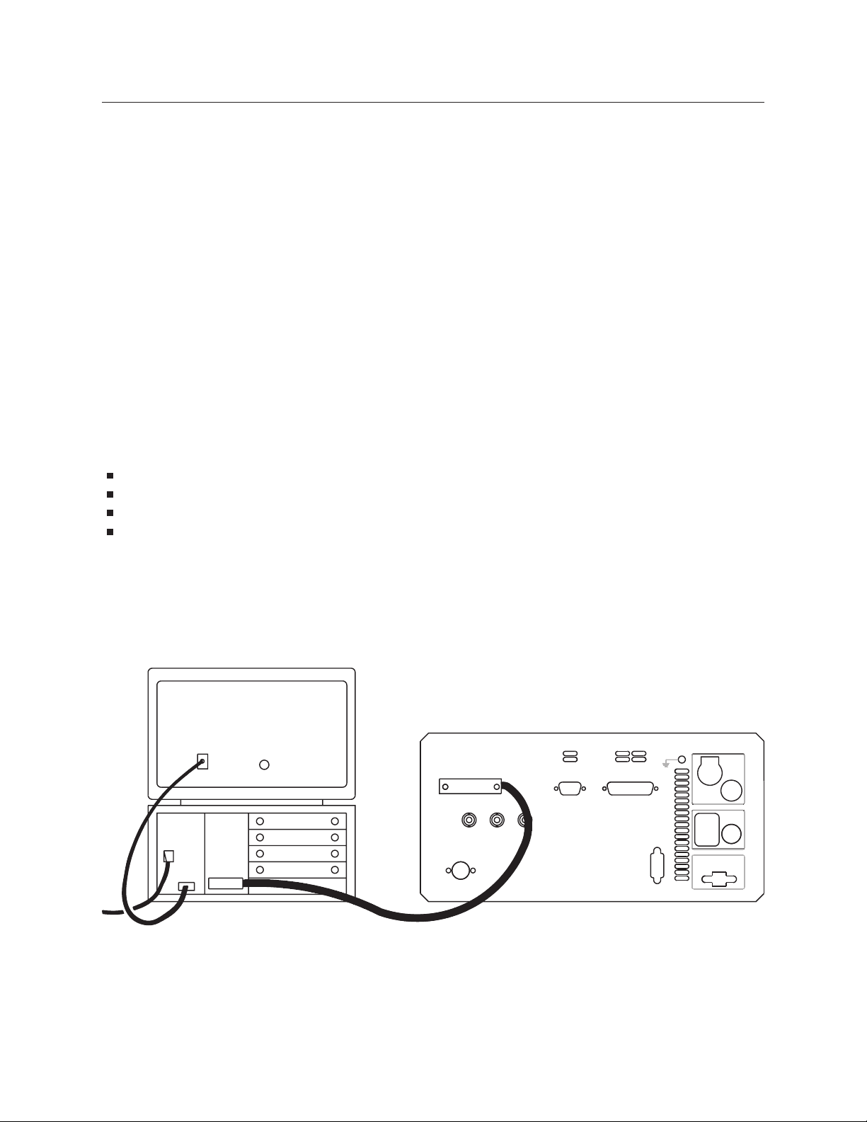
Turn off the Agilent 35670A and the HP 9000 Series 340, then connect them with the GPIB
cable as shown in figure 1-1.
1-2
3-1. GPIB Connections
Page 21
GPIB Setup
1. 1. Turn on the HP 9000 Series 340. If necessary, load BASIC following the instructions in the
computer’s operating manual. Note that the following language extensions must be installed for the
verification program to work:
CRTA
–
GPIB
–
IO
–
EDIT
–
Programs that are more complex than the verification program will probably require more language
extensions. For a complete list of loaded language extensions, enter the following BASIC
command into your computer:
LIST BIN
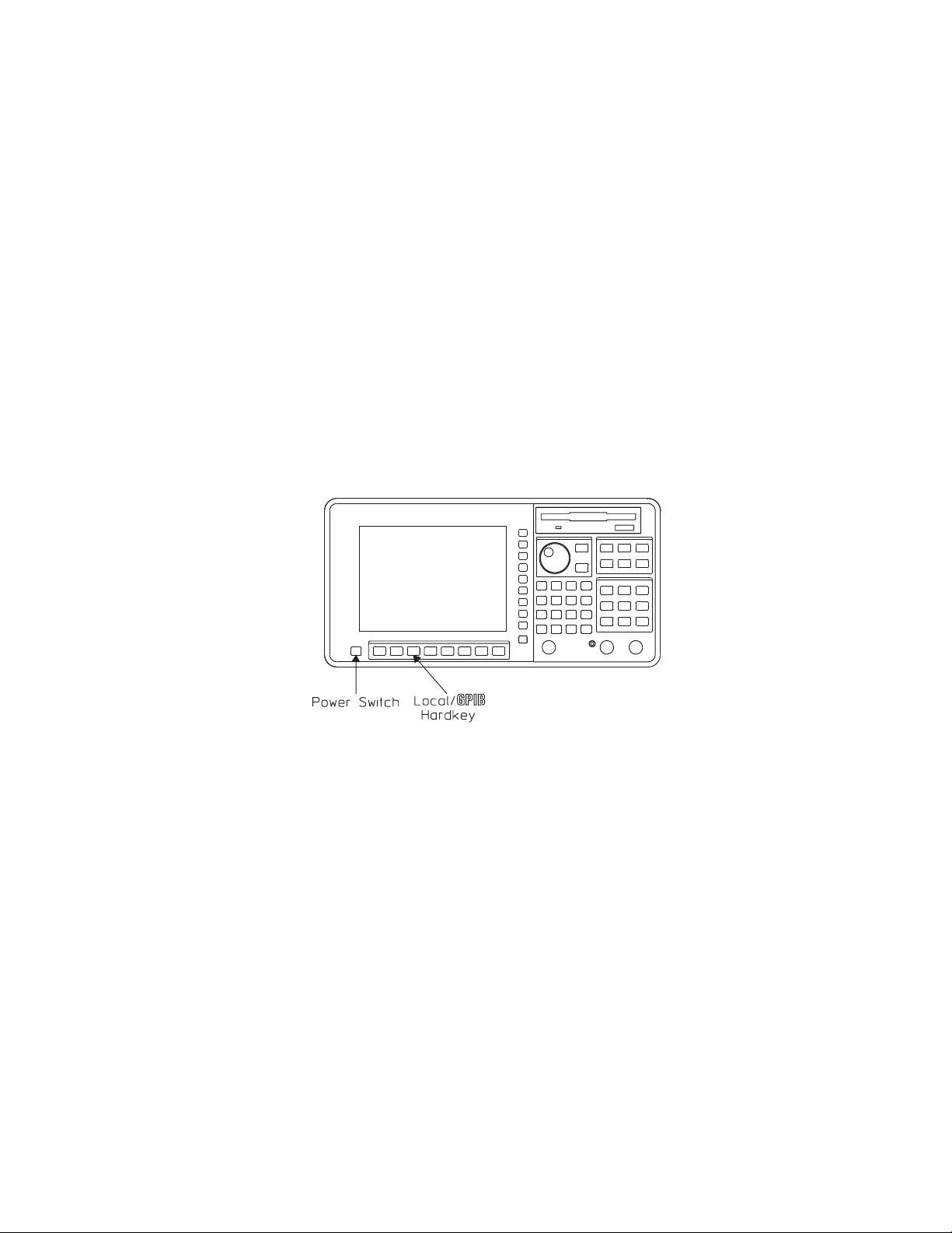
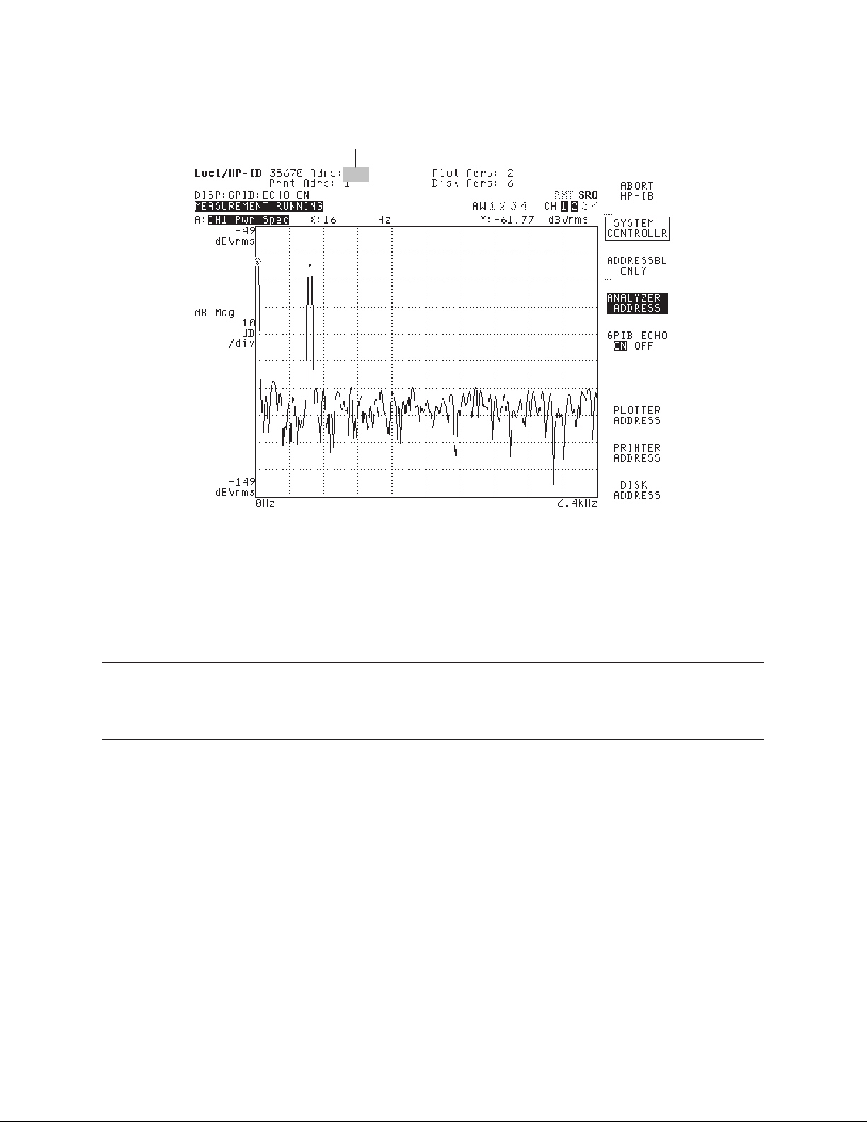
Turn on the Agilent 35670A. When the softkey labels appear, press the [ Local/GPIB ] hardkey.
See figure 1-2.
1-2. Agilent 35670A Front Panel
Verify that the analyzer’s address is set to 11. The current address setting is displayed when you
press the [
[
ANALYZER ADDRESS
ANALYZER ADDRESS
], then using the numeric keypad and the [
] softkey (see figure 1-3). You can change the address by pressing
] softkey to enter a new value.
ENTER
However, the instructions in the verification procedure assume that the analyzer address is set to 11.
1-3
Page 22
GPIB Setup
Analyzer’s Address
3-3. Agilent 35670A Screen After Pressing Local/GPIB
Verify that the analyzer is set to the addressable-only mode. The softkey labels that appear when
you press the [ Local/GPIB ] hardkey include [
SYSTEM CONTROLLR
] and [
ADDRESSBL ONLY
]. Only
one of these two softkeys can be selected at a time, and the one that is selected will have a box
around it. Press [
ADDRESSBL ONLY
] if it is not selected.
Note In any GPIB system there can be more than one device with controller capabilities. But
at any given time, only one device on the bus can be designated as the system controller.
See the GPIB Programmer’s Guide for more information about controller capabilities.
1-4
Page 23
GPIB Setup
Quick Verification
Having just completed all the steps in the preceding section, you are ready to verify that commands can
be sent over the GPIB. In this quick verification, you are going to enter an BASIC keyword that should
place the Agilent 35670A under remote control.
Procedure
Type the following on the computer:
REMOTE 711
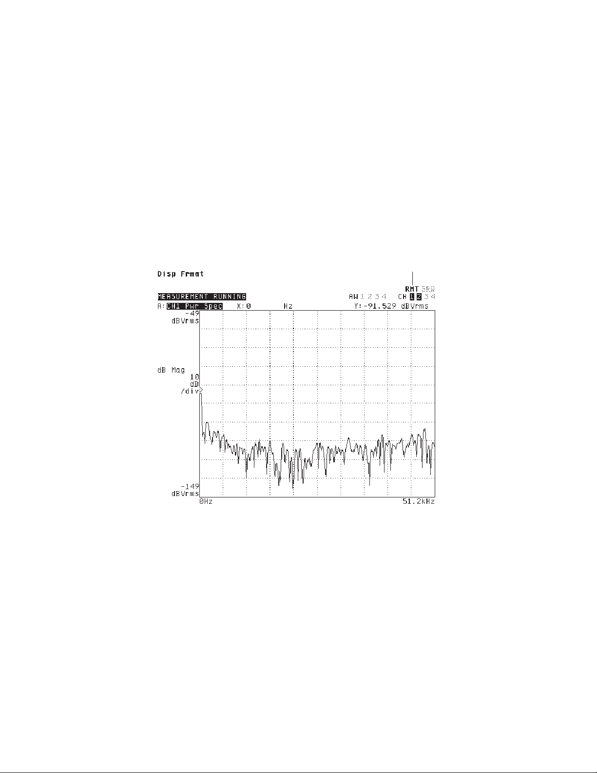
then press the computer’s ENTER key. The RMT indicator should appear highlighted at the top of
the Agilent 35670A’s screen (see figure 1-4). This tells you that the analyzer is under remote
control of the computer.
3-4. RMT (Remote) Indicator
Remote Indicator
Now type the following on the computer:
LOCAL 711
then press the computer’s ENTER key. The RMT indicator should become “ghosted.” That is, the
word is still readable, but no longer highlighted. This tells you that the analyzer has been returned
to front-panel control.
1-5
Page 24

GPIB Setup
Troubleshooting
If the RMT indicator does not perform as expected, check the following:
Be sure that your GPIB cable connections are secure and that the cable is free of defects.
Verify that the analyzer is in addressable-only mode and that its address is set to 11.
Be sure you are using the required equipment and software.
Be sure you have loaded all the required language extensions into the computer. (For a list of loaded
extensions, enter the following into the computer: LIST BIN)
If everything seems to be in order, but the RMT indicator still doesn’t perform as expected, follow the
procedure in “Need Assistance?,” that appears on the last page of this book.
1-6
Page 25

GPIB Setup
Verification Program
The quick verification procedure confirmed that the computer could talk to the analyzer. However, you
must write a short program to confirm that the analyzer can talk to the computer. If you enter the
program correctly, the computer displays the following statement when you run the program:
FREQUENCY SPAN IS: 51200 HZ
Note The following procedure assumes that you have completed all the steps in “Configuring
the GPIB System” using all the required equipment and software.
Procedure
Enter the following program:
10 PRINTER IS 1
20 ASSIGN @Agilent35670A TO 711
30 ABORT 7
40 CLEAR @Agilent35670A
50 OUTPUT @Agilent35670A;"*RST"
60 OUTPUT @Agilent35670A;"SENS:FREQ:SPAN:FULL"
70 OUTPUT @Agilent35670A;"SENS:FREQ:SPAN?"
80 ENTER @Agilent35670A;A
90 PRINT “FREQUENCY SPAN IS:”;A;"HZ"
100 END
See your computer and software documentation if you need help entering the program.
RUN the program. The program tells the analyzer to reset. It then tells the analyzer to select its widest
frequency span. Finally, the program asks the analyzer to return the value of the widest span and has the
computer display the returned value as follows:
FREQUENCY SPAN IS: 51200 HZ
Troubleshooting
If the program does not run correctly, be sure you have entered the program exactly as listed. Then go
back to “Quick Verification” for additional troubleshooting hints.
1-7
Page 26

How the Agilent 35670A Operates in an GPIB System
How the Agilent 35670A Operates in an GPIB System
This section provides instrument-specific information for the operation of the Agilent 35670A in an GPIB
system. For a general overview of how an analyzer operates in an GPIB system, see the GPIB
Programmer’s Guide.
Controller Capabilities
The Agilent 35670A can be configured as an GPIB system controller or as an addressable-only GPIB
device. To configure the analyzer, press the [ Local/GPIB ] key on the front panel. To configure the
analyzer as the GPIB system controller press [
configure the Agilent 35670A as an addressable-only device on the bus, press [
Normally, the Agilent 35670A is not configured as the system controller unless it is the only controller on
the bus. Such a setup would be likely if you only wanted to control printers or plotters with the analyzer.
It might also be the case if you were using Instrument BASIC to control other test equipment.
When the analyzer is used with another controller on the bus, it is normally configured as an
addressable-only GPIB device. In this configuration, when the analyzer is passed control it can function
as the active controller. It can also function as a talker or listener.
SYSTEM CONTROLLR
] which appears in the softkey menu. To
ADDRESSBL ONLY
].
GPIB Commands That Require Passing Control to the Agilent 35670A
If there is more than one controller on the bus, the Agilent 35670A needs to have active control (instead
of system control) to initiate operations such as plotting. The Agilent 35670A must be the active
controller for the following GPIB commands:
HCOPy[:IMMediate]
HCOPy:ITEM:ALL[:IMMediate]
HCOPy:ITEM[:WINDOW[1|2|3|4]]:TRACe:GRATicule[:IMMediate]
HCOPy:ITEM[:WINDOW[1|2|3|4]]:TRACe[:IMMediate]
HCOPy:ITEM[:WINDOW[1|2|3|4]]:TRACe:MARKer[:IMMediate]
HCOPy:ITEM[:WINDOW[1|2|3|4]]:TRACe:MARKer:REFerence[:IMMediate]
MMEMory:COPY
MMEMory:DELete
MMEMory:INITialize
MMEMory:MSIS
MMEMory:MOVE
See the GPIB Programmer’s Guide, for more information and examples about passing control to an
analyzer.
1-8
Page 27

How the Agilent 35670A Operates in an GPIB System
GPIB Interface Capabilities
The Agilent 35670A has the following interface capabilities, as defined by the IEEE 488.1 standard:
SH1 full Source handshake capability
AH1 full Acceptor handshake capability
T6 basic Talker, Serial Poll, no Talk Only, unaddress if MLA
TE0 no Extended Talker capability
L4 basic Listener, no Listen Only, unaddress if MTA
LE0 no Extended Listener capability
SR1 full Service Request capability
RL1 full Remote/Local capability
PP0* Parallel Poll capability
DC1 full Device Clear capability
DT1 full Device Trigger capability
C1 System Controller capability
C2 send IFC and take charge Controller capability
C3 send REN Controller capability
C4* respond to SRQ
C6* send IFC, receive control, pass control, parallel poll, pass control to self
C10* send IFC, receive control, pass control, parallel poll
C12 send IF messages, receive control, pass control
E2 tri-state drivers
* only when an Instrument BASIC program is running
1-9
Page 28

How the Agilent 35670A Operates in an GPIB System
GPIB Queues in the Agilent 35670A
Queues enhance the exchange of messages between the Agilent 35670A and other devices on the bus.
The Agilent 35670 contains three queues.
The input queue holds up to 128 bytes.
The error queue temporarily stores up to 5 error messages.
The output queue temporarily stores a single response message until it is read by a controller.
For additional information about the use of queues in exchanging messages between an analyzer and an
external controller, see the GPIB Programmer’s Guide.
Command Synchronization
Device commands can be divided into two broad classes:
sequential commands
overlapped commands
Most device commands that you send to the analyzer are processed sequentially. A sequential command
holds off the processing of subsequent commands until it has been completely processed. Some
commands do not hold off the processing of subsequent commands. These are called overlapped
commands and in many situations they require synchronization.
See the GPIB Programmer’s Guide for more information and examples about command synchronization.
1-10
Page 29

How the Agilent 35670A Operates in an GPIB System
Overlapped Commands in the Agilent 35670A
The Agilent 35670A has the following overlapped commands that require synchronization:
CALCulate[1|2|3|4]:CFIT[:IMMediate]
CALCulate[1|2|3|4]:FEED
CALCulate[1|2|3|4]:FORMat
CALCulate[1|2|3|4]:SYNThesis[:IMMediate]
CALCulate[1|2|3|4]:UNIT:AMPLitude
CALCulate[1|2|3|4]:UNIT:ANGLe
CALCulate[1|2|3|4]:UNIT:DBReference
CALCulate[1|2|3|4]:UNIT:DBReference:IMPedance
CALCulate[1|2|3|4]:UNIT:DBReference:USER:LABel
CALCulate[1|2|3|4]:UNIT:DBReference:USER:REFerence
CALCulate[1|2|3|4]:UNIT:VOLTage
CALCulate[1|2|3|4]:UNIT:X
CALCulate[1|2|3|4]:UNIT:X:ORDer:FACTor
CALCulate[1|2|3|4]:UNIT:X:USER:FREQuency:FACTor
CALCulate[1|2|3|4]:UNIT:X:USER:FREQuency:LABel
CALCulate[1|2|3|4]:UNIT:X:USER:TIME:FACTor
CALCulate[1|2|3|4]:UNIT:X:USER:TIME:LABel
HCOPy[:IMMediate]
HCOPy:ITEM:ALL[:IMMediate]
INITiate[:IMMediate]
HCOPy:ITEM[:WINDOW[1|2|3|4]]:TRACe:GRATicule[:IMMediate]
HCOPy:ITEM[:WINDOW[1|2|3|4]]:TRACe[:IMMediate]
HCOPy:ITEM[:WINDOW[1|2|3|4]]:TRACe:MARKer[:IMMediate]
HCOPy:ITEM[:WINDOW[1|2|3|4]]:TRACe:MARKer:REFerence[:IMMediate]
MMEMory:COPY
MMEMory:DELete
MMEMory:INITialize
MMEMory:REName
[SENSe:]TCAPture[:IMMediate]
1-11
Page 30

How the Agilent 35670A Operates in an GPIB System
GPIB Commands That Transfer Mixed (ASCII/REAL) Data
The FORMat:DATA command selects the type of data and the type of data encoding that is used to
transfer large blocks of numeric data between the analyzer and an external controller. Block data that
contains mixed data—both REAL numbers and ASCII characters—ignore the setting of the
FORMat:DATA command. These blocks always transfer as either definite or indefinite length block
data. The following commands transfer blocks of mixed data:
CALCulate:MATH:DATA
PROGram:EXPLicit:DEFine
PROGram[:SELected]:DEFine
SYSTem:SET
Determining Units
You can determine the units associated with a set value by sending the unit parameter with the
command’s query form. For example, send
SENSE:VOLTAGE:RANGE? UNIT
to determine the units associated with the value of the input range.
1-12
Page 31

The Agilent 35670A’s Status Registers
The Agilent 35670A’s Status Registers
Register Summary
The Agilent 35670A uses eight register sets to keep track of instrument status:
Status Byte
Device State
Limit Fail
Questionable Status
Questionable Voltage
Standard Event
Operation Status
User Status
Their reporting structure is summarized in figure 1-5. They are described in greater detail in the
following sections.
Note Register bits not explicitly presented in the following sections are not used by the
Agilent 35670A. A query to one of these bits returns a value of 0.
1-5. Agilent 35670A Register Sets
1-13
Page 32
The Agilent 35670A’s Status Registers
Status Byte Register Set
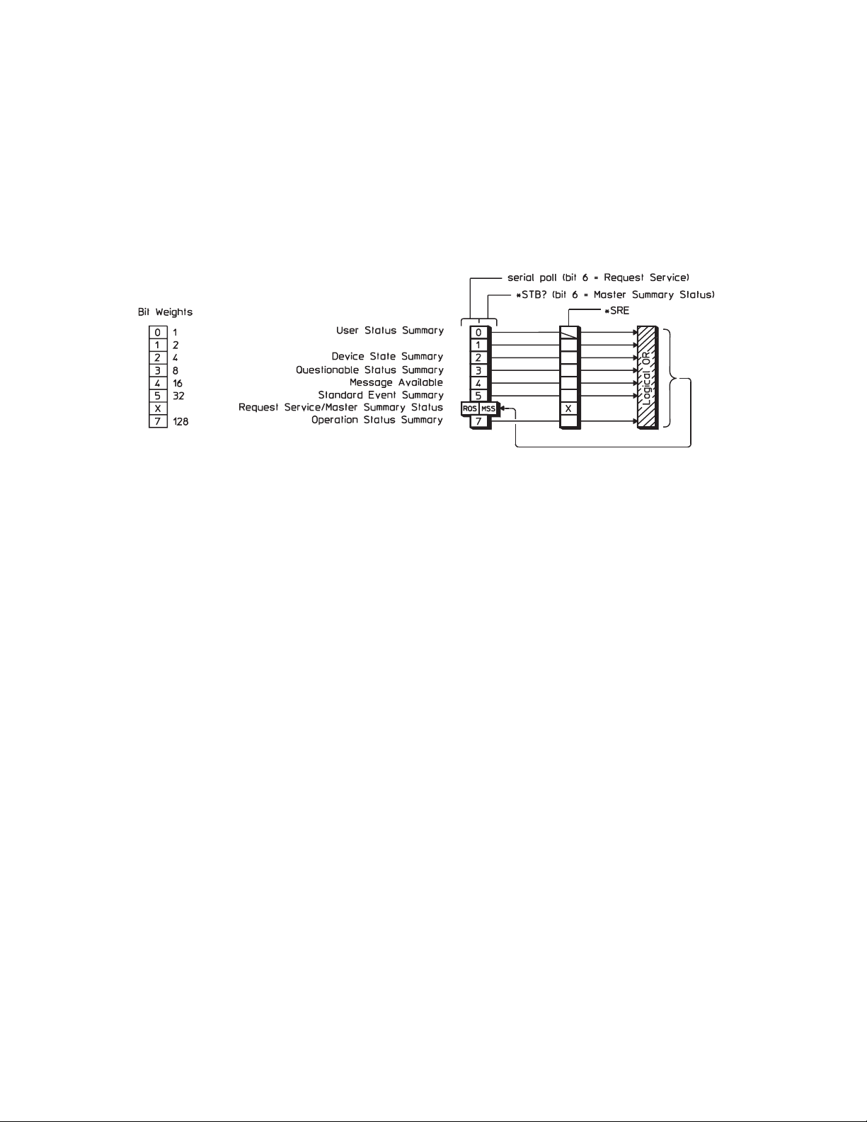
The Status Byte register set summarizes the states of the other register sets and monitors the analyzer’s
output queue. It is also responsible for generating service requests. See figure 1-6.
1-6. The Status Byte Register Set
The Status Byte register set contains only two registers: the Status Byte register and the Service Request
enable register. The Status Byte register behaves like a condition register for all bits except bit 6. The
Service Request enable register behaves like a standard enable register except that bit 6 is always set to 0.
For more information about generating service requests, see “How to Use Registers” in the GPIB
Programmer’s Guide.
1-14
Page 33

The Agilent 35670A’s Status Registers
Bits in the Status Byte register are set to 1 under the following conditions:
User Status Summary (bit 0) is set to 1 when one or more enabled bits in the User Status event
register are set to 1.
Device State Summary (bit 2) is set to 1 when one or more enabled bits in the Device State event
register are set to 1.
Questionable Status Summary (bit 3) is set to 1 when one or more enabled bits in the Questionable
Status event register are set to 1.
Message Available (bit 4) is set to 1 when the output queue contains a response message.
Standard Event Summary (bit 5) is set to 1 when one or more enabled bits in the Standard Event event
register are set to 1.
Master Summary Status (bit 6, when read by *STB) is set to 1 when one or more enabled bits in the
Status Byte register are set to 1.
Request Service (bit 6, when read by serial poll) is set to 1 by the service request process (see “How
to Use Registers” in the
GPIB Programmer’s Guide
).
Operation Status Summary (bit 7) is set to 1 when one or more enabled bits in the Operation Status
event register are set to 1.
Figure 1-6 also shows the commands you use to read and write the Status Byte registers. See chapter 20
for more information about these commands.
1-15
Page 34
The Agilent 35670A’s Status Registers
Device State Register Set
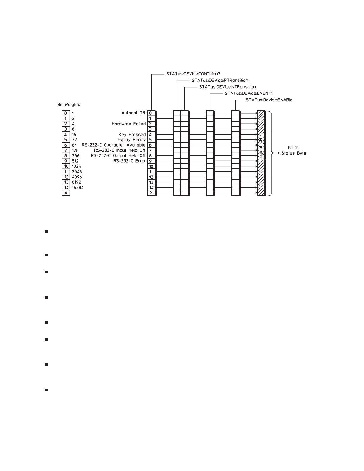
The Device State register set monitors the states of eight device-specific parameters. See figure 1-7.
1-7. The Device State Register Set
Bits in the Device State condition register are set to 1 under the following conditions:
Autocal Off (bit 0) is set to 1 when the analyzer’s autocalibration function is disabled (CAL:AUTO
OFF).
Hardware Failed (bit 2) is set to 1 when the analyzer detects a failure in its own hardware.
Key Pressed (bit 4) is set to 1 when one of the front panel keys is pressed. This is an event. The
condition register will always return 0 for this bit.
Display Ready (bit 5) is set to 1 when measurement results are available. This is an event. The
condition register will always return 0 for this bit.
RS-232-C Character Available (bit 6) is set to 1 when a character is in the input buffer.
RS-232-C Input Held Off (bit 7) is set to 1 when input is held off due to handshake protocol
conditions.
RS-232-C Output Held Off (bit 8) is set to 1 when output is held off due to handshake protocol
conditions.
RS-232-C Error (bit 9) is set to 1 when a framing error, overrun error, parity error, or break is
detected.
Figure 1-7 also shows the commands you use to read and write the Device State registers. See chapter 20
for more information about these commands.
1-16
Page 35
The Agilent 35670A’s Status Registers
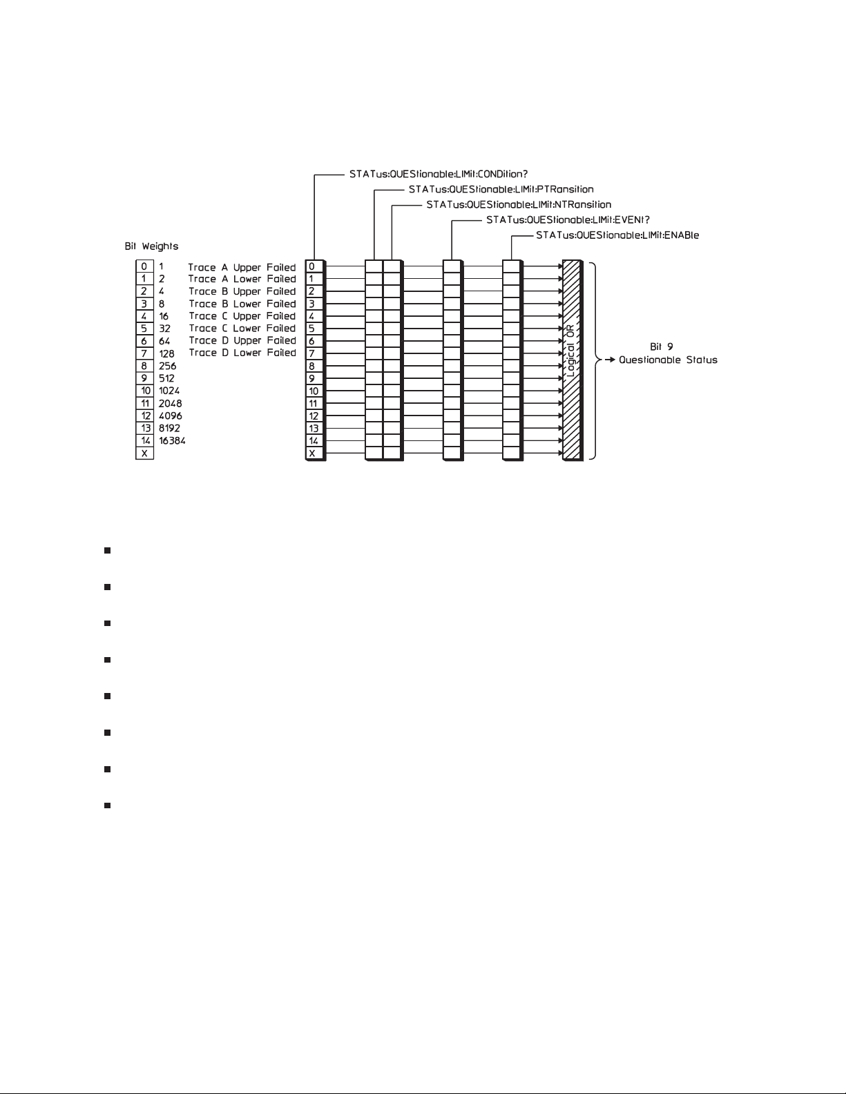
Limit Fail Register Set
The Limit Fail register set monitors limit test results for all traces. See figure 1-8.
1-8. The Limit Fail Register Set
Bits in the Limit Fail condition register are set to 1 under the following conditions:
Trace A Upper Failed (bit 0) is set to 1 when limit testing is enabled and any point on trace A
exceeds its upper limit.
Trace A Lower Failed (bit 1) is set to 1 when limit testing is enabled and any point on trace A falls
below its lower limit.
Trace B Upper Failed (bit 2) is set to 1 when limit testing is enabled and any point on trace B exceeds
its upper limit.
Trace B Lower Failed (bit 3) is set to 1 when limit testing is enabled and any point on trace B falls
below its lower limit.
Trace C Upper Failed (bit 4) is set to 1 when limit testing is enabled and any point on trace C exceeds
its upper limit.
Trace C Lower Failed (bit 5) is set to 1 when limit testing is enabled and any point on trace C falls
below its lower limit.
Trace D Upper Failed (bit 6) is set to 1 when limit testing is enabled and any point on trace D
exceeds its upper limit.
Trace D Lower Failed (bit 7) is set to 1 when limit testing is enabled and any point on trace D falls
below its lower limit.
Figure 1-8 also shows the commands you use to read and write the Limit Fail registers. See chapter 20
for more information about these commands.
1-17
Page 36
The Agilent 35670A’s Status Registers
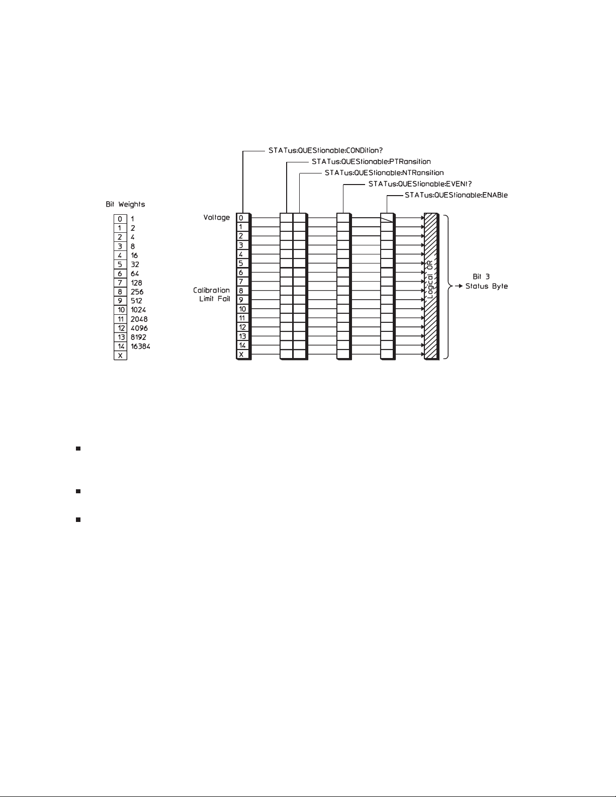
Questionable Status Register Set
The Questionable Status register set monitors conditions that affect the quality of measurement data. See
figure 1-9.
1-9. The Questionable Status Register Set
Bits in the Questionable Status condition register are set to 1 under the following conditions:
Voltage (bit 0) is set to 1 when one or more enabled bits in the Questionable Voltage event register
are set to 1.
Calibration (bit 8) is set to 1 when the last self-calibration attempted by the analyzer failed.
Limit Fail (bit 9) is set to 1 when one or more enabled bits in the Limit Fail event register are set to 1.
Figure 1-9 also shows the commands you use to read and write the Questionable Status registers. See
chapter 20 for more information about these commands.
1-18
Page 37
The Agilent 35670A’s Status Registers
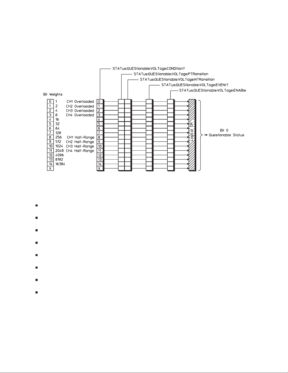
Questionable Voltage Register Set
The Questionable Voltage register set monitors conditions that affect the amplitude accuracy of
measurement data. See figure 1-10.
1-10. The Questionable Voltage Register Set
Bits in the Questionable Voltage condition register are set to 1 under the following conditions:
Channel 1 Overload (bit 0) is set to 1 when any input signal exceeds the current channel 1 input
range.
Channel 2 Overload (bit 1) is set to 1 when any input signal exceeds the current channel 2 input
range.
Channel 3 Overload (bit 2) in Option AY6 only is set to 1 when any input signal exceeds the current
channel 3 input range.
Channel 4 Overload (bit 3) in Option AY6 only is set to 1 when any input signal exceeds the current
channel 4 input range.
Channel 1 Input Half-Range (bit 8) is set to 1 when any input signal is larger than half the current
channel 1 input range.
Channel 2 Input Half-Range (bit 9) is set to 1 when any input signal is larger than half the current
channel 2 input range.
Channel 3 Input Half-Range (bit 10) in Option AY6 only, is set to 1 when any input signal is larger
than half the current channel 3 input range.
Channel 4 Input Half-Range (bit 11) in Option AY6 only, is set to 1 when any input signal is larger
than half the current channel 4 input range.
Figure 1-10 also shows the commands you use to read and write the Questionable Voltage registers. See
chapter 20 for more information about these commands.
1-19
Page 38
The Agilent 35670A’s Status Registers
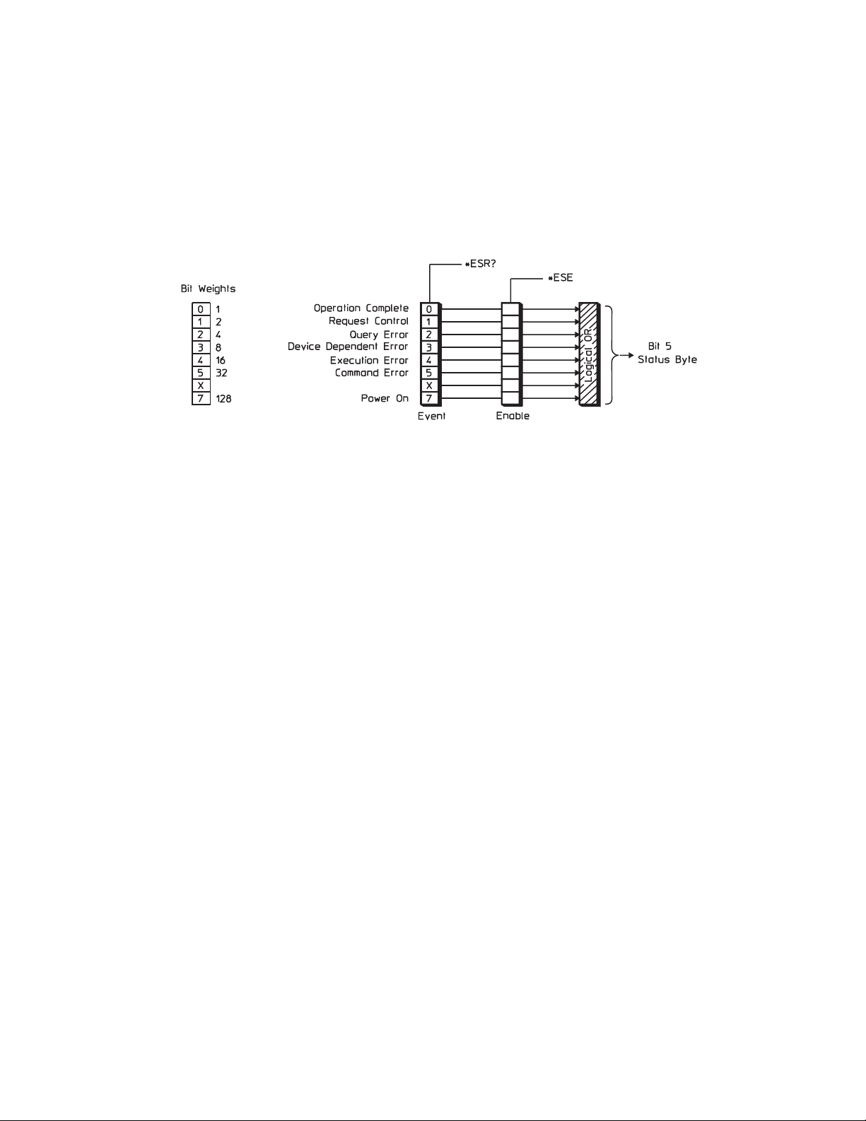
Standard Event Register Set
The Standard Event register set monitors GPIB errors and synchronization conditions. See
figure 1-11.
1-11. The Standard Event Register Set
The Standard Event register set contains only two registers: the Standard Event event register and the
Standard Event enable register. The Standard Event event register is similar to other event registers, but
behaves like a positive transition register with all bits set to 1. The Standard Event enable register is the
same as other enable registers.
For more information about the behavior of the Standard Event register set, see the GPIB Programmer’s
Guide.
1-20
Page 39

The Agilent 35670A’s Status Registers
Bits in the Standard Event event register are set to 1 under the following conditions:
Operation Complete (bit 0) is set to one when the following two events occur (in the order listed):
You send the *OPC command to the analyzer.
–
The analyzer completes all pending overlapped commands (see “Command Synchronization”
–
earlier in this chapter).
Request Control (bit 1) is set to 1 when both of the following conditions are true:
The analyzer is configured as an addressable-only GPIB device (see “Controller Capabilities”
–
earlier in this chapter).
The analyzer is instructed to do something (such as plotting or printing) that requires it to take
–
control of the bus.
Query Error (bit 2) is set to 1 when the command parser detects a query error.
Device Dependent Error (bit 3) is set to 1 when the command parser detects a device-dependent error.
Execution Error (bit 4) is set to 1 when the command parser detects an execution error.
Command Error (bit 5) is set to 1 when the command parser detects a command error.
Power On (bit 7) is set to 1 when you turn on the analyzer.
Figure 1-11 also shows the commands you use to read and write the Standard Event registers. See
chapter 20 for more information about these commands.
1-21
Page 40
The Agilent 35670A’s Status Registers
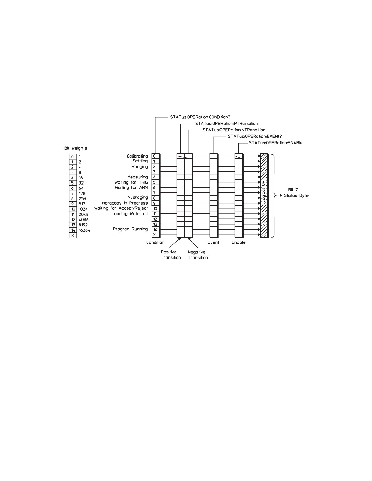
Operation Status Register Set
The Operation Status register set monitors conditions in the analyzer’s measurement process, disk
operations, and printing/plotting operations. It also monitors the state of current Instrument BASIC
program. See figure 1-12.
1-12. The Operation Status Register Set
1-22
Page 41

The Agilent 35670A’s Status Registers
Bits in the Operation Status condition register are set to 1 under the following conditions:
Calibrating (bit 0) is set to 1 while the self-calibration routine is running.
Settling (bit 1) is set to 1 while the measurement hardware is settling.
Ranging (bit 2) is set to 1 while the input range is changing.
Measuring (bit 4) is set to 1 while the analyzer is collecting data for a measurement.
Waiting for TRIG (bit 5) is set to 1 when the analyzer is ready to accept a trigger signal from one of
the trigger sources. (If a trigger signal is sent before this bit is set, the signal is ignored.)
Waiting for ARM (bit 6) is set to 1 when both of the following conditions are true:
Manual arming is selected.
–
The analyzer is ready to be armed.
–
(If you send the ARM:IMM command before this bit is set, the command is ignored.)
Averaging (bit 8) is set to 1 while the analyzer is averaging measurement data. If averaging is
disabled ([SENSe:]AVERage[:STATe] OFF) this bit is set to 1 whenever the Measuring bit (bit 4) is
set to 1 during data collection.
Hardcopy In Progress (bit 9) is set to 1 while the analyzer is performing a print or plot operation.
Waiting for Accept/Reject (bit 10) is set to 1 while the analyzer is waiting for a response during
preview averaging ([SENSe:]AVERage:PREView MANual).
Loading Waterfall (bit 11) is set to 1 while the analyzer is collecting the specified number of traces
for a waterfall display.
Program Running (bit 14) is set to 1 while the current Instrument BASIC program is running.
Figure 18-1 under the [SENSe:]AVERage[:STATe] command illustrates the transition of the bits in the
Operation Status condition register.
Figure 1-12 also shows the commands you use to read and write the Operation Status registers. See
chapter 20 for more information about these commands.
1-23
Page 42
The Agilent 35670A’s Status Registers
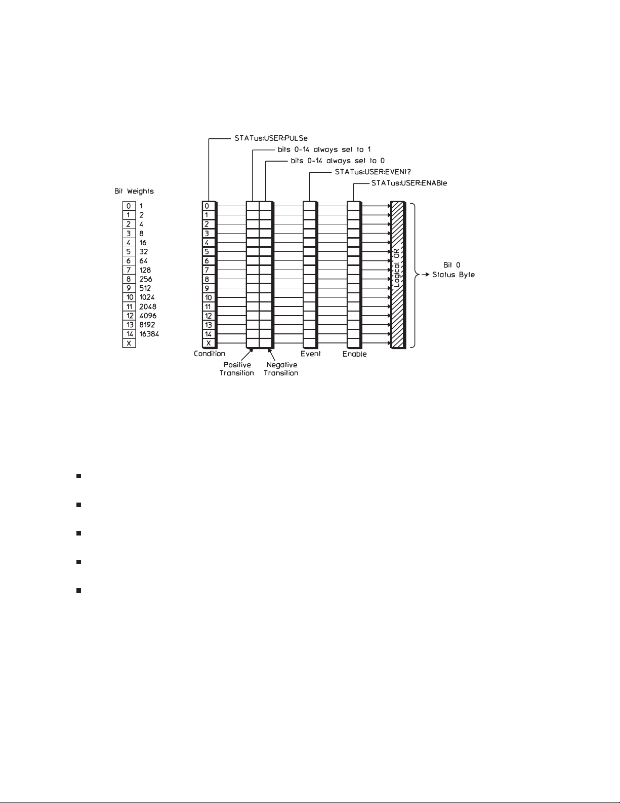
User Status Register Set
The User Status register set detects STATus:USER:PULSe commands. See figure 1-13.
1-13. The User Status Register Set
The User Status register set conforms to the general status register model (described at the beginning of
this chapter) with the following exceptions:
You can write (but not read) the condition register.
You cannot write or read the transition registers.
Bits in the positive transition register are always set to 1.
Bits in the negative transition register are always set to 0.
Bit 15 is not available. It is always set to 0.
Bits in the User Status condition register are normally set to 0, but are set to 1 (briefly) when you send a
STAT:USER:PULS command. If you send STAT:USER:PULS 32, bit 5 of the condition register is
pulsed high (2
5
= 32).
Figure 1-13 also shows the commands you use to read or write the User Status registers. See chapter 20
for more information about these commands.
1-24
Page 43
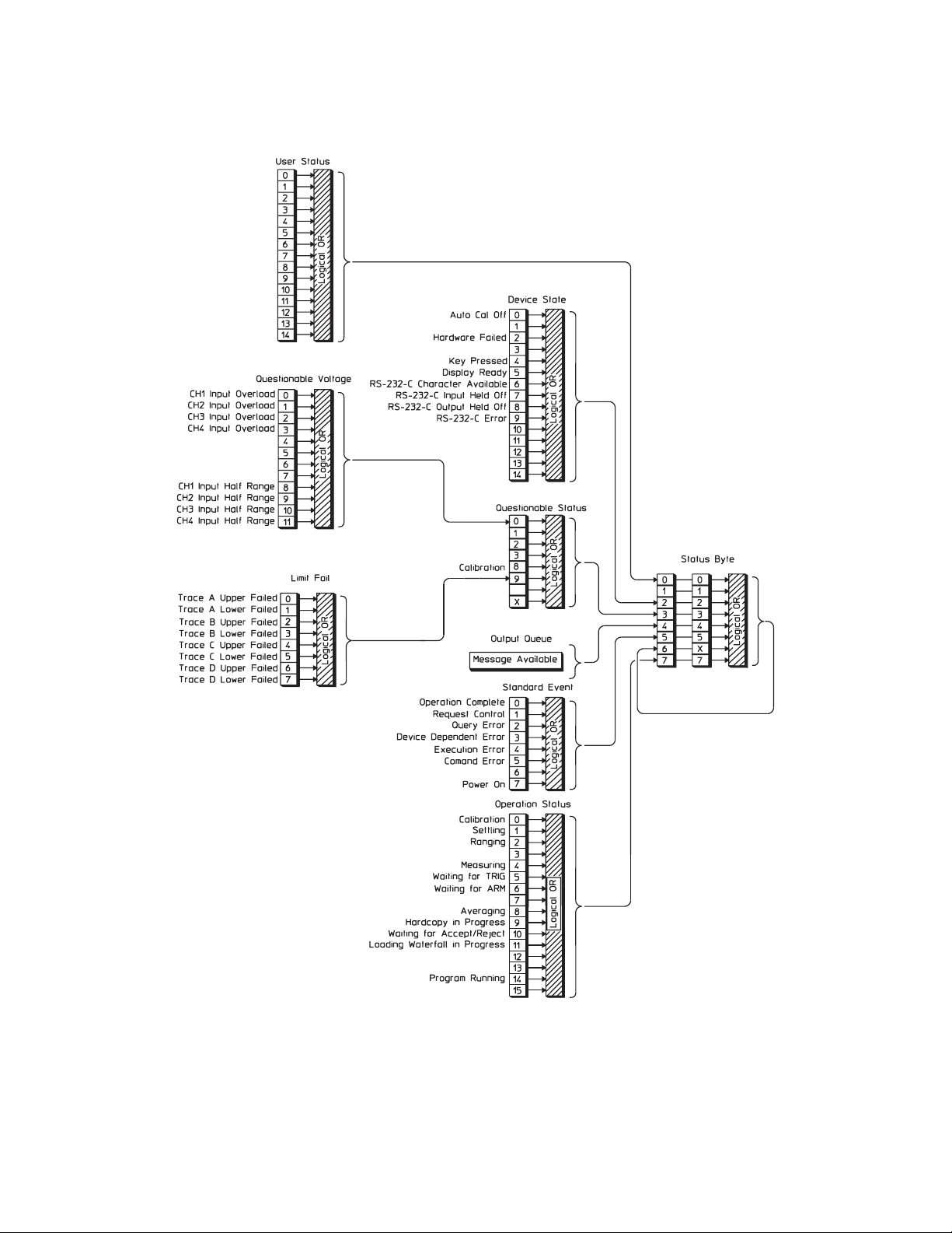
Agilent 35670A Register Set Summary
The Agilent 35670A’s Status Registers
Figure 1-14. Agilent35670A Register Set Summary
1-25
Page 44

SCPI Compliance Information
SCPI Compliance Information
Many of the Agilent 35670A’s GPIB commands comply to SCPI. The attribute summary in the
command reference section identifies these commands as follows:
Confirmed commands which comply to SCPI 1992.
Approved commands which will be added to SCPI 1993.
Instrument-specific commands which do not comply to SCPI.
Use the SYSTem:VERSion? query to determine the SCPI version to which your analyzer complies.
To enter the query in BASIC, you simply type
OUTPUT @711;"SYSTEM:VERSION?"
ENTER @711;version
The analyzer returns a value that looks like this:
1992.0
where 1992 is the year-version and 0 is the revision number for that year.
1-26
Page 45

Confirmed Commands
*CAL?
*CLS
*ESE
*ESR?
*IDN?
*OPC
*OPT?
*PCB-?
*PSC
*RST
*SRE
*STB?
*TRG
ABORt
ARM[:IMMediate]
ARM:SOURce
SCPI Compliance Information
CALCulate[1|2]:DATA?
CALCulate[1|2]:FEED
CALCulate[1|2]:FORMat
CALCulate[1|2]:LIMit:FAIL?
CALCulate[1|2]:LIMit:STATe
CALCulate[1|2]:MATH:STATe
CALCulate[1|2]:MATH[:EXPRession[1|2|3|4|5]]
CALCulate[1|2]:UNIT:ANGLe
CALibration[:ALL]?
CALibration:AUTO
DISPlay:ANNotation[:ALL]
DISPlay:CONTents
DISPlay:ENABle
DISPlay:FORMat
DISPlay:PROGram[:MODE]
DISPlay[:WINDow[1|2]]:TRACe:GRATicule:GRID[:STATe]
DISPlay[:WINDow[1|2]]:TRACe:X:SPACing
DISPlay[:WINDow[1|2]]:TRACe:X[:SCALe]:LEFT
DISPlay[:WINDow[1|2]]:TRACe:X[:SCALe]:RIGHt
DISPlay[:WINDow[1|2]]:TRACe:Y[:SCALe]:AUTO
DISPlay[:WINDow[1|2]]:TRACe:Y[:SCALe]:BOTTom
DISPlay[:WINDow[1|2]]:TRACe:Y[:SCALe]:PDIVision
DISPlay[:WINDow[1|2]]:TRACe:Y[:SCALe]:TOP
DISPlay[:WINDow[1|2]]:TRACe:Y:SPACing
1-27
Page 46

SCPI Compliance Information
FORMat[:DATA]
INITiate:CONTinuous
INITiate[:IMMediate]
INPut[1|2]:BIAS[:STATe]
INPut[1|2]:COUPling
INPut[1|2]:FILTer:AWEighting[:STATe]
INPut[1|2]:FILTer[:LPASs][:STATe]
INPut[1|2]:LOW
INPut[1|2][:STATe]
INSTrument:NSELect
INSTrument[:SELect]
MEMory:CATalog[:ALL]?
MEMory:DELete:ALL
MEMory:DELete[:NAME]-?
MEMory:FREE[:ALL]?
MMEMory:COPY-?
MMEMory:DELete-?
MMEMory:INITialize-?
MMEMory:LOAD:STATe-?
MMEMory:LOAD:TRACe-?
MMEMory:MOVE-?
MMEMory:MSIS
MMEMory:STORe:STATe-?
MMEMory:STORe:TRACe-?
OUTPut[:STATe]
PROGram:EXPLicit:DEFine
PROGram[:SELected]:DEFine
PROGram[:SELected]:DELete:ALL
PROGram[:SELected]:DELete[:SELected]
PROGram[:SELected]:MALLocate
PROGram[:SELected]:NAME
PROGram[:SELected]:NUMBer
PROGram[:SELected]:STATe
PROGram[:SELected]:STRing
1-28
Page 47

SOURce:FREQuency[:CW]
SOURce:FREQuency:FIXed
SOURce:FUNCtion[:SHAPe]
SOURce:VOLTage:LIMit[:AMPLitude]
SOURce:VOLTage[:LEVel][:IMMediate][:AMPLitude]
SOURce:VOLTage:SLEW
[SENSe:]AVERage:COUNt
[SENSe:]AVERage:TCONtrol
[SENSe:]AVERage:TYPE
[SENSe:]AVERage[:STATe]
[SENSe:]FREQuency:CENTer
[SENSe:]FREQuency:MANual
[SENSe:]FREQuency:RESolution
[SENSe:]FREQuency:RESolution:AUTO
[SENSe:]FREQuency:SPAN
[SENSe:]FREQuency:SPAN:FULL
[SENSe:]FREQuency:SPAN:LINK
[SENSe:]FREQuency:STARt
[SENSe:]FREQuency:STEP[:INCRement]
[SENSe:]FREQuency:STOP
[SENSe:]SWEep:DIRection
[SENSe:]SWEep:DWELl
[SENSe:]SWEep:MODE
[SENSe:]SWEep:SPACing
[SENSe:]SWEep:TIME
[SENSe:]VOLTage[1|2]:RANGe:AUTO
[SENSe:]VOLTage[1|2]:RANGe[:UPPer]
[SENSe:]WINDow[1|2]:EXPonential
[SENSe:]WINDow[1|2]:FORCe
[SENSe:]WINDow[1|2][:TYPE]
SCPI Compliance Information
STATus:OPERation:CONDition?
STATus:OPERation:ENABle
STATus:OPERation:NTRansition
STATus:OPERation:PTRansition
STATus:OPERation[:EVENt]?
STATus:PRESet
STATus:QUEStionable:CONDition?
STATus:QUEStionable:ENABle
STATus:QUEStionable:NTRansition
STATus:QUEStionable:PTRansition
STATus:QUEStionable:VOLTage:CONDition?
STATus:QUEStionable:VOLTage:ENABle
STATus:QUEStionable:VOLTage:NTRansition
STATus:QUEStionable:VOLTage:PTRansition
STATus:QUEStionable:VOLTage[:EVENt]?
1-29
Page 48

SCPI Compliance Information
SYSTem:BEEPer:STATe
SYSTem:BEEPer[:IMMediate]-?
SYSTem:COMMunicate:GPIB:ADDRess
SYSTem:COMMunicate:SERial[:RECeive]:BAUD
SYSTem:COMMunicate:SERial[:RECeive]:BITS
SYSTem:COMMunicate:SERial[:RECeive]:PACE
SYSTem:COMMunicate:SERial[:RECeive]:PARity:CHECk
SYSTem:COMMunicate:SERial[:RECeive]:PARity[:TYPE]
SYSTem:COMMunicate:SERial[:RECeive]:SBITs
SYSTem:COMMunicate:SERial:TRANsmit:PACE
SYSTem:DATE
SYSTem:ERRor?
SYSTem:KEY
SYSTem:KLOCk
SYSTem:PRESet
SYSTem:SET
SYSTem:TIME
SYSTem:VERSion?
TRACe[:DATA]
TRACe:WATerfall[:DATA]
TRIGger[:IMMediate]
TRIGger:LEVel
TRIGger:SLOPe
TRIGger:SOURce
1-30
Page 49

List of Approved Commands
HCOPy:DESTination
HCOPy:DEVice:LANGuage (except PHPGl
HCOPy:DEVice:SPEed
HCOPy[:IMMediate]
HCOPy:ITEM:ALL[:IMMediate]
HCOPy:ITEM:FFEed:STATe
HCOPy:ITEM:LABel:STATe
HCOPy:ITEM:LABel:TEXT
HCOPy:ITEM:TDSTamp:STATe
HCOPy:ITEM[:WINDow[1|2|3|4]]:TRACe:COLor
HCOPy:ITEM[:WINDow[1|2|3|4]]:TRACe:GRATicule:COLor
HCOPy:ITEM[:WINDow[1|2|3|4]]:TRACe:GRATicule[:IMMediate]
HCOPy:ITEM[:WINDow[1|2|3|4]]:TRACe[:IMMediate]
HCOPy:ITEM[:WINDow[1|2|3|4]]:TRACe:LTYPe
HCOPy:PAGE:DIMensions:AUTO
MMEMory:NAME
SCPI Compliance Information
1-31
Page 50

SCPI Compliance Information
List of Instrument Specific Commands
ARM:RPM:INCRement
ARM:RPM:MODE
ARM:RPM:THReshold
ARM:TIMer
CALCulate[1|2|3|4]:CFIT:ABORt
CALCulate[1|2|3|4]:CFIT:COPY
CALCulate[1|2|3|4]:CFIT:DATA
CALCulate[1|2|3|4]:CFIT:DESTination
CALCulate[1|2|3|4]:CFIT:FREQuency[:AUTO]
CALCulate[1|2|3|4]:CFIT:FREQuency:STARt
CALCulate[1|2|3|4]:CFIT:FREQuency:STOP
CALCulate[1|2|3|4]:CFIT:FSCale
CALCulate[1|2|3|4]:CFIT[:IMMediate]
CALCulate[1|2|3|4]:CFIT:ORDer:AUTO
CALCulate[1|2|3|4]:CFIT:ORDer:POLes
CALCulate[1|2|3|4]:CFIT:ORDer:ZERos
CALCulate[1|2|3|4]:CFIT:TDELay
CALCulate[1|2|3|4]:CFIT:WEIGht:AUTO
CALCulate[1|2|3|4]:CFIT:WEIGht:REGister
CALCulate[1|2|3|4]:DATA:HEADer:POINts
CALCulate[1|2|3|4]:GDAPerture:APERture
CALCulate[1|2|3|4]:LIMit:BEEP[:STATe]
CALCulate[1|2|3|4]:LIMit:LOWer:CLEar[:IMMediate]
CALCulate[1|2|3|4]:LIMit:LOWer:MOVE:Y
CALCulate[1|2|3|4]:LIMit:LOWer:REPort[:DATA]
CALCulate[1|2|3|4]:LIMit:LOWer:REPort:YDATa
CALCulate[1|2|3|4]:LIMit:LOWer:SEGMent
CALCulate[1|2|3|4]:LIMit:LOWer:SEGMent:CLEar
CALCulate[1|2|3|4]:LIMit:LOWer:TRACe[:IMMediate]
CALCulate[1|2|3|4]:LIMit:UPPer:CLEar[:IMMediate]
CALCulate[1|2|3|4]:LIMit:UPPer:MOVE:Y
CALCulate[1|2|3|4]:LIMit:UPPer:REPort[:DATA]
CALCulate[1|2|3|4]:LIMit:UPPer:REPort:YDATa
CALCulate[1|2|3|4]:LIMit:UPPer:SEGMent
CALCulate[1|2|3|4]:LIMit:UPPer:SEGMent:CLEar
CALCulate[1|2|3|4]:LIMit:UPPer:TRACe[:IMMediate]
CALCulate[1|2|3|4]:MARKer:BAND:STARt
CALCulate[1|2|3|4]:MARKer:BAND:STOP
CALCulate[1|2|3|4]:MARKer:COUPled[:STATe]
CALCulate[1|2|3|4]:MARKer:DTABle:CLEar[:IMMediate]
CALCulate[1|2|3|4]:MARKer:DTABle:COPY[1|2|3|4]
CALCulate[1|2|3|4]:MARKer:DTABle[:DATA]
CALCulate[1|2|3|4]:MARKer:DTABle:X[:DATA]
CALCulate[1|2|3|4]:MARKer:DTABle:X:DELete
CALCulate[1|2|3|4]:MARKer:DTABle:X:INSert
1-32
Page 51

CALCulate[1|2|3|4]:MARKer:DTABle:X:LABel
CALCulate[1|2|3|4]:MARKer:DTABle:X:SELect[:POINt]
CALCulate[1|2|3|4]:MARKer:FUNCtion
CALCulate[1|2|3|4]:MARKer:FUNCtion:RESult
CALCulate[1|2|3|4]:MARKer:HARMonic:COUNt
CALCulate[1|2|3|4]:MARKer:HARMonic:FUNDamental
CALCulate[1|2|3|4]:MARKer:MAXimum[:GLOBal]
CALCulate[1|2|3|4]:MARKer:MAXimum[:GLOBal]:TRACk
CALCulate[1|2|3|4]:MARKer:MAXimum:LEFT
CALCulate[1|2|3|4]:MARKer:MAXimum:RIGHt
CALCulate[1|2|3|4]:MARKer:MODE
CALCulate[1|2|3|4]:MARKer:POSition
CALCulate[1|2|3|4]:MARKer:POSition:POINt
CALCulate[1|2|3|4]:MARKer:REFerence:X
CALCulate[1|2|3|4]:MARKer:REFerence:Y
CALCulate[1|2|3|4]:MARKer:SIDeband:CARRier
CALCulate[1|2|3|4]:MARKer:SIDeband:COUNt
CALCulate[1|2|3|4]:MARKer:SIDeband:INCRement
CALCulate[1|2|3|4]:MARKer[:STATe]
CALCulate[1|2|3|4]:MARKer:X[:ABSolute]
CALCulate[1|2|3|4]:MARKer:X:RELative
CALCulate[1|2|3|4]:MARKer:Y[:ABSolute]
CALCulate[1|2|3|4]:MARKer:Y:RELative
CALCulate[1|2|3|4]:MATH:CONStant[1|2|3|4|5]
CALCulate[1|2|3|4]:MATH:DATA
CALCulate[1|2|3|4]:MATH:SELect
CALCulate[1|2|3|4]:SYNThesis:COPY
CALCulate[1|2|3|4]:SYNThesis:DATA
CALCulate[1|2|3|4]:SYNThesis:DESTination
CALCulate[1|2|3|4]:SYNThesis:FSCale
CALCulate[1|2|3|4]:SYNThesis:GAIN
CALCulate[1|2|3|4]:SYNThesis[:IMMediate]
CALCulate[1|2|3|4]:SYNThesis:SPACing
CALCulate[1|2|3|4]:SYNThesis:TDELay
CALCulate[1|2|3|4]:SYNThesis:TTYPe
CALCulate[1|2|3|4]:UNIT:AMPLitude
CALCulate[1|2|3|4]:UNIT:DBReference
CALCulate[1|2|3|4]:UNIT:DBReference:IMPedance
CALCulate[1|2|3|4]:UNIT:DBReference:USER:LABel
CALCulate[1|2|3|4]:UNIT:DBReference:USER:REFerence
CALCulate[1|2|3|4]:UNIT:MECHanical
CALCulate[1|2|3|4]:UNIT:VOLTage
CALCulate[1|2|3|4]:UNIT:X
CALCulate[1|2|3|4]:UNIT:X:ORDer:FACTor
CALCulate[1|2|3|4]:UNIT:X:USER:FREQuency:FACTor
CALCulate[1|2|3|4]:UNIT:X:USER:FREQuency:LABel
CALCulate[1|2|3|4]:UNIT:X:USER:TIME:FACTor
CALCulate[1|2|3|4]:UNIT:X:USER:TIME:LABel
CALCulate[1|2|3|4]:WATerfall:COUNt
CALCulate[1|2|3|4]:WATerfall[:DATA]
SCPI Compliance Information
1-33
Page 52

SCPI Compliance Information
CALCulate[1|2|3|4]:WATerfall:SLICe:COPY
CALCulate[1|2|3|4]:WATerfall:SLICe:SELect
CALCulate[1|2|3|4]:WATerfall:SLICe:SELect:POINt
CALCulate[1|2|3|4]:WATerfall:TRACe:COPY
ALCulate[1|2|3|4]:WATerfall:TRACe:SELect
CALCulate[1|2|3|4]:WATerfall:TRACe:SELect:POINt
DISPlay:BODE
DISPlay:BRIGhtness
DISPlay:ERRor
DISPlay:EXTernal[:STATe]
DISPlay:GPIB:ECHO
DISPlay:PROGram:KEY:BOX
DISPlay:PROGram:KEY:BRACket
DISPlay:PROGram:VECTor:BUFFer[:STATe]
DISPlay:RPM[:STATe]
DISPlay:STATe
DISPlay:TCAPture:ENVelope[:STATe]
DISPlay:VIEW
DISPlay[:WINDow[1|2|3|4]]:DTABle:MARKer[:STATe]
DISPlay[:WINDow[1|2|3|4]]:DTABle[:STATe]
DISPlay[:WINDow[1|2|3|4]]:LIMit:STATe
DISPlay[:WINDow[1|2|3|4]]:POLar:CLOCkwise
DISPlay[:WINDow[1|2|3|4]]:POLar:ROTation
DISPlay[:WINDow[1|2|3|4]]:TRACe:APOWer[:STATe]
DISPlay[:WINDow[1|2|3|4]]:TRACe:BPOWer[:STATe]
DISPlay[:WINDow[1|2|3|4]]:TRACe:LABel
DISPlay[:WINDow[1|2|3|4]]:TRACe:LABel:DEFault[:STATe]
DISPlay[:WINDow[1|2|3|4]]:TRACe:X:MATCh[1|2|3|4]
DISPlay[:WINDow[1|2|3|4]]:TRACe:X[:SCALe]:AUTO
DISPlay[:WINDow[1|2|3|4]]:TRACe:Y:MATCh[1|2|3|4]
DISPlay[:WINDow[1|2|3|4]]:TRACe:Y[:SCALe]:CENTer
DISPlay[:WINDow[1|2|3|4]]:TRACe:Y[:SCALe]:REFerence
DISPlay[:WINDow[1|2|3|4]]:WATerfall:BASeline
DISPlay[:WINDow[1|2|3|4]]:WATerfall:BOTTom
DISPlay[:WINDow[1|2|3|4]]:WATerfall:COUNt
DISPlay[:WINDow[1|2|3|4]]:WATerfall:HEIGht
DISPlay[:WINDow[1|2|3|4]]:WATerfall:HIDDen
DISPlay[:WINDow[1|2|3|4]]:WATerfall:SKEW
DISPlay[:WINDow[1|2|3|4]]:WATerfall:SKEW:ANGLe
DISPlay[:WINDow[1|2|3|4]]:WATerfall[:STATe]
DISPlay[:WINDow[1|2|3|4]]:WATerfall:TOP
HCOPy::COLor:DEFault
HCOPy:ITEM:LABel:COLor 0~16
HCOPy:ITEM:TDSTamp:FORMat
HCOPy:ITEM[:WINDow[1|2|3|4]]:TRACe:LIMit:LTYPe
HCOPy:ITEM[:WINDow[1|2|3|4]]:TRACe:MARKer:COLor
1-34
Page 53

HCOPy:ITEM[:WINDow[1|2|3|4]]:TRACe:MARKer[:IMMediate]
HCOPy:ITEM[:WINDow[1|2|3|4]]:TRACe:MARKer:REFerence[:IMMediate]
HCOPy:PAGE:DIMensions:USER:LLEFt
HCOPy:PAGE:DIMensions:USER:URIGht
HCOPy:PLOT:ADDRess
HCOPy:PRINt:ADDRess
HCOPy:TITLe[1|2]
INPut[1|2|3|4]:REFerence:DIRection 0~32767
INPut[1|2|3|4]:REFerence:POINt 0~32767
MEMory:CATalog:NAME?
MMEMory:DISK:ADDRess
MMEMory:DISK:UNIT
MMEMory:FSYStem?
MMEMory:LOAD:CFIT
MMEMory:LOAD:CONTinue
MMEMory:LOAD:CONTinue?
MMEMory:LOAD:DTABle:TRACe[1|2|3|4]
MMEMory:LOAD:LIMit:LOWer:TRACe[1|2|3|4
MMEMory:LOAD:LIMit:UPPer:TRACe[1|2|3|4]
MMEMory:LOAD:MATH
MMEMory:LOAD:PROGram
MMEMory:LOAD:SYNThesis
MMEMory:LOAD:TCAPture
MMEMory:LOAD:WATerfall
MMEMory:MDIRectory
MMEMory:STORe:CFIT
MMEMory:STORe:CONTinue
MMEMory:STORe:CONTinue?
MMEMory:STORe:DTABle:TRACe[1|2|3|4]
MMEMory:STORe:LIMit:LOWer:TRACe[1|2|3|4]
MMEMory:STORe:LIMit:UPPer:TRACe[1|2|3|4]
MMEMory:STORe:MATH
MMEMory:STORe:PROGram
MMEMory:STORe:PROGram:FORMat
MMEMory:STORe:SYNThesis
MMEMory:STORe:TCAPture
MMEMory:STORe:WATerfall
SCPI Compliance Information
OUTPut:FILTer[:LPASs][:STATe]
PROGram:EDIT:ENABle
PROGram:EXPLicit:LABel
1-35
Page 54

SCPI Compliance Information
PROGram[:SELected]:LABel
[SENSe:]AVERage:CONFidence
[SENSe:]AVERage:HOLD
[SENSe:]AVERage:IMPulse
[SENSe:]AVERage:IRESult:RATE
[SENSe:]AVERage:IRESult[:STATe]
[SENSe:]AVERage:PREView
[SENSe:]AVERage:PREView:ACCept
[SENSe:]AVERage:PREView:REJect
[SENSe:]AVERage:PREView:TIME
[SENSe:]AVERage:TIME
[SENSe:]AVERage:TYPE
[SENSe:]FEED
[SENSe:]FREQuency:BLOCksize
[SENSe:]FREQuency:RESolution:AUTO:MCHange
[SENSe:]FREQuency:RESolution:AUTO:MINimum
[SENSe:]FREQuency:RESolution:OCTave
[SENSe:]HISTogram:BINS
[SENSe:]ORDer:MAXimum
[SENSe:]ORDer:RESolution
[SENSe:]ORDer:RESolution:TRACk
[SENSe:]ORDer:RPM:MAXimum
[SENSe:]ORDer:RPM:MINimum
[SENSe:]ORDer:TRACk[1|2|3|4|5]
[SENSe:]ORDer:TRACk[1|2|3|4|5]:STATe
[SENSe:]REFerence
[SENSe:]REJect:STATe
[SENSe:]SWEep:OVERlap
[SENSe:]SWEep:STIMe
[SENSe:]TCAPture:ABORt
[SENSe:]TCAPture:DELete
[SENSe:]TCAPture[:IMMediate]
[SENSe:]TCAPture:LENGth
[SENSe:]TCAPture:MALLocate
[SENSe:]TCAPture:STARt[1|2|3|4]
[SENSe:]TCAPture:STOP[1|2|3|4]
[SENSe:]TCAPture:TACHometer:RPM:MAXimum
[SENSe:]TCAPture:TACHometer[:STATe]
[SENSe:]VOLTage[1|2|3|4][:DC]:RANGe:AUTO:DIRection
[SENSe:]VOLTage[1|2|3|4][:DC]:RANGe:UNIT:USER:LABel
[SENSe:]VOLTage[1|2|3|4][:DC]:RANGe:UNIT:USER:SFACtor
[SENSe:]VOLTage[1|2|3|4][:DC]:RANGe:UNIT:USER[:STATe]
[SENSe:]VOLTage[1|2|3|4][:DC]:RANGe:UNIT:XDCR:LABel
[SENSe:]WINDow[1|2|3|4]:ORDer:DC
1-36
Page 55

SOURce:BURSt
SOURce:USER:CAPTure
SOURce:USER[:REGister]
SOURce:USER:REPeat
SOURce:VOLTage[:LEVel]:AUTO
SOURce:VOLTage[:LEVel][:IMMediate]:OFFSet
SOURce:VOLTage[:LEVel]:REFerence
SOURce:VOLTage[:LEVel]:REFerence:CHANnel
SOURce:VOLTage[:LEVel]:REFerence:TOLerance
SOURce:VOLTage:LIMit:INPut
STATus:QUEStionable:LIMit:CONDition
STATus:QUEStionable:LIMit:ENABle
STATus:QUEStionable:LIMit[:EVENt]
STATus:QUEStionable:LIMit:NTRansition
STATus:QUEStionable:LIMit:PTRansition
STATus:USER:ENABle
STATus:USER[:EVENt]
STATus:USER:PULSe
SYSTem:FAN[:STATe]
SYSTem:POWer:SOURce
STATus:DEVice:CONDition?
STATus:DEVice:ENABle
STATus:DEVice[:EVENt]
STATus:DEVice:NTRansition
STATus:DEVice:PTRansition
SCPI Compliance Information
TEST:LOG:CLEar
TEST:LONG
TEST:LONG:RESult
TRACe:X[:DATA]?
TRACe:X:UNIT?
TRACe:Z[:DATA]?
TRACe:Z:UNIT?
TRIGger:EXTernal:FILTer[:LPAS][:STATe]
TRIGger:EXTernal:LEVel
TRIGger:EXTernal:RANGe
TRIGger:LEVel:TTL
TRIGger:STARt[1|2|3|4]
TRIGger:TACHometer:HOLDoff
TRIGger:TACHometer:LEVel
TRIGger:TACHometer:PCOunt
TRIGger:TACHometer:RANGe
1-37
Page 56

SCPI Compliance Information
TRIGger:TACHometer[:RPM]
TRIGger:TACHometer:SLOPe
1-38
Page 57

Introduction to the Command Reference
2
Page 58

Page 59
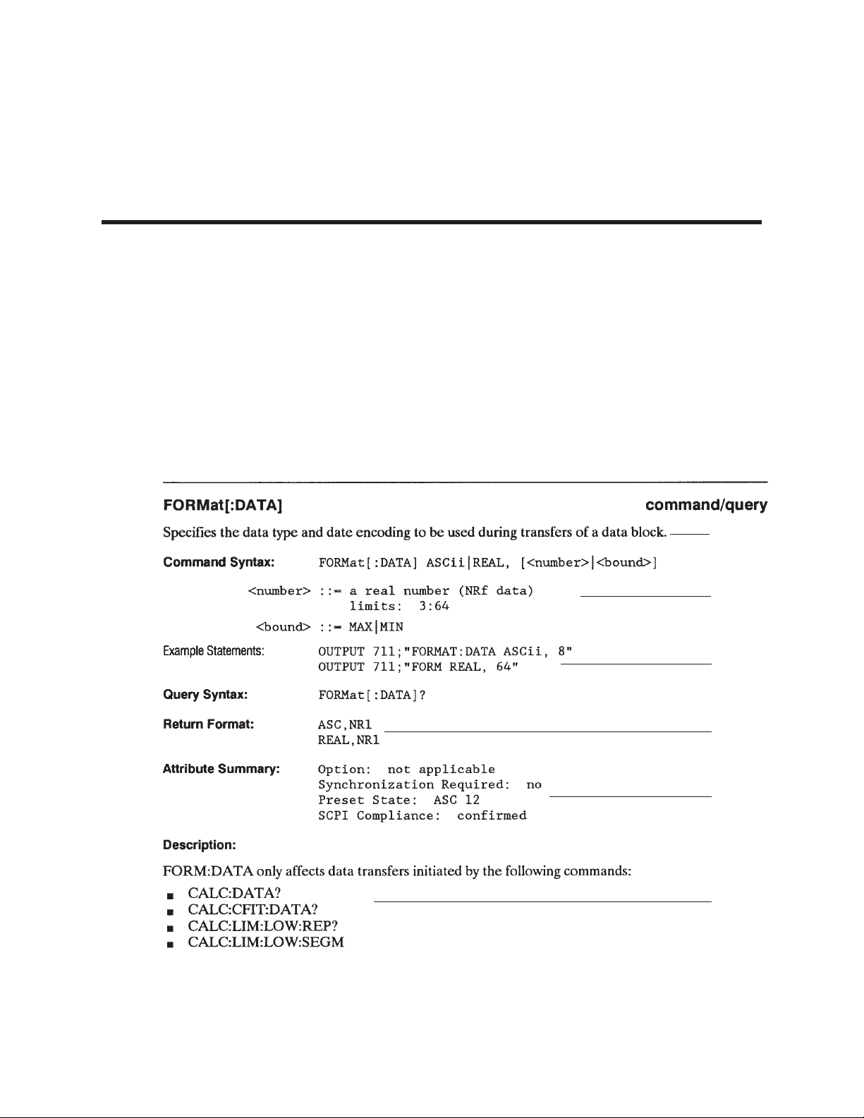
Introduction to the Command Reference
The Command Reference chapters describe all of the Agilent 35670A’s GPIB commands. Each
command has the following:
A brief description of the command. This one- or two-line description appears just below the
heading.
A syntax description. This consists of two fields. One field specifies whether the command has
only a command form, only a query form, or both. The other field shows you the syntax expected
by the analyzer’s GPIB command parser. At the end of this chapter is a detailed description for the
elements appearing in the syntax description. Additional information about message syntax is also
available in the GPIB Programmer’s Guide.
2
1
2
3
4
5
6
2-1. Sample Command Reference Page
2-1
Page 60

Example statements. This field appears at the end of the syntax description. It contains two BASIC
output statements that use the command.
A return format description. This field is only used if the command has a query form. It tells you
how data is returned in response to the query.
An attribute summary. This field indicates whether one of the analyzer’s options must be installed;
identifies overlapped commands requiring synchronization; defines the command’s preset state and
specifies compliance with SCPI. A “confirmed” command complies with SCPI 1992. An
“approved” command complies with SCPI 1993. An “instrument-specific” command does not
conform to the SCPI standard.
A detailed description. This field contains additional information about the command.
2-2
Page 61

Finding the Right Command
Finding the Right Command
If you can not find a command you have seen in a program, remember that commands can omit
implied mnemonics.
For example, the command SENSe:FREQuency:CENTer 10000 HZ contains the implied mnemonic
SENSe. SENSe can be omitted to create the equivalent command FREQuency:CENTer 10000 HZ.
(See “Implied Mnemonics” in the GPIB Programmer’s Guide.) You will not find an entry for
FREQuency:CENTer—or any other command that omits an implied mnemonic—in the Command
Reference. You will find the FREQuency:CENTer command in the SENSe chapter.
If you do not find a command where you expect it, try scanning the command list in appendix A for
the equivalent command that contains the implied mnemonic.
Each command has a brief description. After you locate the equivalent command, you can find a
more detailed description in the corresponding command reference chapter.
If you are looking for a command that accesses a particular function, use the index.
For example, if you want to find the command that changes the analyzer’s center frequency, look
for “center frequency” in the index. It sends you to the page that describes the
SENSe:FREQuency:CENTer command.
If you are familiar with front panel operation of the analyzer, use Appendix B.
It provides a cross reference of the analyzer’s hardkeys and softkeys and their equivalent GPIB
commands.
If you have an analyzer, use the GPIB Echo facility.
GPIB Echo displays the corresponding GPIB command for front panel operations. It displays the
most abbreviated form of the command. To turn on the facility, press
[ Local/GPIB ] [ GPIB ECHO ON OFF ] to highlight ON.
2-3
Page 62
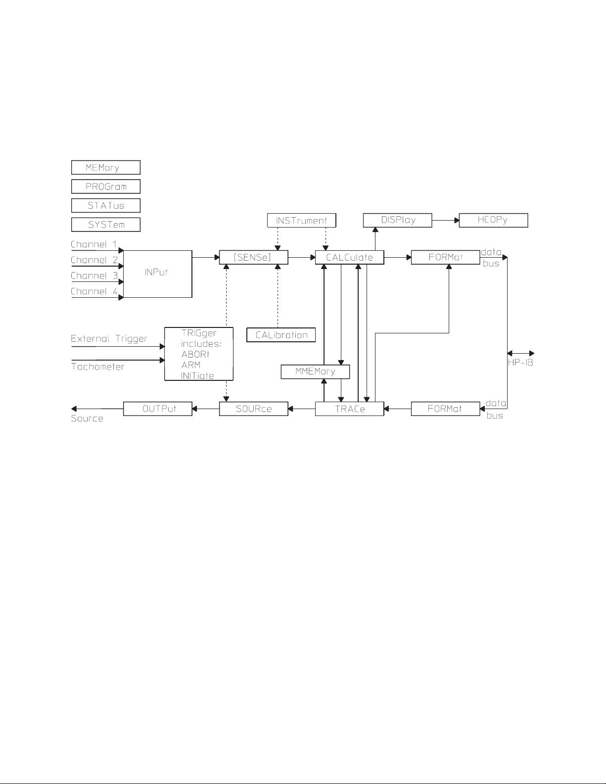
Finding the Right Command
Figure 2-2 shows the flow of control and measurement data through the Agilent 35670A. The SCPI
subsystems appear in the block diagram. Use figure 2-2 to help identify the subsystem containing a
command. For example, the location of the SENSe subsystem indicates it contains commands which
determine how measurement data is acquired. The use of the brackets ([ ]) indicates SENSe is an
implied mnemonic.
2-2. Flow of Control and Measurement Data
in the Agilent 35670A
2-4
Page 63

Command Syntax in the Agilent 35670A
Command Syntax in the Agilent 35670A
The Agilent 35670A uses program messages and response messages to communicate with other devices
on the GPIB. This section describes the syntax elements used in the command reference chapters. It also
describes the general syntax rules for both kinds of messages.
Note For a more detailed discussion of message syntax, including example program listings,
refer to the GPIB Programmer’s Guide.
Special Syntactic Elements
Several syntactic elements have special meanings:
colon (:) — When a command or query contains a series of keywords, the keywords are separated by
colons. A colon immediately following a keyword tells the command parser that the program
message is proceeding to the next level of the command tree. A colon immediately following a
semicolon tells the command parser that the program message is returning to the base of the
command tree. For more information, see “Programming with GPIB Commands” in the GPIB
Programmer’s Guide.
semicolon (;) — When a program message contains more than one command or query, a semicolon is
used to separate them from each other. For example, if you want to autorange the analyzer’s inputs
and then start a measurement using one program message, the message would be:
SENSE:VOLT:RANGE:AUTO ONCE;:ABORT;:INITIATE:IMMEDIATE
comma (,) — A comma separates the data sent with a command or returned with a response. For
example, the SYSTEM:TIME command requires three values to set the analyzer’s clock: one for
hours, one for minutes, and one for seconds. A message to set the clock to 8:45 AM would be:
SYSTEM:TIME 8,45,0
<WSP> — One white space is required to separate a program message (the command or query) from
its parameters. For example, the command “SYSTEM:TIME 8,45,0” contains a space between the
program header (SYSTEM:TIME) and its program data (8,45,0). White space characters are not
allowed within a program header.
For more information, see “GPIB Message Syntax” in the GPIB Programmer’s Guide.
2-5
Page 64

Command Syntax in the Agilent 35670A
Conventions
Syntax and return format descriptions use the following conventions:
< > Angle brackets enclose the names of items that need further definition. The definition will be
included in accompanying text. In addition, detailed descriptions of these elements appear at the end
of this chapter.
::= “is defined as” When two items are separated by this symbol, the second item replaces the first in
any statement that contains the first item. For example, A::=B indicates that B replace A in any
statement that contains A.
| “or” When items in a list are separated by this symbol, one and only one of the items can be chosen
from the list. For example, A|B indicates that A or B can be chosen, but not both.
... An ellipsis (trailing dots) is used to indicate that the preceding element may be repeated one or
more times.
[ ] Square brackets indicate that the enclosed items are optional.
{ } Braces are used to group items into a single syntactic element. They are most often used to
enclose lists and to enclose elements that are followed by an ellipsis.
Although the analyzer is not case sensitive, the case of letters in the command keyword is significant in
the Command Reference. Keywords that are longer than four characters can have a short form or a long
form. The analyzer accepts either form. Upper-case letters show the short form of a command keyword.
For more information, see “Programming with GPIB Commands” in the GPIB Programmer’s Guide.
The analyzer is sensitive to white space characters. White space characters are not allowed within
command keywords. They are only allowed when they are used to separate a command and a parameter.
A message terminator is required at the end of a program message or a response message. Use <NL>,
<^END>, or <NL> <^<END> as the program message terminator. The word <NL> is an ASCII new line
(line feed) character. The word <^END> means that End or Identify (EOI) is asserted on the GPIB
interface at the same time the preceding data byte is sent. Most programming languages send these
terminators automatically. For example, if you use the BASIC OUTPUT statement, <NL> is
automatically sent after your last data byte. If you are using a PC, you can usually configure your system
to send whatever terminator you specify.
For more information about terminating messages, see “Programming with GPIB Commands” in the
GPIB Programmer’s Guide.
2-6
Page 65

Command Syntax in the Agilent 35670A
Syntax Descriptions
Syntax descriptions in the command reference chapters use the following elements:
<BLOCK>
This item designates block data. There are three kinds of block data; binary-definite-length-block data,
binary-indefinite-length-block data, and ASCII data. The analyzer always returns binary definite-length-block
data or ASCII data in response to queries.
When you send block data to the analyzer, you can send it either as definite-length block or indefinite-length
block data or as ASCII data.
If you are sending binary data using indefinite-length syntax, <BLOCK> takes the following form:
<BLOCK> ::= #0<data_byte>[,<data_byte>] . . .<NL><^END>
<data_byte> ::= unsigned 8-bit data
<NL> ::= new line (line feed) character, ASCII decimal 10
<^END> ::= GPIB END message (EOI set true)
If you are sending binary data using definite-length syntax, <BLOCK> takes the following form:
<BLOCK> ::= #<byte><length_bytes><data_byte>[<data_byte>]...
<byte> ::= number of length bytes to follow (ASCII encoded)
<length_bytes> ::= number of data bytes to follow (ASCII encoded)
<data_byte> ::= unsigned 8-bit data
If you are sending ASCII data, <BLOCK> takes the following form:
<BLOCK> ::= integer[,integer]. . . <NL>
or
<BLOCK> ::= floating-point-numeric[,floating-point-numeric]. . . <NL>
See “GPIB Message Syntax” in the
information about block data.
<CHAR>
This item designates a string of ASCII characters. There are no delimiters. Usually, the string is from an
explicit set of responses. Maximum length is 12 characters.
<CMDSTR>
This string specifies the type of measurement data. Channels 3 and 4 are only available with Option AY6.
D[1|2| . . |8] selects a data register
TCAPture [1|2|3|4] selects a time capture buffer
W[1|2|. . .|8] selects a waterfall register
GPIB Programmer’s Guide
for more
XFRequency:POWer [1|2|3|4] selects power spectrum
XFRequency:POWer:COHerence [1,2|1,3|1,4|3,4] selects coherence
XFRequency:POWer:CROSs [1,2|1,3|1,4|3,4] selects cross spectrum
2-7
Page 66

Command Syntax in the Agilent 35670A
XFRequency:POWer:LINear [1|2|3|4] selects linear spectrum
XFRequency:POWer:RATio [2,1|3,1|4,1|4,3] selects frequency response
XFRequency:POWer:VARiance [1|2|3|4] selects normalized variance
XORDer:TRACk [1|2|3|4][,1|2|3|4|5] selects order track
XRPM:PROFile selects RPM profile
XTIMe:CORRelation [1|2|3|4] selects auto correlation
XTIMe:CORRelation:CROSs [1,2|1,3|1,4|3,4] selects cross correlation
XTIMe:VOLTage:CDF [1|2|3|4] selects cumulative density function
XTIMe:VOLTage:HISTogram [1|2|3|4] selects histogram
XTIMe:VOLTage:PDF [1|2|3|4] selects probability density function
XTIMe:VOLTage:WINDow [1|2|3|4] selects windowed time
XVOLtage:VOLTage [1,2|1,3|1,4|3,4] selects orbit
<DEF_BLOCK>
This item designates definite-length-block data which takes the following form if the data is binary encoded
(FORMat:DATA REAL command):
<DEF_BLOCK> ::= #<byte><length_bytes><data_byte>[<data_byte>]...
<byte> ::= number of length bytes to follow (ASCII encoded)
<length_bytes> ::= number of data bytes to follow (ASCII encoded)
<data_byte> ::= unsigned 8-bit data
If the data is ASCII encoded (FORMat:DATA ASCii command):
<DEF_BLOCK> ::= integer[,integer]...<NL>
or
<DEF_BLOCK> ::= floating-point-numeric[,floating-point-numeric]...<NL>
See “GPIB Message Syntax” in the
information about block data.
<EXPR>
This item designates an expression for a math function.
<EXPR> ::= ([<expr_element>]...)
<expr_element> ::= See the operations and operands listed below:
Operations:
AWEIGHT Apply A-weight filter
GPIB Programmer’s Guide
for more
BWEIGHT Apply B-weight filter
CWEIGHT Apply C-weight filter
CONJ Complex Conjugate
DIFF Differentiate
2-8
Page 67

DJOM Divide by j q
EXP Exponential
FFT Fast Fourier Transform
IFFT Inverse Fast Fourier Transform
INTEG Integrate
IMAG Imaginary Part
LN Natural Logarithm
MAG Magnitude
PSD Power Spectral Density
REAL Real Part
SQRT Square Root
XJOM multiply by j q
+ Add
- Subtract
Command Syntax in the Agilent 35670A
* Multiply
/ Divide
Operands:
D1|D2|...D8 Contents of data registers
F1|F2|...F5 Contents of function registers
K1|K2|...K5 Contents of constant registers
Measurement Data (depends on instrument mode)
[1|2|3|4] specifies which channel the data was taken from. Channels 3 and 4 are only available with Option
AY6.
PSPEC[1|2|3|4] Power Spectrum
LSPEC[1|2|3|4] Linear Spectrum
TIME[1|2|3|4] Time Data
WTIME[1|2|3|4] Windowed Time Data
FRES[21|31|41|43] Frequency Response
CSPEC[21|31|41|43] Cross Spectrum
COH[21|31|41|43] Coherence
HIST[1|2|3|4] Histogram (INST:SEL HIST only)
PDF[1|2|3|4] Probability Density Function (INST:SEL HIST only)
CDF[1|2|3|4] Cumulative Density Function (INST:SEL HIST only)
TIME[1|2|3|4] Unfiltered Time (INST:SEL HIST only)
2-9
Page 68

Command Syntax in the Agilent 35670A
ACORR[1|2|3|4] Autocorrelation (INST:SEL CORR only)
XCORR[21|31|41|43] Cross Correlation (INST:SEL CORR only)
CPOW[1|2|3|4] Composite Power (INST:SEL ORD only; Option 1D0)
TRACK[1|2|3|4|5] (INST:SEL ORD only; Option 1D0)
[1|2|3|4|5] specifies order track
TIME[1|2|3|4] Resampled Time (INST:SEL ORD only; Option 1D0)
RPM RPM Profile (INST:SEL ORD only; Option 1D0)
NVAR[1|2|3|4] Normalized Variance (INST:SEL SINE only; Option 1D2)
<FILE>
This string is used to describe the name of a file. It does not include any disk drive information.
The valid character set for <FILE> depends on the disk format.
DOS file names are limited to 8 ASCII characters followed by a period and a 3 ASCII character extension.
The period and extension are not required. File names are not case sensitive.
LIF file names are limited to 10 ASCII characters which may include all characters except “:” “<” and “|”.
are
The first character must be a letter. File names
case sensitive.
<FILENAME>
This string is used to describe the name of a file on the default disk, on the specified disk, or the specified disk
and DOS directory. The allowed form is:
“[PATH]filename”
where PATH must be replaced with:
“[MSIS:][\DOS_DIR\]”
where MSIS: must be replaced with:
RAM: which selects the volatile RAM disk.
NVRAM: which selects the non-volatile RAM disk.
INT: which selects the internal disk drive.
EXT[,<select_code>[,<unit_number>]]: which selects an external disk drive.
The brackets are not literal in the parameter. They indicate that the disk drive designation is optional. If the
disk drive is not specified, the default disk drive is used. Select the default specifier with the MMEM:MSIS
command.
DOS_DIR specifies a directory name (DOS only). DOS directory names are limited to ASCII characters. The
forward slash (/) may be used as a directory separator instead of the backward slash (\).
The brackets are not literal in the parameter. They indicate that the directory designation is optional. If the
director is not specified, the default directory is used. Select the default specifier with the MMEM:MSIS
command.
The valid character set for <FILENAME> depends on the disk format.
DOS file names are limited to 8 ASCII characters followed by a period and a 3 ASCII character extension.
not
The period and extension are not required. File names are
2-10
case sensitive.
Page 69

Command Syntax in the Agilent 35670A
LIF file names are limited to 10 ASCII characters which may include all characters except “:” “<” and “|”.
The first character must be a letter. File names
<MSINAME>
This item specifies the mass storage device. It is a <STRING> with one of the following values:
“RAM:”
“NVRAM:”
“INT:”
“EXT[,<select_code>[,<unit_number>]]:”
<MMEMNAME>
This item specifies a single file or an entire mass storage device. It takes the same form as <FILENAME>
except either the name of the file, the name of the mass storage device or both must be present. It can take one
of the following forms:
“[MSIS:][DOS_DIR:]filename”
“MSIS:”
“MSIS:[DOS_DIR:]filename”
are
case sensitive.
See the description for <FILENAME> for the valid mass storage device specifiers and the valid file name
character set. The optional directory specifier (DOS only) may be included with the filename.
<PROGRAM>
This item designates an Instrument BASIC program.
Load and save Instrument BASIC using the indefinite-length-block data format. The simplest way to load an
Instrument BASIC program into the analyzer is to send the command (PROG[:SELected]:DEFine) followed
by #0, followed by all the characters making up the program, including line numbers and linefeeds at the end
of each program statement.
Terminate the entire command with new line (line feed) character (ASCII decimal 10) and <^END> (the
GPIB END message (EOI set true) while the last byte of data is on the bus).
<STRING>
This item specifies any 8-bit characters delimited by single quotes or double quotes. The beginning and
ending delimiter must be the same. If the delimiter character is in the string, it must be entered twice. (For
example, to get “EXAMPLE”, enter “”EXAMPLE"".
2-11
Page 70

Page 71

Common Commands
3
Page 72

Page 73

Common Commands
This chapter describes all of the IEEE 488.2 common commands implemented by the Agilent 35670A.
An important property of all common commands is that you can send them without regard to a program
message’s position in the GPIB command tree.
For more information on the GPIB command tree, see chapter 2, “Programming with GPIB Commands,”
in the GPIB Programmer’s Guide.
3
3-1
Page 74

Common Commands
*CAL? query
Calibrates the analyzer and returns the result.
Query Syntax: *CAL?
Example Statements: OUTPUT 711;"*CAL?"
OUTPUT 711;"*cal?"
Return Format: Integer
Attribute Summary: Option: not applicable
Synchronization Required: no
Preset State: not applicable
SCPI Compliance: confirmed
Description:
The analyzer performs a full calibration when you send this query. If the calibration completes without
error, the analyzer returns 0. If the calibration fails, the analyzer returns 1.
This query is the same as the CAL:ALL? query.
3-2
Page 75

Common Commands
*CLS command
Clears the Status Byte by emptying the error queue and clearing all event registers.
Command Syntax: *CLS
Example Statements: OUTPUT 711;"*Cls"
OUTPUT 711;"*CLS"
Attribute Summary: Option: not applicable
Synchronization Required: no
Preset State: not applicable
SCPI Compliance: confirmed
Description:
This command clears the Status Byte register. It does so by emptying the error queue and clearing
(setting to 0) all bits in the event registers of the following register sets:
User Status
Device State
Questionable Voltage
Limit Fail
Questionable Status
Standard Event
Operation Status
In addition, *CLS cancels any preceding *OPC command or query. This ensures that bit 0 of the
Standard Event register will not be set to 1 and that a response will not be placed in the analyzer’s output
queue when pending overlapped commands are completed.
*CLS does not change the current state of enable registers or transition filters.
Note To guarantee that the Status Byte’s Message Available and Master Summary Status bits
are cleared, send *CLS immediately following a Program Message Terminator.
See chapter 1 for more information on the Status Byte register.
3-3
Page 76

Common Commands
*ESE command/query
Sets bits in the Standard Event enable register.
Command Syntax: *ESE <number>|<bound>
<number> ::= a real number (NRf data)
limits: 0:255
<bound> ::= MAX|MIN
Example Statements: OUTPUT 711;"*ese 128"
OUTPUT 711;"*ESE 60"
Query Syntax: *ESE?
Return Format: Integer
Attribute Summary: Option: not applicable
Synchronization Required: no
Preset State: dependent on setting of *PSC
SCPI Compliance: confirmed
Description:
This command allows you to set bits in the Standard Event enable register. Assign a decimal weight to
each bit you want set (to 1) according to the following formula:
(bit_number)
2
with acceptable values for bit_number being 0 through 7. Add the weights and then send the sum with
this command.
When an enable register bit is set to 1, the corresponding bit of the Standard Event event register is
enabled. All enabled bits are logically ORed to create the Standard Event summary, which reports to bit
5 of the Status Byte. Bit 5 is only set to 1 if both of the following are true:
One or more bits in the Standard Event event register are set to 1.
At least one set bit is enabled by a corresponding bit in the Standard Event enable register.
The setting last specified with *ESE is saved in nonvolatile memory. It can be recalled at power-up,
depending on the setting of the Power-on Status Clear flag (set with *PSC). When the flag is 0 at
power-up, all bits in the Standard Event enable register are set according to the saved *ESE value. When
the flag is 1 at power-up, all bits in the Standard Event enable register are initialized to 0.
The query returns the current state of the Standard Event enable register. The state is returned as a sum of
the decimal weights of all set bits.
For more information on the Standard Event register set, see chapter 1.
3-4
Page 77

Common Commands
*ESR? query
Reads and clears the Standard Event event register.
Query Syntax: *ESR?
Example Statements: OUTPUT 711;"*esr?"
OUTPUT 711;"*Esr?"
Return Format: Integer
Attribute Summary: Option: not applicable
synchronization Required: no
Preset State: +0
SCPI Compliance: confirmed
Description:
This query returns the current state of the Standard Event event register. The state is returned as a sum of
the decimal weights of all set bits. The decimal weight for each bit is assigned according to the following
formula:
(bit_number)
2
with acceptable values for bit_number being 0 through 7.
The query clears the register after it reads the register.
A bit in this register is set to 1 when the condition it monitors becomes true. A set bit remains set,
regardless of further changes in the condition it monitors, until one of the following occurs:
You read the register with this query.
You clear all event registers with the *CLS command.
For more information on the Standard Event register set, see chapter 1.
3-5
Page 78

Common Commands
*IDN? query
Returns a string that uniquely identifies the analyzer.
Query Syntax: *IDN?
Example Statements: OUTPUT 711;"*IDN?"
OUTPUT 711;"*idn?"
Return Format: Agilent Technologies,35670A,<serial_number><software_re
vision>
Attribute Summary: Option: not applicable
Synchronization Required: no
Preset State: instrument dependent
SCPI Compliance: confirmed
Description:
The response to this query uniquely identifies your analyzer.
-
3-6
Page 79

Common Commands
*OPC command/query
Sets or queries completion of all pending overlapped commands.
Command Syntax: *OPC
Example Statements: OUTPUT 711;"*Opc"
OUTPUT 711;"*OPC"
Query Syntax: *OPC?
Return Format: Integer
Attribute Summary: Option: not applicable
Synchronization Required: no
Preset State: not applicable
SCPI Compliance: confirmed
Description:
Some commands are processed sequentially by the analyzer. A sequential command holds off the
processing of subsequent commands until it has been completely processed. However, some commands
do not hold off the processing of subsequent commands. These commands are called overlapped
commands. At times, overlapped commands require synchronization. The Attribute Summary for each
command indicates whether it requires synchronization.
The analyzer uses the No Pending Operation (NPO) flag to keep track of overlapped commands that are
still pending (that is, not completed). The NPO flag is reset to 0 when an overlapped command is
pending. It is set to 1 when no overlapped commands are pending. You cannot read the NPO flag
directly, but you can use *OPC and *OPC? to tell when the flag is set to 1.
If you use *OPC, bit 0 of the Event Status event register is set to 1 when the NPO flag is set to 1. This
allows the analyzer to generate a service request when all pending overlapped commands are completed
(assuming you have enabled bit 0 of the Event Status register and bit 5 of the Status Byte register).
If you use *OPC?, +1 is placed in the output queue when the NPO flag is set to 1. This allows you to
effectively pause the controller until all pending overlapped commands are completed. It must wait until
the response is placed in the queue before it can continue.
3-7
Page 80

Common Commands
Note The *CLS and *RST commands cancel any preceding *OPC command or query.
Pending overlapped commands are still completed, but you can no longer determine
when.
Two GPIB bus management commands—Device Clear (DCL) and Selected Device
Clear (SDC)—also cancel any preceding *OPC command or query.
A list of overlapped commands requiring synchronization appear in chapter 1. See “Synchronization” in
the GPIB Programmer’s Guide for additional information abaout the *OPC command and the *OPC?
query.
3-8
Page 81

Common Commands
*OPT? query
Returns a string that identifies the analyzer’s option configuration.
Query Syntax: *OPT?
Example Statements: OUTPUT 711;"*opt?"
OUTPUT 711;"*Opt?"
Return Format: “1D1,1D2,1D3,1D4,1C2,AN2,AY6"
Attribute Summary: Option: not applicable
Synchronization Required: no
Preset State: instrument dependent
SCPI Compliance: confirmed
Description:
The response to this query identifies the analyzer’s option configuration. For example, if your analyzer
has Computed Order Tracking installed, it returns 1D0 to this query. Options are identified by the
following:
1D0 Computed Order Tracking
1D1 Real Time Octave Measurements
1D2 Swept Sine Measurements
1D3 Curve Fit / Synthesis
1D4 Arbitrary Source
1C2 Instrument BASIC
AY6 Add 2 Input Channels
UFF Add 1 MByte Nonvolatile RAM
AN2 Add 4 MBytes Memory
UFC Add 8 MBytes Memory
The query returns a null string (“”"") if special options are not installed in the analyzer.
3-9
Page 82

Common Commands
*PCB command
Sets the pass-control-back address.
Command Syntax: *PCB <primary_address>, [<secondary_address>]
<primary_address> ::= <number>|<step>|<bound>
<secondary_address> ::= <number>|<step>|<bound>
Example Statements: OUTPUT 711;"*PCB 11"
OUTPUT 711;"*PCB 19"
Attribute Summary: Option: not applicable
Synchronization Required: no
Preset State: not affected by Preset
SCPI Compliance: confirmed
Description:
Use this command to specify the address of your controller before you pass control of the GPIB to the
analyzer. When the analyzer completes the operation that required it to have control of the bus, it
automatically passes control back to the controller at the specified address.
The optional second number is only used for controllers that support extended addressing. It is ignored
by the analyzer.
The address last specified with this command is saved in nonvolatile memory, so it is not affected when
you turn the analyzer off and on. It is also not affected by the *RST command.
3-10
Page 83

Common Commands
*PSC command/query
Sets the state of the Power-on Status Clear flag.
Command Syntax: *PSC <number>|<bound>
<number> ::= a real number (NRf data)
limits: -32767:32767
<bound> ::= MAX|MIN
Example Statements: OUTPUT 711;"*PSC 1"
OUTPUT 711;"*ESE 1;*SRE 16;*PSC 0" ! Generate SRQ on
! powerup
Query Syntax: *PSC?
Return Format: Integer
Attribute Summary: Option: not applicable
Synchronization Required: no
Preset State: not affected by Preset
SCPI Compliance: confirmed
Description:
This command lets you specify whether or not the Service Request enable register and the Event Status
enable register should be cleared (all bits reset to 0) at power-up.
The settings of the Service Request enable register and the Event Status enable register are saved in
nonvolatile memory when you turn the analyzer off. These settings can be recalled when you turn the
analyzer on, but only if the Power-on Status Clear (PSC) flag is reset to 0. When the PSC flag is set to 1,
the two enable registers are cleared at power-up. Use *PSC to specify the state of the PSC flag.
The number last specified with *PSC is saved in nonvolatile memory, so it is not affected when you turn
the analyzer off and on. It is also not affected by the *RST command.
If you want the analyzer to generate a service request at power-up, bit 7 of the Event Status enable
register and bit 5 of the Service Request enable register must be set. This is only possible if the PSC flag
is reset to 0.
The query returns the current state of the PSC flag.
3-11
Page 84

Common Commands
*RST command
Executes a device reset.
Command Syntax: *RST
Example Statements: OUTPUT 711;"*RST"
OUTPUT 711;"*rst"
Attribute Summary: Option: not applicable
Synchronization Required: yes
Preset State: not applicable
SCPI Compliance: confirmed
Description:
This command returns the analyzer to a reset state. In addition, *RST cancels any pending *OPC
command or query.
The reset state is similiar to the preset state. The preset state of each command is listed in the Attribute
Summary. In some cases, however, a command’s reset state differs from its preset state. These
commands (and their reset states) are listed below.
CALibration:AUTO is set to 0 (OFF).
FREQuency:SPAN:LINK is set to CENTer.
FREQuency:RESolution:AUTO is ON.
CALCulate:GDAPerture:APERture is set to 0.25 PCT.
HCOPy:PAGE:DIMensions:USER:LLEFt is set to +332, +1195.
HCOPy:PAGE:DIMensions:USER:URIGht is set to +9155, +7377.
Note This command is not equivalent to a front panel preset. Send SYST:PRES if you want
to send a command that is equivalent to a front panel preset.
3-12
Page 85
The following are not affected by this command:
The state of the Power-on Status Clear flag.
The state of all enable and transition registers.
The GPIB input and output queues.
The time and date (SYST:TIME and SYST:DATE).
The GPIB address settings (SYST:COMM:GPIB:ADDR, HCOP:PLOT:ADDR,
HCOP:PRIN:ADDR).
The GPIB controller capability setting.
The default disk selection (MMEM:MSIS).
The serial interface (RS-232-C) parameters (set with SYST:COMM:SERial commands).
Common Commands
Contents of limit and data registers.
Contents of math function and constant registers.
Contents of the RAM disks.
Calibration constants.
Contents of the time capture buffer.
The external keyboard setup.
3-13
Page 86

Common Commands
*SRE command/query
Sets bits in the Service Request enable register.
Command Syntax: *SRE <number>|<bound>
<number> ::= a real number (NRf data)
limits: 0:255
<bound> ::= MAX|MIN
Example Statements: OUTPUT 711;"*sre 40"
OUTPUT 711;"*Sre 17"
Query Syntax: *SRE?
Return Format: Integer
Attribute Summary: Option: not applicable
Synchronization Required: no
Preset State: dependent on setting of *PSC
SCPI Compliance: confirmed
Description:
This command allows you to set bits in the Service Request enable register. Assign a decimal weight to
each bit you want set (to 1) according to the following formula:
(bit_number)
2
with acceptable values for bit_number being 0 through 7. Add the weights and then send the sum with
this command.
Note The analyzer ignores the setting you specify for bit 6 of the Service Request enable
register. This is because the corresponding bit of the Status Byte register is always
enabled.
The analyzer requests service from the active controller when one of the following occurs:
A bit in the Status Byte register changes from 0 to 1 while the corresponding bit of the Service
Request enable register is set to 1.
A bit in the Service Request enable register changes from 0 to 1 while the corresponding bit of the
Status Byte register is set to 1.
3-14
Page 87

Common Commands
The setting last specified with *SRE is saved in nonvolatile memory. It can be recalled at power-up,
depending on the setting of the Power-on Status Clear flag (set with *PSC). When the flag is 0 at
power-up, all bits in the Service Request enable register are set according to the saved *SRE value.
When the flag is 1 at power-up, all bits in the Service Request enable register are initialized to 0.
The query returns the current state of the Service Request enable register. The state is returned as a sum
of the decimal weights of all set bits.
3-15
Page 88

Common Commands
*STB? query
Reads the Status Byte register.
Query Syntax: *STB?
Example Statements: OUTPUT 711;"*Stb?"
OUTPUT 711;"*STB?"
Return Format: Integer
Attribute Summary: Option: not applicable
Synchronization Required: no
Preset State: variable
SCPI Compliance: confirmed
Description:
This command allows you to set bits in the Status Byte register. The state is returned as a sum of the
decimal weights of all set bits. The decimal weight for each bit is assigned according to the following
formula:
(bit_number)
2
with acceptable values for bit_number being 0 through 7.
The register is not cleared by this query. To clear the Status Byte register, you must send the *CLS
command.
Bits in the Status Byte register are defined as follows:
Bit 0 summarizes all enabled bits of the User Status register.
Bit 1 is reserved.
Bit 2 summarizes all enabled bits of the Device State register.
Bit 3 summarizes all enabled bits of the Questionable Status register.
Bit 4 is the Message Available (MAV) bit. It is set whenever there is something in the analyzer’s
output queue.
Bit 5 summarizes all enabled bits of the Standard Event Status register.
3-16
Page 89

Common Commands
Bit 6, when read with this query (*STB?), acts as the Master Summary Status (MSS) bit. It
summarizes all enabled bits of the Status Byte register. (Bit 6 acts as the Request Service (RQS) bit
when it is read by a serial poll.
Bit 7 summarizes all enabled bits of the Operation Status register.
For more information on the Status Byte register, see chapter 1.
3-17
Page 90

Common Commands
*TRG command
Triggers the analyzer when TRIG:SOUR is BUS.
Command Syntax: *TRG
Example Statements: OUTPUT 711;"*trg"
OUTPUT 711;"*Trg"
Attribute Summary: Option: not applicable
Synchronization Required: no
Preset State: not applicable
SCPI Compliance: confirmed
Description:
This command triggers the analyzer when the following two conditions are met:
The GPIB is designated as the trigger source. (See the TRIG:SOUR BUS command.)
The analyzer is waiting to trigger. (Bit 5 of the Operation Status register must be set). It is ignored at
all other times.
The *TRG command has the same effect as TRIG:IMM. It also has the same effect as the GPIB bus
management command Group Execute Trigger (GET).
3-18
Page 91

Common Commands
*TST? query
Tests the analyzer hardware and returns the results.
Query Syntax: *TST?
Example Statements: OUTPUT 711;"*TST?"
OUTPUT 711;"*tst?"
Return Format: Integer
Attribute Summary: Option: not applicable
Synchronization Required: no
Preset State: not applicable
SCPI Compliance: confirmed
Description:
The analyzer’s self-test performs a full calibration and then compares the calibration results to specified
limits. If the results are within specified limits, the analyzer returns 0. If the results exceed the specified
limits, the analyzer returns 1.
3-19
Page 92

Common Commands
*WAI command
Holds off processing of subsequent commands until all preceding commands have been processed.
Command Syntax: *WAI
Example Statements: OUTPUT 711;"*Wai"
OUTPUT 711;"*WAI"
Attribute Summary: Option: not applicable
Synchronization Required: no
Preset State: not applicable
SCPI Compliance: confirmed
Description:
Use *WAI to hold off the processing of subsequent commands until all pending overlapped commands
have been completed.
Some commands are processed sequentially by the analyzer. A sequential command holds off the
processing of any subsequent commands until it has been completely processed. However, some
commands do not hold off the processing of subsequent commands; they are referred to as overlapped
commands. *WAI ensures that overlapped commands are completely processed before subsequent
commands (those sent after *WAI) are processed.
See “Synchronization” in the GPIB Programmer’s Guide for additional information about the use of
*WAI and overlapped commands.
3-20
Page 93

ABORt
4
Page 94

Page 95

ABORt
This subsystem contains one command which aborts any measurement process.
4
4-1
Page 96

ABORt
ABORt command
Stops the current measurement in progress.
Command Syntax: ABORt
Example Statements: OUTPUT 711;"abor"
OUTPUT 711;"Abort"
Attribute Summary: Option: not applicable
Synchronization Required: no
Preset State: not applicable
SCPI Compliance: confirmed
Description:
This command aborts any measurement in progress and resets the trigger system. ABOR forces the
trigger system to an idle state. ABORt forces the Measuring bit (bit 4) and the Averaging bit (bit 8) of the
Operation Status register to 0. To restart a measurement you must send the INIT:IMM command.
The program message ABOR;:INIT:IMM serves a special synchronization function. When you send this
message to restart a measurement, the analyzer’s No Pending Operation (NPO) flag is set to 1 until the
measurement is complete. The two commands that test the state of this flag—*WAI and *OPC—allow
you to hold off subsequent actions until the measurement is complete. See chapter 3 of the GPIB
Programmer’s Guide for more information about synchronization.
Note When averaging is on ([SENSe:]AVERage[:STATe] ON) the NPO flag is not set to 1
until n measurements have been combined into one trace. You specify the value of
with the[SENSe:] AVER:COUNt command.
n
4-2
Page 97

ARM
5
Page 98

Page 99
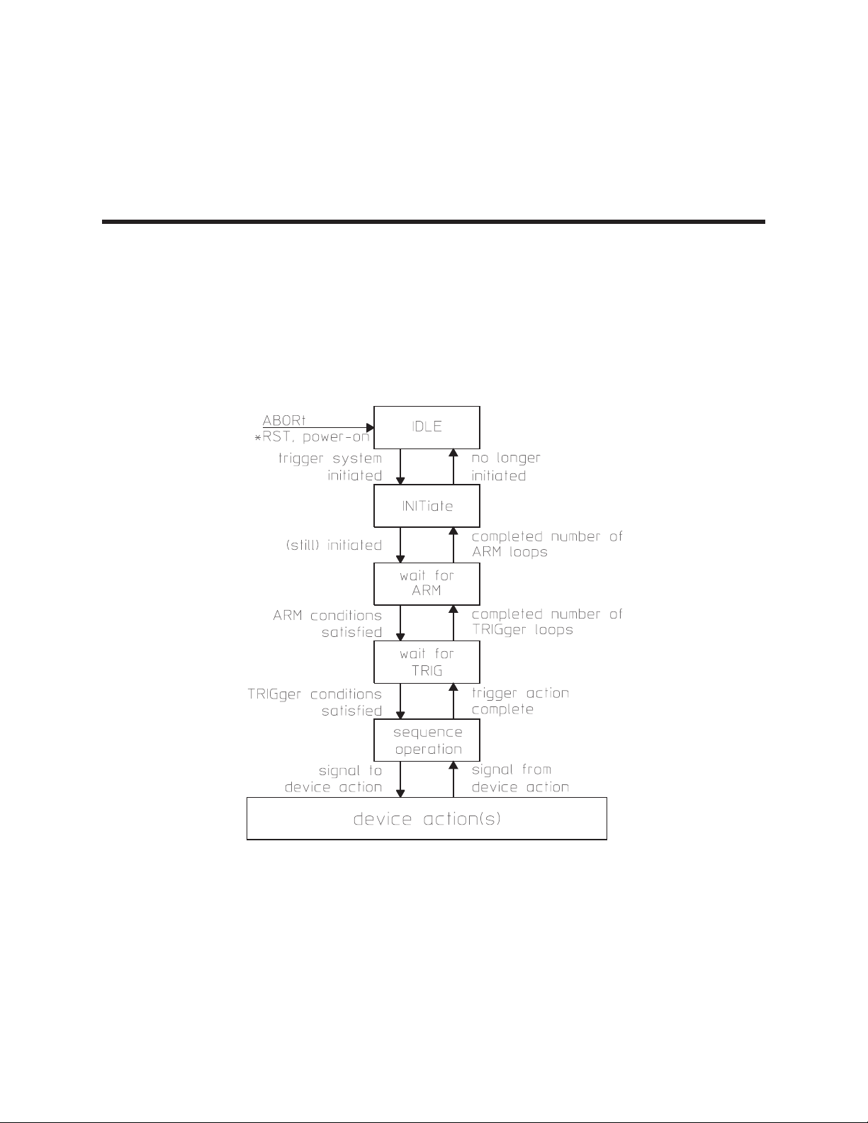
ARM
This subsystem contains commands that control the analyzer’s trigger-arming functions. See the
TRIGger subsystem for commands related to other triggering functions.
Figure 5-1 shows the model for the Agilent 35670A’s ARM-INITiate-TRIGger functions.
5
Figure 5-1. The Agilent 35670A's ARM-INIT-TRIG Functions
5-1
Page 100

ARM
ARM[:IMMediate] command
Arms the trigger if ARM:SOUR is MAN.
Command Syntax: ARM[:IMMediate]
Example Statements: OUTPUT 711;":ARM"
OUTPUT 711;"arm:imm"
Attribute Summary: Option: not applicable
Synchronization Required: no
Preset State: not applicable
SCPI Compliance: confirmed
Description:
Two conditions must be met before this command arms the trigger.
Manual arming must be selected (ARM:SOUR is MAN).
Bit 1 (Settling) or bit 6 (RDY for ARM) of the Operation Status condition register must be set to 1.
ARM:IMM is ignored at all other times.
For more information about how to use status registers, see “Programming the Status System” in the
GPIB Programmer’s Guide.
5-2
 Loading...