

Page 1

About this Manual
We’ve added this manual to the Agilent website in an effort to help you support
your product. This manual is the best copy we could find; it may be incomplete
or contain dated information. If we find a more recent copy in the future, we will
add it to the Agilent website.
Support for Your Product
Agilent no longer sells or supports this product. Our service centers may be able
to perform calibration if no repair parts are needed, but no other support from
Agilent is available. You will find any other available product information on the
Agilent Test & Measurement website, www.tm.agilent.com.
HP References in this Manual
This manual may contain references to HP or Hewlett-Packard. Please note that
Hewlett-Packard's former test and measurement, semiconductor products and
chemical analysis businesses are now part of Agilent Technologies. We have
made no changes to this manual copy. In other documentation, to reduce
potential confusion, the only change to product numbers and names has been in
the company name prefix: where a product number/name was HP XXXX the
current name/number is now Agilent XXXX. For example, model number
HP8648A is now model number Agilent 8648A.
Page 2

Logic Analysis System
Reference Manual
HP 16500A/16501A
Logic Analysis System
Copyright Hewlett Packard Company 1987, 1990
Manual Set Part Number 16500-90912
Microfiche Part Number 16500-90812
Printed in U.S.A November 1990
Page 3

First Edition - September 1987
Second Edition - November 1990
Printed in U.S.A.Printing History
Page 4

Product
Warranty
This Hewlett-Packard product has a warranty against defects in material
and workmanship for a period of 1 year from date of shipment. During
warranty period, Hewlett-Packard Company will, at its option, either
repair or replace products that prove to be defective.
For warranty service or repair,thisproduct must be returned to a service
facility designated by Hewlett-Packard. However, warranty service for
products installed by Hewlett-Packard and certain other products
designated by Hewlett-Packard will be performed at Buyer’s facility at no
charge within the Hewlett-Packard service travel area. Outside
Hewlett-Packard service travel areas, warranty service will be performed
at Buyer’s facility only upon Hewlett-Packard’s prior agreement and
Buyer shall pay Hewlett-Packard’s round trip travel expenses.
For products returned to Hewlett-Packard for warranty service, the Buyer
shall prepay shipping charges to Hewlett-Packard and Hewlett-Packard
shall pay shipping charges to return the product to the Buyer. However,
the Buyer shall pay all shipping charges, duties, and taxes for products
returned to Hewlett-Packard from another country.
Hewlett-Packard warrants that its software and firmware designated by
Hewlett-Packard for use with an instrument will execute its programming
instructions when properly installed on that instrument. Hewlett-Packard
does not warrant that the operation of the instrument, software,or
firmware will be uninterrupted or error-free.
Limitation of
Warranty
The foregoing warranty shall not apply to defects resulting from improper
or inadequate maintenance by the Buyer, Buyer-supplied software or
interfacing, unauthorized modification or misuse, operation outside of the
environmental specifications for the product, or improper site preparation
or maintenance.
NO OTHER WARRANTY IS EXPRESSED OR IMPLIED.
HEWLETT-PACKARD SPECIFICALLY DISCLAIMS THE IMPLIED
WARRANTIES OF MERCHANTABILITY AND FITNESS FOR A
PARTICULAR PURPOSE.
Page 5

Exclusive
Remedies
THE REMEDIES PROVIDED HEREIN ARE BUYER’S SOLE AND
EXCLUSIVE REMEDIES. HEWLETT-PACKARD SHALL NOT BE
LIABLE FOR ANY DIRECT, INDIRECT, SPECIAL, INCIDENTAL,
OR CONSEQUENTIAL DAMAGES, WHETHER BASED ON
CONTRACT, TORT, OR ANY OTHER LEGAL THEORY.
Assistance Product maintenance agreements and other customer assistance
agreements are available for Hewlett-Packard products.
For assistance, contact your nearest Hewlett-Packard Sales and Service
Office. Addresses are provided at the back of this operating manual.
Certification Hewlett-Packard Company certifies that this product met its published
specifications at the time of shipment from the factory. Hewlett-Packard
further certifies that its calibration measurements are traceable to the
United States National Bureau of Standards, to the extent allowed by the
Bureau’s calibration facility, and to the calibration facilities of other
International Standards Organization members.
Safety This product has been designed and tested according to International
Safety Requirements. To ensure safe operation and to keep the product
safe, the information, cautions, and warnings in this operating manual
must be heeded.
Page 6

Introduction
Welcome to the Hewlett-Packard Logic Analysis System! The HP
16500A/16501A LogicAnalysis System has been designedto be the
easiest system to use, ever. Its modular mainframeallows you to
configure the HP 16500A/16501A with just the modules you want and
add additional modules later.
This manual explains the operation of the System and Intermodule menus
of the HP 16500A/16501A Logic AnalysisSystem. It is organized like an
encyclopedia, breaking down the functions and features into their major
sections, and giving more of a conceptual example of their different
applications. The manual is laid out so you can find your information
quickly and easily.
Chapter 1 introduces the HP 16500A/16501A by summarizing the features
of the instruments.
Chapter 2 introduces the user interfaces and shows you how easy they are
to use. This chapter provides a step-by-step tutorial on operating the user
interfaces.
Chapter 3 describes the optional keyboard interface, detailing the
functions of the keys and explaining the use of the keyboard overlays.
Chapters 4 and 5 discuss the features of the System Configuration menu,
including the HP-IB and RS-232C interfaces for hardcopy capabilities and
controller interface.
Chapter 6 describesthe features, components, and system configuration of
the optional HP 16501A expansion frame.
Chapter 7 explains how to output screen displays from the HP 16500A to
various HP-IB and RS-232C graphics printers.
Chapter 8 explains the disk operations of the HP 16500A/16501A and tells
you how to get into the system’s Front and Read Disk menus.
Chapters 9, 10, and 11 describe the System Utilities menu and the touch
calibration and color selection capabilities available through the menu.
Page 7

Chapter 12 introduces you to the intermodule measurement capabilities of
the HP 16500A/16501A and gives several examples of possible
applications.
Appendix A lists the general characteristics of the HP 16500A/16501A.
Appendices B and C cover repacking and general maintenance for the
HP16500/16501A.
Appendix D describes the self-test that is performed when the HP
16500A/16501A is turned on.
Appendix E lists the different error messages of the System Disk menus,
briefly describing what each means.
Appendix F explains how to install and remove cards for individual
modules.
Appendix G explains how to create a system disk.
If you haven’t already read the manual Setting Up The HP 16500 Logic
Analysis System, please read it before continuing.
Page 8

Table of Contents
Chapter 1 What Is the HP 16500A/16501A Logic Analysis System?
1-1 Key Features
1-2 Optional Features
1-2 User Interfaces
1-3 Default Configurations
1-4 Storing Default Configurations
Chapter 2 Learning to Use the HP 16500A/16501A
2-1 TheDisplay
2-3 User Interfaces
2-4 TheTouchscreen
2-4 Types of Fields
2-5 Pop-Up Menus
2-6 Pattern Fields
2-7 Multiple-Choice Listings
2-7 Toggle Fields
2-8 Immediate-Action Fields
2-8 Knob/Numeric Fields
2-9 Alphanumeric Keypads
2-9 Entering Information with the Keypad
2-10 The Optional Mouse
2-10 Connecting the Mouse
2-13 Disconnecting the Mouse
2-13 The Optional Keyboard
2-13 Connecting the Keyboard
2-15 Disconnecting the Keyboard
2-15 The Knob
2-15 The Cursor
2-16 Exercises
Contents-1
Page 9

Table of Contents (Continued)
Chapter 3 Using the Optional Keyboard Interface
3-1 Moving the Cursor
3-1 Cursor Keys
3-1 Tab Key
3-2 Home Key
3-2 Next and Previous Keys
3-2 Selecting a Menu Item
3-2 Entering Data into a Menu
3-3 Autoroll
3-4 Using the Keyboard Overlays
3-5 Don’t Care Key
3-5 Function Keys
3-6 Defining Time Units
3-6 Defining Voltage Units
3-7 Assigning Edge Triggers
3-7 Closing a Menu
Chapter 4 The System Configuration Menu
4-1 Getting into the System Configuration Menu
4-2 Layout of the System Configuration Menu
4-4 Slot Designators
4-5 Menu Map
Chapter 5 HP-IB and RS-232C
5-1 The Controller Interface
5-1 The Printer Interface
5-1 What Is the HP-IB Interface?
5-2 SelectinganAddress
5-2 What Is the RS-232C Interface?
5-2 Baud Rate
5-3 Stop Bits
5-3 Parity
5-4 Data Bits
5-4 Protocol
5-5 Configuring the Interface for a Controller or a Printer
Contents-2
Page 10

Table of Contents (Continued)
Chapter 6 The Optional HP 16501A Expansion Frame
6-1 Features
6-1 Component Details
6-1 Expansion Frame Interface Board
6-2 Main Frame Interface Board
6-2 System Configuration
6-3 System Arming and Triggering
6-5 Connecting the HP 16501A Expansion Frame
Chapter 7 Connecting a Printer
7-1 HP-IB Printers
7-1 HP-IB Printer Setup
7-3 HP-IB Configuration
7-4 RS-232C Printers
7-4 RS-232C Printer Setup
7-6 RS-232C Configuration
7-8 Configuration Example
7-8 Connecting to Other Hewlett-Packard Printers
7-10 Printing the Display
Chapter 8 The System Front and Rear Disk Menus
8-1 Getting into the System Front Disk Menu
8-2 The Disk Operations
8-4 Menu Map
8-5 Selecting a Disk Operation
8-6 Disk Operation Parameters
8-7 Source and Destination Disks
8-8 Installing a Disk
8-9 Formatting a Disk
8-11 Storing on a Disk
8-15 The Load Operation
8-18 Renaming a File
8-20 The Autoload Operation
8-22 Purging a File
8-23 Copying a File
Contents-3
Page 11

Table of Contents (Continued)
8-26 The Pack Disk Operation
8-26 Duplicating a Disk
Chapter 9 The System Utilities Menu
9-1 Getting into the System Utilities Menu
9-2 Layout of the System Utilities Menu
9-3 Menu Map
Chapter 10 The Touch and Sound Fields of the System Utilities Menu
10-1 Getting into the System Utilities Menu
10-2 Touch Calibration
10-4 Touch On
10-5 Sound On
Chapter 11 Display Color Selection (System Utilities Menu)
11-1 Getting into the System Utilities Menu
11-2 The Color Model
11-4 Selecting the Color, Hue, Saturation, and Luminosity Fields
11-6 The Color Field
11-8 Returning to the Default Colors
Chapter 12 Intermodule Measurements
12-1 Why Use Intermodule Measurements?
12-1 Getting into the Intermodule Menu
12-2 The IntermoduleMenu
12-4 Menu Map
12-5 What Happens When You Touch Group Run?
12-5 For the HP 16500A Alone
12-6 For the HP 16500A With the HP 16501A Attached
12-7 What Are Some Typical Intermodule Measurements?
12-8 Example 1: Analyzing a Glitch
12-9 Example 2: Analyzing Interrupt Handling in a CPU System
12-10 Example 3: A Simple Stimulus/ Response System
Contents-4
Page 12

Table of Contents (Continued)
12-11 How Are Intermodule Measurements Set Up?
12-12 The Group Run Configuration Field
12-13 The Group Run/Stop Field
12-14 The Modules
12-15 PORT OUT
12-16 Status Indicators and Time Correlation Bars
12-17 The Skew Menu
12-18 Displaying Multiple Module Data on One Screen
12-21 Helpful Hints
12-21 Exercise
Appendix A General Characteristics
A-1 Interface
A-3 Hardware Connectivity
A-4 Programmability
A-4 Hardcopy Capability
A-4 Input/Output Rear-PanelBNCs
A-5 Interactive Measurements
A-6 Operating Environment
A-6 Ventilation Requirements
A-7 Power Requirements
A-7 Weight
A-7 Dimensions
Appendix B Repackaging for Shipment
B-1 The Storage and Shipment Environment
B-1 Tagging the Instrument for Service
B-1 Repacking the Instrument
Appendix C C-1 Maintaining the HP 16500A/16501A
C-1 Cleaning Requirements
C-1 Degaussing
C-2 Service and Calibration
C-3 The System Test Menu
Contents-5
Page 13

Table of Contents (Continued)
Appendix D D-1 Self-Test Documentation
D-2 Fail Codes
D-2 Critical Errors
D-3 Non-Critical Errors
Appendix E E-1 Disk Error Messages
E-1 Disk Error Messages
E-3 Disk Warning Messages
Appendix F F-1 Installing and Removing Cards
F-1 Where Do Cards Mount?
F-3 Installing Cards in the HP 16500A/16501A
F-5 Removing Cards from the HP 16500A/16501A
Appendix G G-1 Creating a System Disk
G-1 What Files are Required on the System Disk?
G-2 Creating a New System Disk
G-3 Adding a Module to the System Disk
G-4 Updating a System Disk
G-7 What Is a System Performance Verification Disk?
Contents-6
Page 14

What Is the HP 16500A/16501A Logic
Analysis System?
The HP 16500A is the mainframe of the Hewlett-Packard Logic Analysis
System. It offers a modular structure for plug-in cards with a wide range
of state, timing, oscilloscope, and pattern generator capabilities. This
allows you to configure the HP 16500A using only the modules you need
in order to perform a desired measurement or set of measurements, while
giving you the flexibility to change or update them later.
The HP 16501A is the add-on mainframe for expanding the module
capacity of the HP 16500A. When the HP 16501A is connected to the HP
16500A, they function as a single nine-card system which is turned on and
controlled by the HP 16500A. The HP 16501A forms a tightly coupled
system with the HP 16500A, permitting each of the two mainframes to
arm or trigger any module from any other module.
The Logic Analysis System provides both experienced and first-time users
with powerful measurement capabilities. The pop-up menus and color
graphics lead you through setups and measurements quickly and easily,
without the need to memorize a lot of steps. By touching the appropriate
fields or using the cursor of either the optionalmouse or keyboard, you
can perform functions, configure menus, and move from one menu to
another.
1
With the intermodule capabilities of the Logic Analysis System, you can
make interactive measurements between modules. This allows you to
configure modules to interact with each other, using the triggering
capabilities of one module and the acquisition capabilities of another to
make measurements.
Key Features The key features of the HP 16500A are:
• Modular mainframe with five card slots.
• 9-inch color monitor.
• Touchscreen.
• Dual 3.5-inch flexible disk drives.
What Is the HP 16500A/16501A Logic Analysis System?
1-1
Page 15

• Intermodule triggering and time correlation of gathered data.
• HP-IB and RS-232C interfaces for:
— Hardcopy output to a printer
— Controller interface.
Optional
Features
The optional features of the HP 16500A/16501A are:
• Modular mainframe with nine card slots (HP 16501A connectedto
the HP 16500A).
• Mouse.
• Keyboard.
User Interfaces The HP 16500A/16501A has four user interface devices: the knob on the
front panel, the touchscreen, the optional mouse, and the optional
keyboard.
The knob on the front panel is used to move the cursor on certain menus,
increment or decrement numeric fields, and to roll the display.
The touchscreen fields can be selected by touch or with the optional
mouse or keyboard. To activate a field by touch, press the field (the dark
blue box) on the display with your finger until the field changes color.
Then move your finger away from the screen to activate your selection.
To activate a field with the optional mouse, position the cursor (+) of the
mouse over the desired field and press the button on the upper-left corner
of the mouse.
To activate a field using the optional keyboard, position the keyboard
cursor (the location highlighted in inverse video) on the desired field and
press either the Return or Select key.
The user interfacesare discussed in more detail in Chapter 2.
What Is the HP16500A/16501A Logic Analysis System?
1-2
Page 16
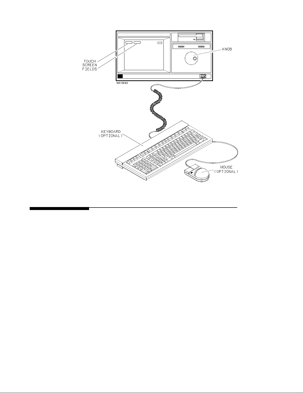
Figure 1-1. HP 16500A/16501A User Interfaces.
Default
Configurations
When the instrument is powered up, pre-determined values are
automatically assigned to the different fields of the menus to configure the
instrument for basic measurements. This allows you to make a basic
measurement by turning on the instrument, connecting the probes, and
touching the Run field. Often only minor changes are needed for more
complex measurements.
What Is the HP 16500A/16501A Logic Analysis System?
1-3
Page 17

Storing Default
Configurations
The default configurations may be stored on a disk for later use or reset by
cycling the power. Storing the default configurations on a disk is a
convenient way to return to the default values without cycling the power.
Default values for each module can be stored separately or together in one
file. Refer to Chapter 8 for more information on storing configurations.
What Is the HP16500A/16501A Logic Analysis System?
1-4
Page 18
2
Learning to Use the HP 16500A/16501A
This chapter introduces you to the HP 16500A/16501A user interfaces and
shows you how easy they are to use. Then it guides you through a brief
exercise using the interfaces to perform some basic operations.
The Display The menu is the actual display that you see on screen. It lists information
about the system and gives you access to touchscreen fields for
configuring the system. These fields give you access to additional fields,
allow you to move from menu to menu, input information, and perform
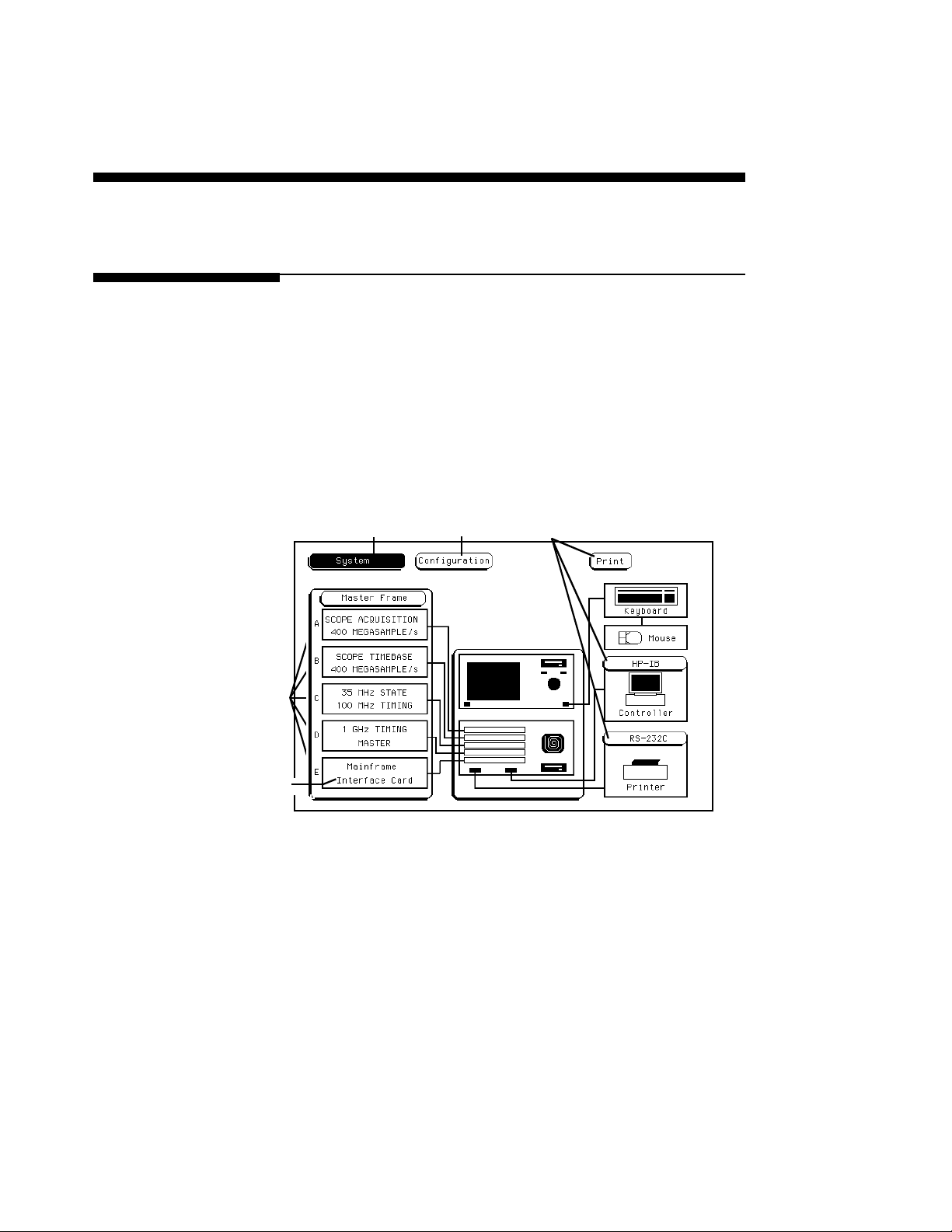
functions. Figure 2-1 points out some of the touchscreenfields and
information listed on the System Configuration menu for the HP 16500A.
Figure 2-2 shows the System Configuration menu for the HP 16501A
which shows the additional modules available through the expansion
mainframe.
Additional
ModuleField
Menu Field
Touchscreen
Fields
Slot
Designators
System Measurement Cards
Figure 2-1. The System Configuration Menu for the HP
16500A.
Learning to Use the HP 16500A/16501A
2-1
Page 19
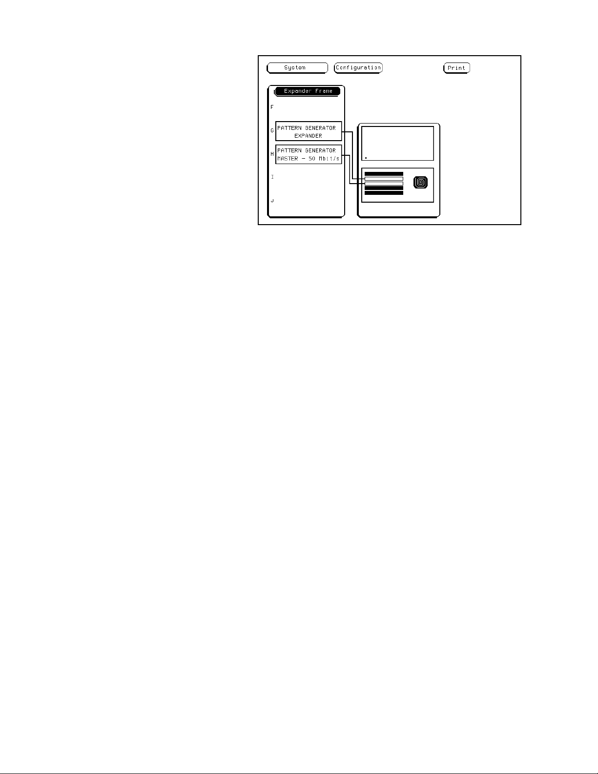
Figure 2-2. The System Configuration Menu for the
HP 16501A.
The Module field in the upper-left corner of the display represents the
hardware and system softwarethatformsa complete tool or software
option within the HP 16500A/16501A. The Menu field to the right of the
Module field represents one of the many screens available for configuring
individual modules.
The System Measurement Cards showninfigure2-1andfigure2-2
represent the individual modules installed within this HP
16500A/16501A. The Slot Designators listed to the left of the cards
show the physical location for each card within the HP 16500A/16501A.
In figure 2-1, the HP 16531A Oscilloscope Acquisition card is shown in
slot C and the HP 16530A Oscilloscope Timebase card is shown in slot D.
The combination of thesetwo cardsand the appropriate software
represents the 400 Megasample/Second Oscilloscope module in this HP
16500A/16501A.
Learning to Use the HP 16500A/16501A
2-2
Page 20
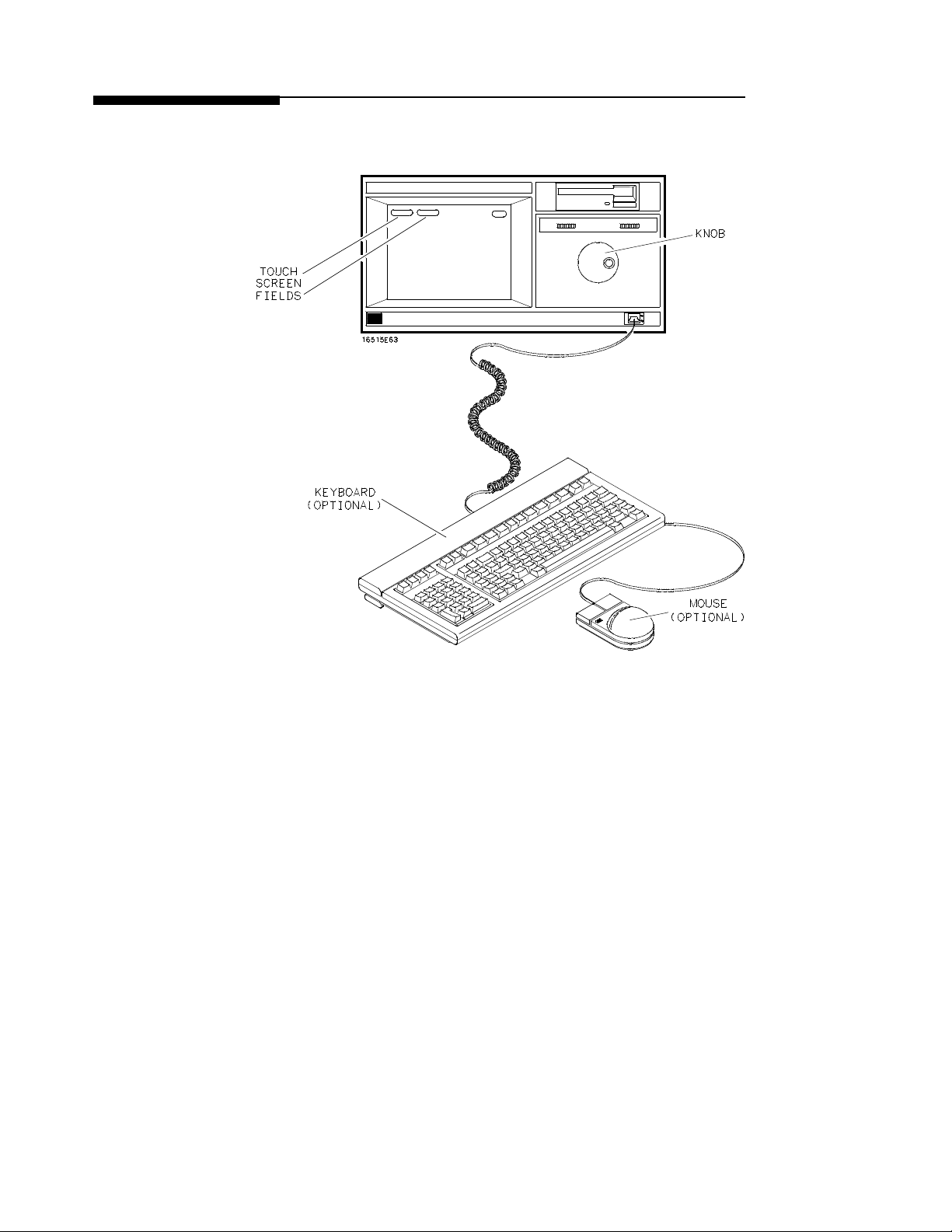
User Interfaces The HP 16500A/16501A has four user interface devices: the touchscreen,
the knob on the front panel, the optional mouse, and the optional keyboard.
Figure 2-3. User Interfaces.
Learning to Use the HP 16500A/16501A
2-3
Page 21

The
Touchscreen
Note
The touchscreen provides the main front-panel control or access to the
menus. It consists of touch-sensitive fields that you can use to enter
alphanumeric data into fields, access other menus, and configure the HP
16500A/16501A for measurements. Generally, any touch-sensitive field
orboxthatisusedtoaccessorenterinformationintheHP
16500A/16501A system is referred to as a field. The only exception is the
alphanumeric input fields in the pop-up keypads. These are referred to as
keys.
These fields can be selected using touch or the optional mouse or
keyboard. To activate a field by touch, touch or press the field (the blue
box) on the display with your finger until the field changes color. Then
move your finger away from the screen to activate your selection. If you
have trouble selecting the field you want, place your finger on the screen
and move it around and over that field until it changes color. Then move
your finger away from the screen.
No selection can be activated as long as your finger is touching the screen.
The only exception is keypads. Keypad selections are activated as you
touch them.
Types of Fields The touchscreen consists of a variety of different types of fields. These
fields may access pop-up menus, multiple-choice listings, keypads, etc.
Through these fieldsyou execute functions, move between menus, and
configure the system for specific operations.
Learning to Use the HP 16500A/16501A
2-4
Page 22
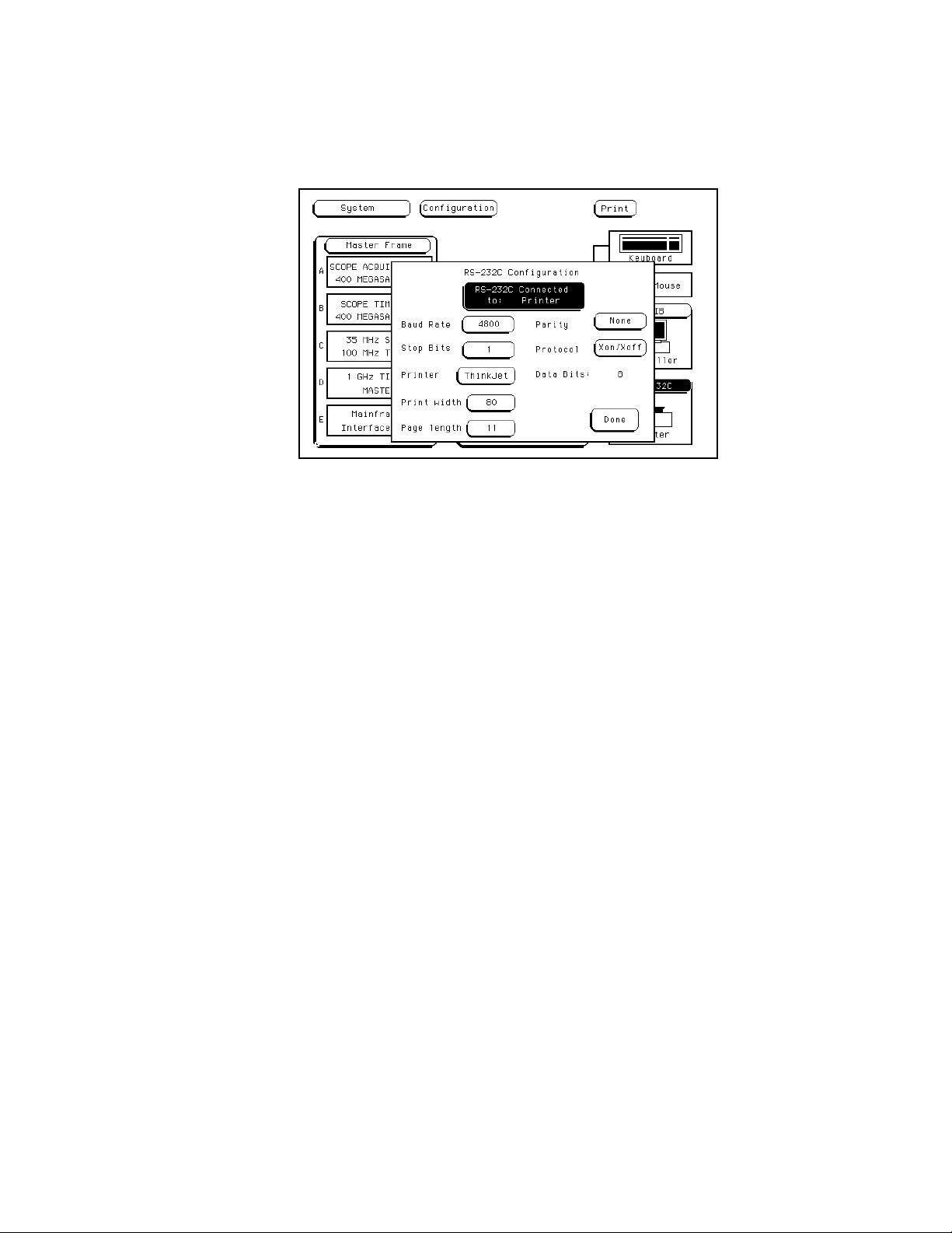
Pop-Up Menus Pop-up menus appear when you touch certain fields. They display the
functions available for configuring or performing major operations,
including configuring the RS-232C interface, calibrating the touchscreen,
and more. When you are finished with the pop-up menu, simply touch
Done to return to the original display.
Figure 2-4. The RS-232C Pop-Up Menu.
Learning to Use the HP 16500A/16501A
2-5
Page 23
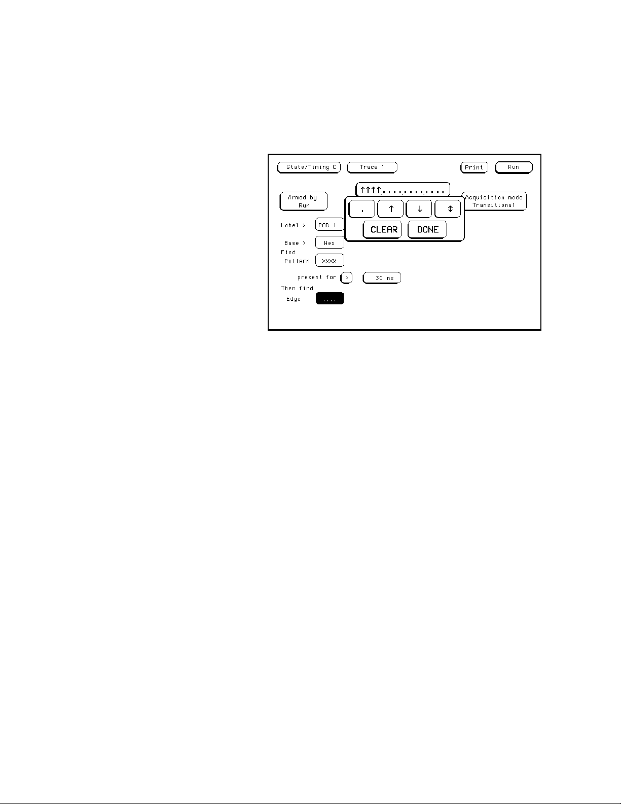
Pattern Fields Pattern fields are fields that access pop-up menus that only display
selections available for a single function. A good example of this is the
Edge field of the Trace menu of the logic analyzer. The selections
available apply only to the Edge field. As you make your selections,the
selectionsappear in a box at the top of the pop-up menu. When you are
finished configuring the pattern field, touching Done returns you to the
original display and updates the pattern field with the new configuration.
Figure 2-5. The Edge Field Pop-Up Menu.
Learning to Use the HP 16500A/16501A
2-6
Page 24
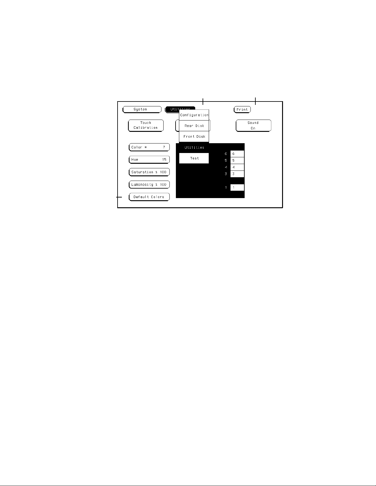
Multiple-Choice
Listings
Multiple-choice listings display the selections available for particular
operations, menus available for particular modules, modules available
within particular mainframes, and more. By selecting the appropriate
fields you can configure operations, change menus,move between
modules, etc. To return to the original selection, touch the field within the
listing that has the light-blue background.
Multiple-Choice Listings
Immediate-Action Field
Figure 2-6. Multiple-Choice Menus and Toggle Fields.
Toggle Fields Toggle fieldshave only two possible entries. They switch between
functions (such as from a Controller to a Printer configuration) or simply
turn a feature on and off. To return to the original selection, simply touch
the field again.
Toggle Field
Learning to Use the HP 16500A/16501A
2-7
Page 25
Immediate-Action
Fields
Immediate-action fields perform a function as soon as they are selected.
For example, selecting the Done field immediately returns you to the
original display. Selecting the Default Colors field immediately returns
you to the default display colors. There are no additional selections or
actions required.
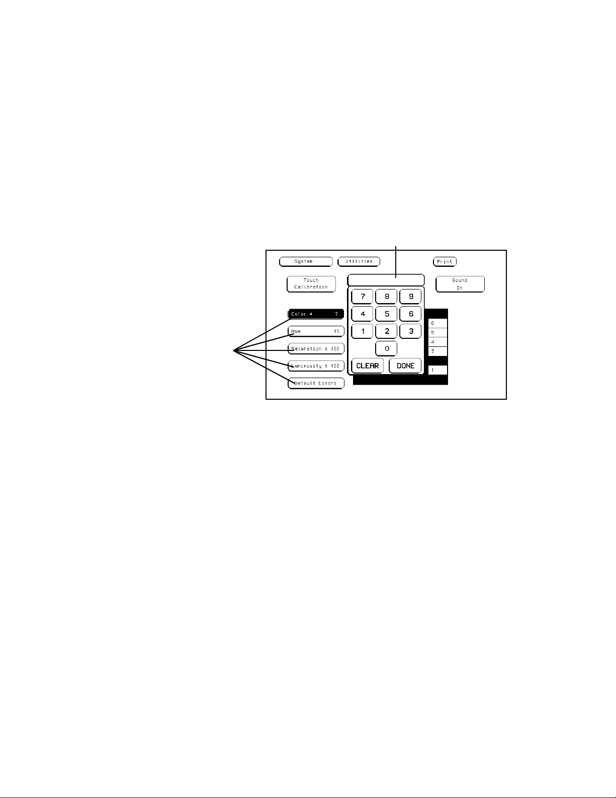
Knob/Numeric
Fields
Numeric Fields
If a numeric field isn’t light blue, touching the field once turns it light
blue. Once a field is light blue, rotating the knob changes the value in it.
If you touch a numeric field that is already light blue, a keypad appears on
screen to enter a new value.
Once the value for a numeric field has been changed, you can return to the
original value by entering it with the keypad or by rotating the knob.
Numeric Keypad
Figure 2-7. Numeric Fields.
Learning to Use the HP 16500A/16501A
2-8
Page 26
Alphanumeric
Keypads
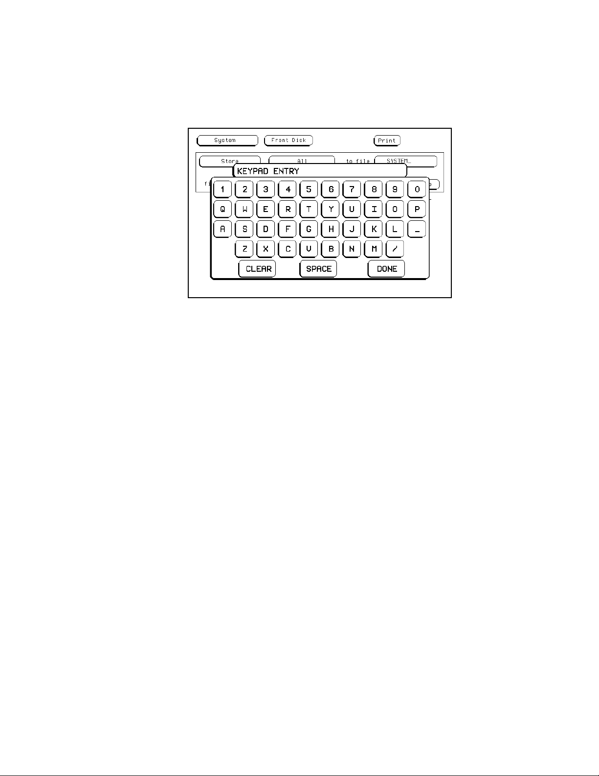
When you select a field that requires an alphanumeric input, an
alphanumeric keypad appears on screen. Simplyenter the appropriate
information with the keypad and touch Done when you are finished.
To return to the original information after an alphanumeric field has been
changed, re-enter the original information with the keypad.
Figure 2-8. Alphanumeric Keypad.
Entering
Information with
the Keypad
To enter information with the keypad, simply touch the appropriate key
for each input and that input will appear in the box at the top of the
keypad. When you are finished, touch Done and the keypad disappears,
placing your entry in the appropriate field.
If you need to change a letter or correct a mistake for a pattern or
alphanumeric entry before leaving the keypad, simply move the cursor
with the knob to the character you want to change and enter the correct
character.
Generally, to return to the original value before completing an entry, touch
Clear,thenDone.
Learning to Use the HP 16500A/16501A
2-9
Page 27
The Optional
Mouse
The optional mouse is a mechanical device that you can move about on a
desktop to controla pointer (+) on the menu. When the pointeris on the
desired field, select that field by pressing the button on the upper-left
corner of the mouse.
You can also use the mouse to duplicate the function of the knob on the
front panel. Simply hold down the button on the upper-right corner of the
mouse and move the mouse about on a desktop. Moving the mouse up or
to the right is the same as turning the knob clockwise. Moving the mouse
down or to the left is the same as turning the knob counterclockwise.
Connecting the
Mouse
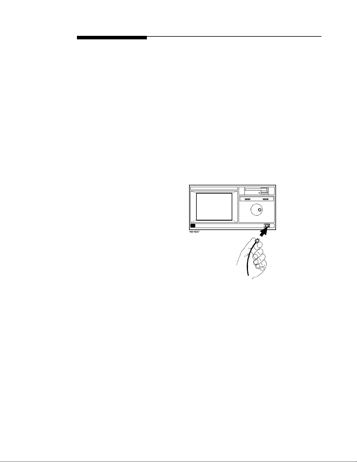
To connect the mouse:
1. Hold the connector (on the cord of the mouse) with the two spring
clips on the bottom.
2. On the lower-right corner of the HP 16500A front panel is a port
marked with two dots. Gently push the connector into this port until
the connector clicks into place.
Figure 2-9. Connecting the Optional Mouse.
Learning to Use the HP 16500A/16501A
2-10
Page 28
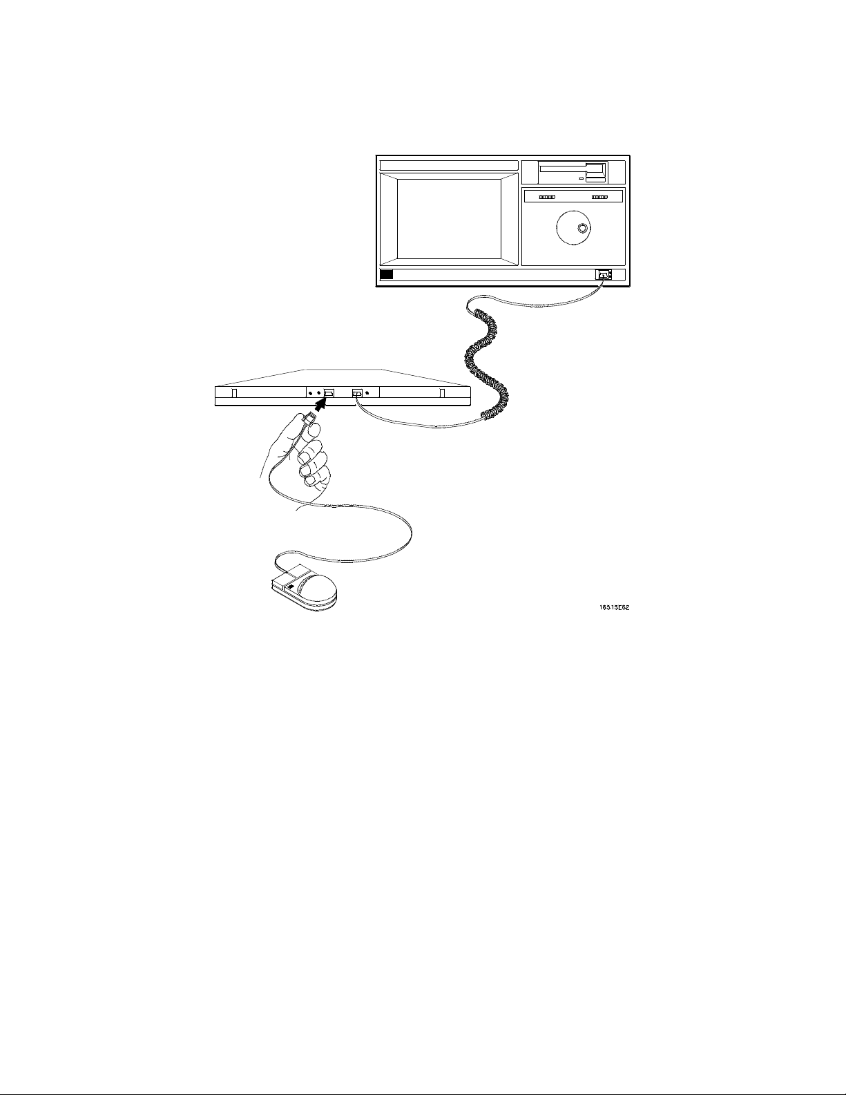
The mouse may also be plugged into the optional keyboard interface (HP
E2427A Keyboard Kit). To connect the mouse to the keyboard, insert the
connector end of the mouse (marked with two dots) into the port marked
with two dots located on the back of the keyboard.
Figure 2-10. Connecting the Mouse to the Optional Keyboard.
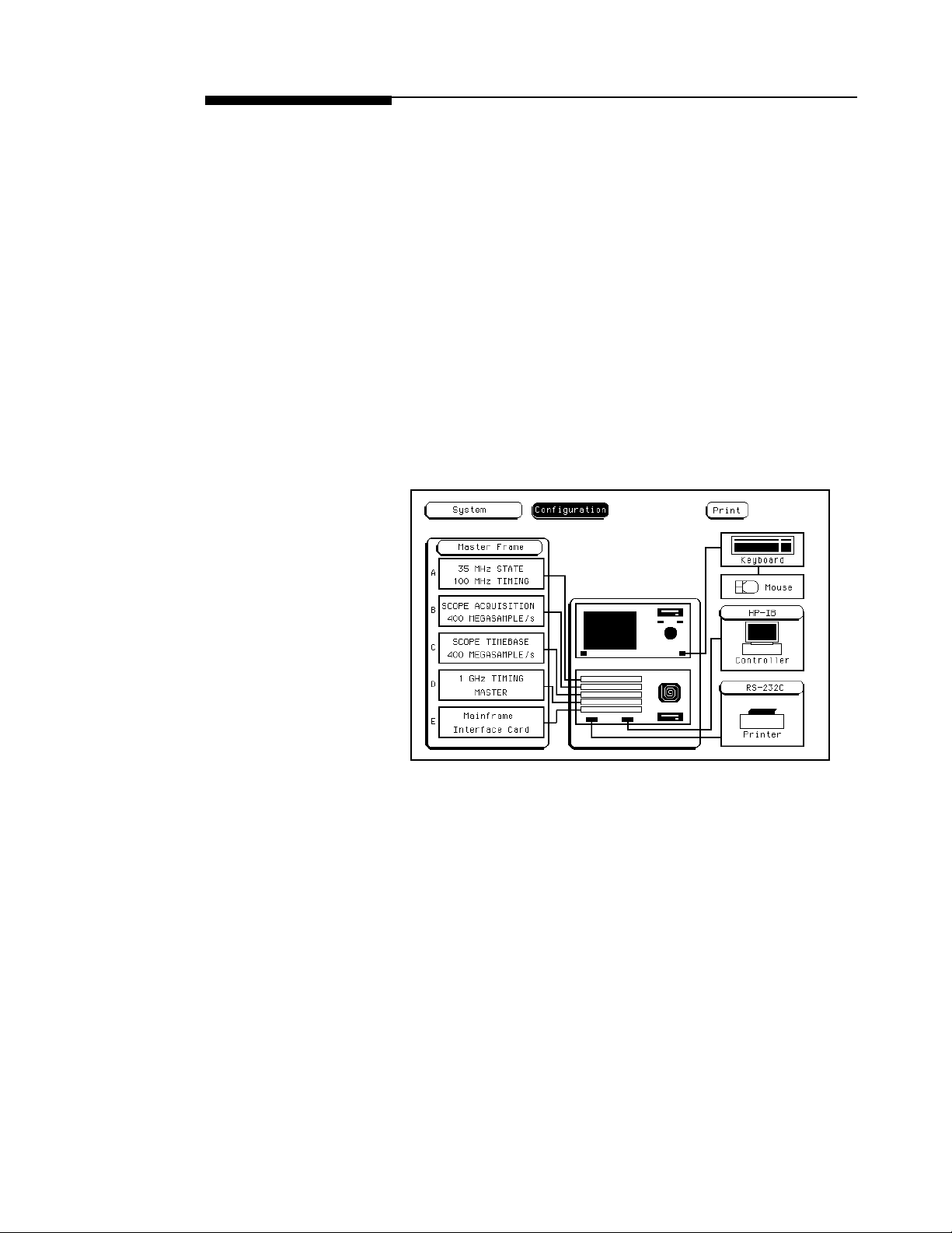
When the mouse is connected directly to the HP 16500A mainframe, the
System Configuration menu will show a mouse icon connected to the
instrument (see figure 2-11).
Learning to Use the HP 16500A/16501A
2-11
Page 29
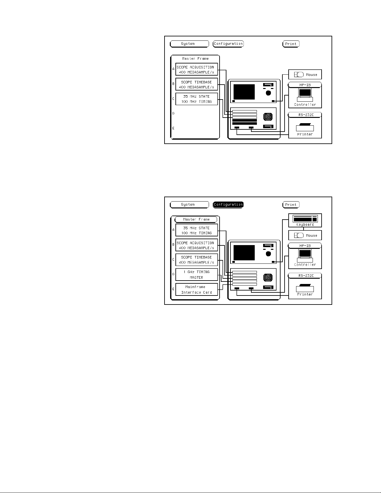
Figure 2-11. System Configuration Menu With the
Mouse Only.
When the mouse is connected to the keyboard,the System Configuration
menu will display a picture of the mouse connected to the keyboard,
which is in turn connected to the HP 16500A mainframe (see figure 2-12)
Figure 2-12. System Configuration Menu With the
Mouse Connected Through the Keyboard.
Learning to Use the HP 16500A/16501A
2-12
Page 30

Disconnecting the
Mouse
To disconnect the mouse, press the two spring clips on the connector
together and gently pull the connector out of the port.
The Optional
Keyboard
Connecting the
Keyboard
To select a field using the optional keyboard, position the keyboard cursor
(the location highlighted in inverse video) on the desired field and press
either the Return or Select key.
You can also use the keyboard to duplicate the function of the knob on the
front panel of the HP 16500A. The keyboard uses the shift and cursor
keys to simulate knob spin. To simulate rotating the knob clockwise,
simultaneously press the Shift key and either the up-pointing arrow key or
the right-pointing arrow key. To simulate rotating the knob
counter-clockwise, simultaneously press the Shift key and either the
down-pointing arrow key or the left-pointing arrow key.
For more information on keyboard functions, pleasesee Chapter 3.
To connect the keyboard:
1. Hold the connector with the two spring clips facing down.
2. Gently push the connector into the port on the front panel until it
clicks into place.
Learning to Use the HP 16500A/16501A
2-13
Page 31
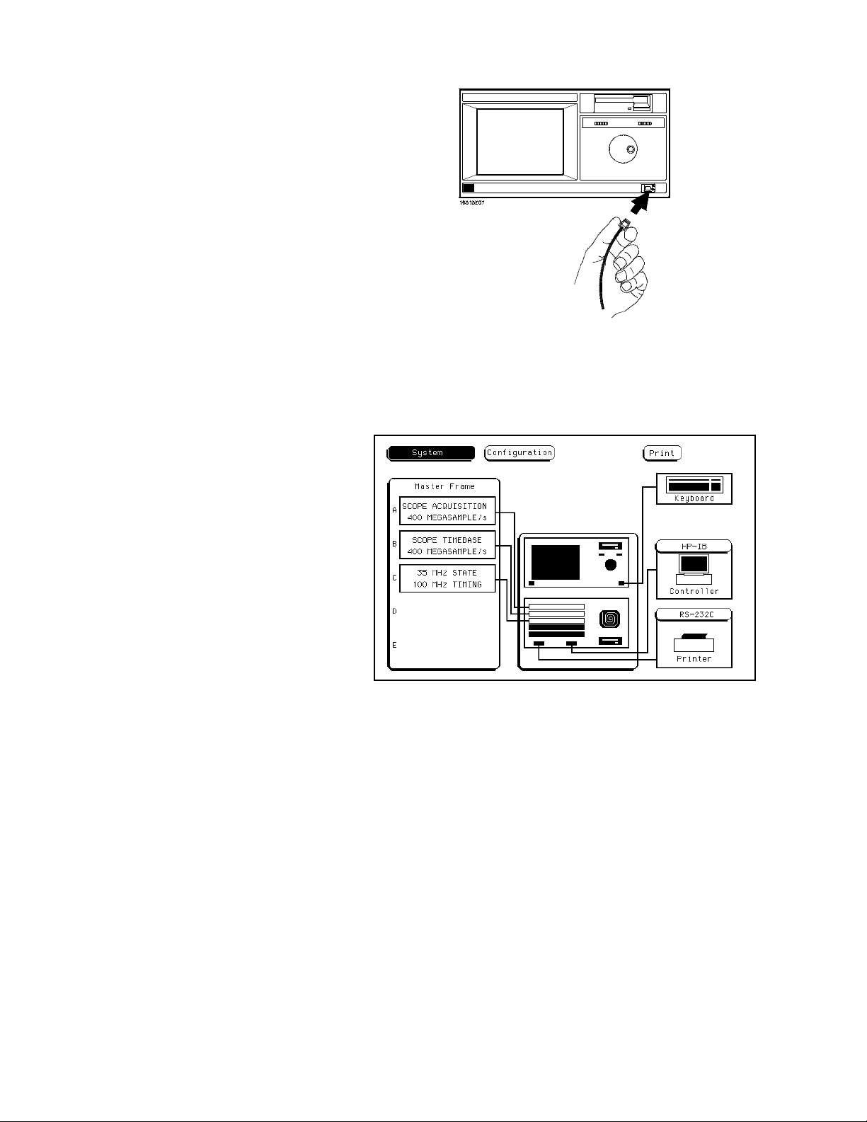
Figure 2-13. Connecting the Optional Keyboard.
When the keyboard is connected to the HP 16500A, the System
Configuration menu will display the connection as a picture showing the
keyboard connected to the mainframe.
Figure 2-14. System Configuration Menu with the
Keyboard.
Learning to Use the HP 16500A/16501A
2-14
Page 32
Disconnecting the
Keyboard
To disconnect the keyboard, press the two spring clips on the connector
together and gently pull the connector out of the port.
The Knob The knob on the front panel can move the cursor on certain menus,
increment and decrement numeric fields, and roll the display. “Rolling the
display” refers to the instrument’s ability to rotate or scroll through
information on the screen.
The Cursor The cursor is a position indicator in the display that allows you to
highlight characters within fields and other areas within certain menus.
Rotating the knob moves the cursor within a particular field or function or
moves the cursor through information line by line. The location of the
cursor is displayed in inverse video.
Cursors
Figure 2-15. Cursor Examples.
Learning to Use the HP 16500A/16501A
2-15
Page 33
Exercises The following brief exercises will help you become more familiar with
using the HP 16500A/16501A interfaces. The steps are both numbered
and lettered. The numbered steps state the objective and the lettered steps
explain how to accomplish each step objective. You may be able to go
through the exercises by just following the numbered steps. When you
need more information on how to accomplish the step objective, refer to
the lettered steps.
1. Make sure you are in the System Configuration menu. If not,
select this menu.
a. If you are not already in the System module, as indicated by the
field in the upper-left corner of the menu, touch this field. When the
(multiple-choice) pop-up appears, touch System and the pop-up
disappears,bringing up one of the System menus.
b. If you are not already in the Configuration menu, as indicated by
the field to the right of System, touch this field. When the pop-up
appears, touch Configuration and the pop-up disappears, bringing
up the System Configuration menu.
Figure 2-16. The System Configuration Menu.
Learning to Use the HP 16500A/16501A
2-16
Page 34
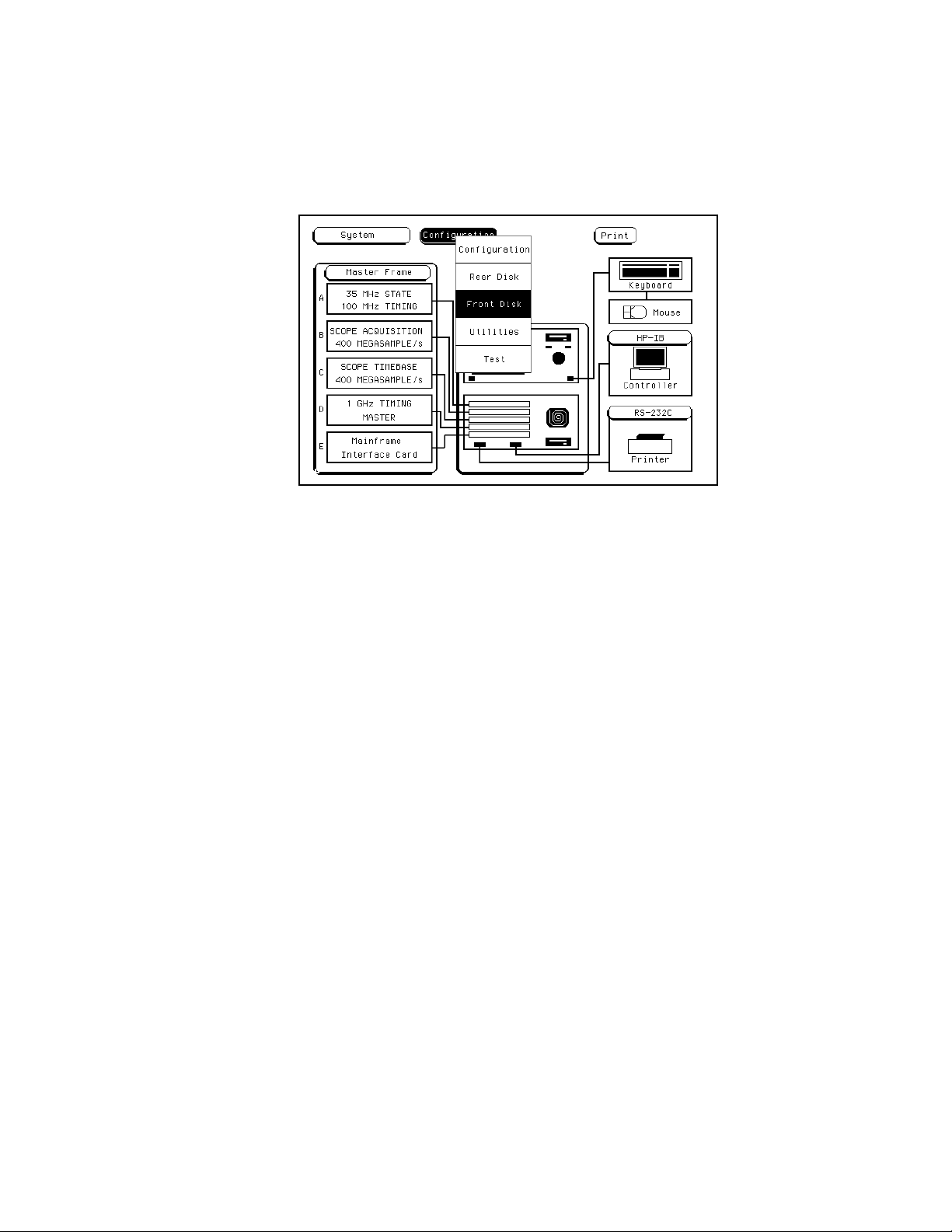
2. Select the System Front Disk menu.
a. Touch the menu fieldto the right of System in the upper-left corner
of the display.
b. When the (multiple-choice) pop-up appears, touch Front Disk and
the pop-up disappears, bringing up the System Front Disk menu.
Figure 2-17. Selecting the System Front Disk Menu.
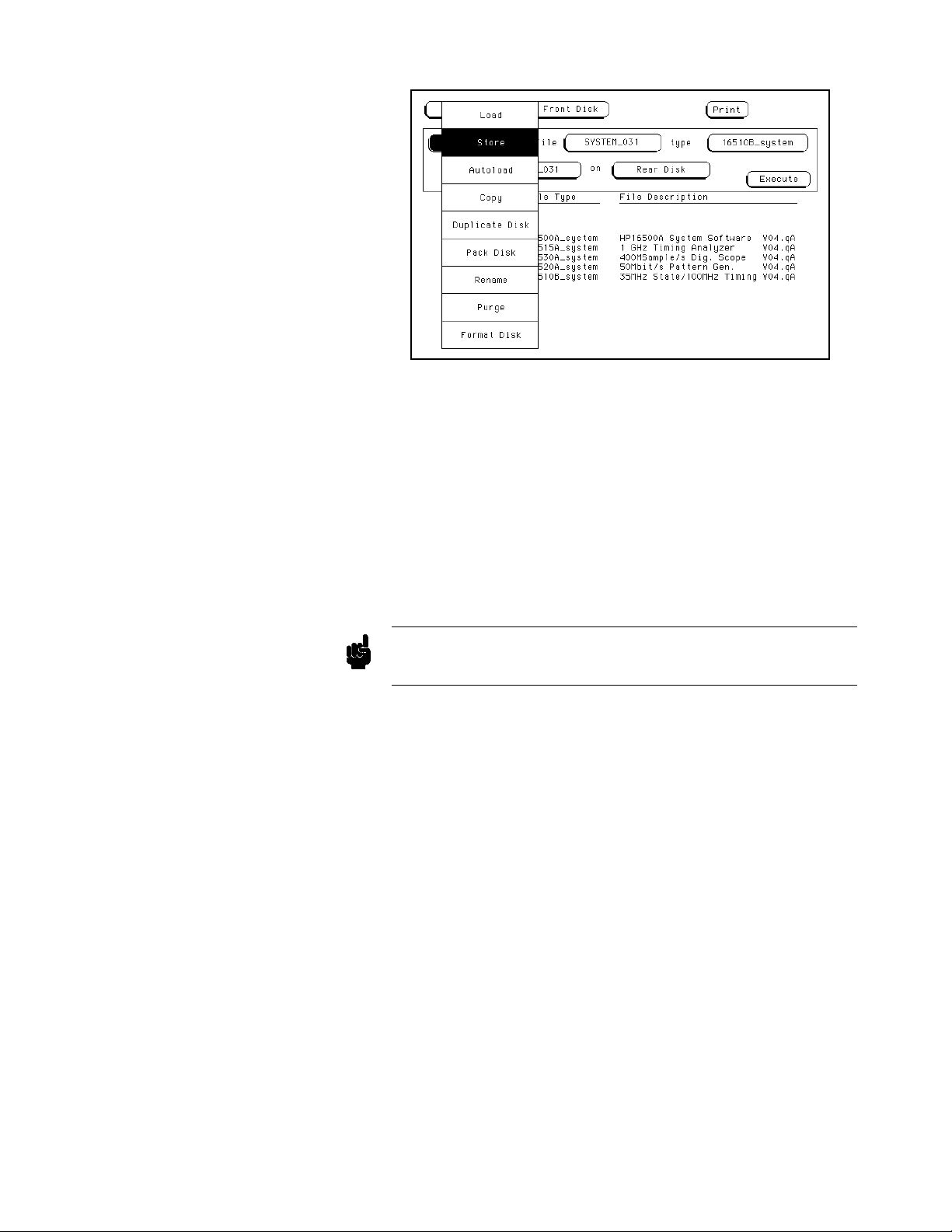
3. Select the Store operation.
a. Select the file operation field directly below the module field by
touch, mouse, or keyboard.
b. When the pop-up appears, select Store. This brings up the Store
operation.
Learning to Use the HP 16500A/16501A
2-17
Page 35
Note
Figure 2-18. Selecting the Store Operation.
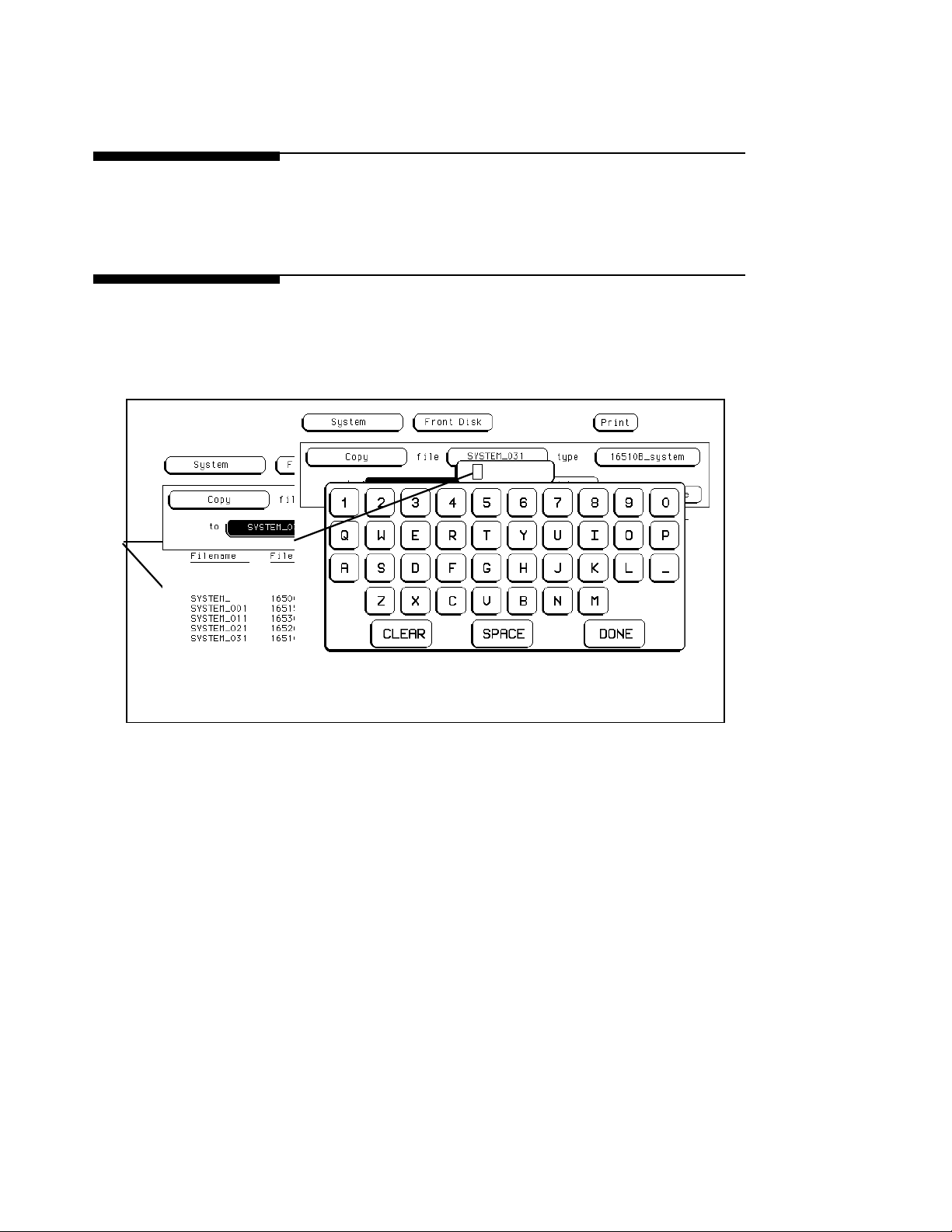
4. Enter the filename “EXAMPLE1" in the field to the right of ”to file."
a. Touch the filename field to the right of “to file” or select it using the
optional mouse or keyboard.
b. When the pop-up alphanumeric keypad appears, enter
“EXAMPLE1" with the keypad by touching the appropriate key for
each character or keying in the information using the optional
keyboard. As you enter each character, the character appears in the
box at the top of the keypad and the cursor moves one space to the
right.
To change a letter or correct a mistake, use the knob to move the cursor to
the letter you want to change and enter the correct letter.
c. When you are finished, select Done by touch, mouse, or keyboard
and the pop-up disappears, putting EXAMPLE1 in the appropriate
field.
Learning to Use the HP 16500A/16501A
2-18
Page 36
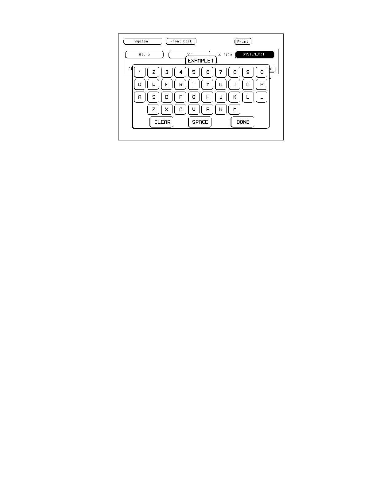
Figure 2-19. Entering a Filename.
5. Enter “CONFIGURATIONS AND DATA” for the file description.
a. Touch the field to the right of “file description”, or select it using the
optional mouse or keyboard.
b. When the pop-up alphanumeric keypad appears, enter
“CONFIGURATIONS AND DATA” in the box with the keypad by
touching the key for each letter or by keying in the information
using the optional keyboard.
c. When you are finished, select Done by touch, mouse, or keyboard
and the pop-up disappears, putting “CONFIGURATIONS AND
DATA” in the appropriate field.
Learning to Use the HP 16500A/16501A
2-19
Page 37
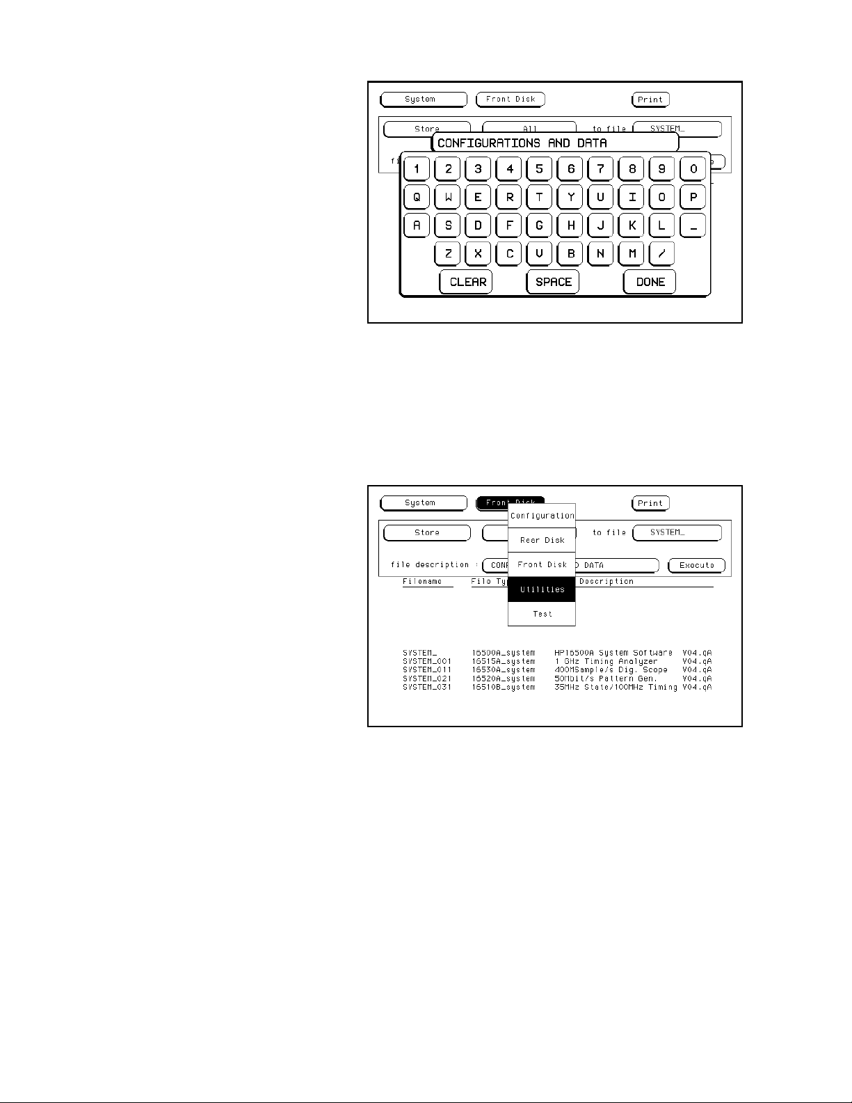
Figure 2-20. Entering a File Description.
6. Now select the System Utilities menu.
a. Select the menu field to the right of System in the upper-left corner
of the display using touch, the mouse or the keyboard.
b. When the pop-up appears, select Utilities and the pop-up
disappears, bringing up the System Utilities menu.
Figure 2-21. Selecting the System Utilities Menu.
Learning to Use the HP 16500A/16501A
2-20
Page 38
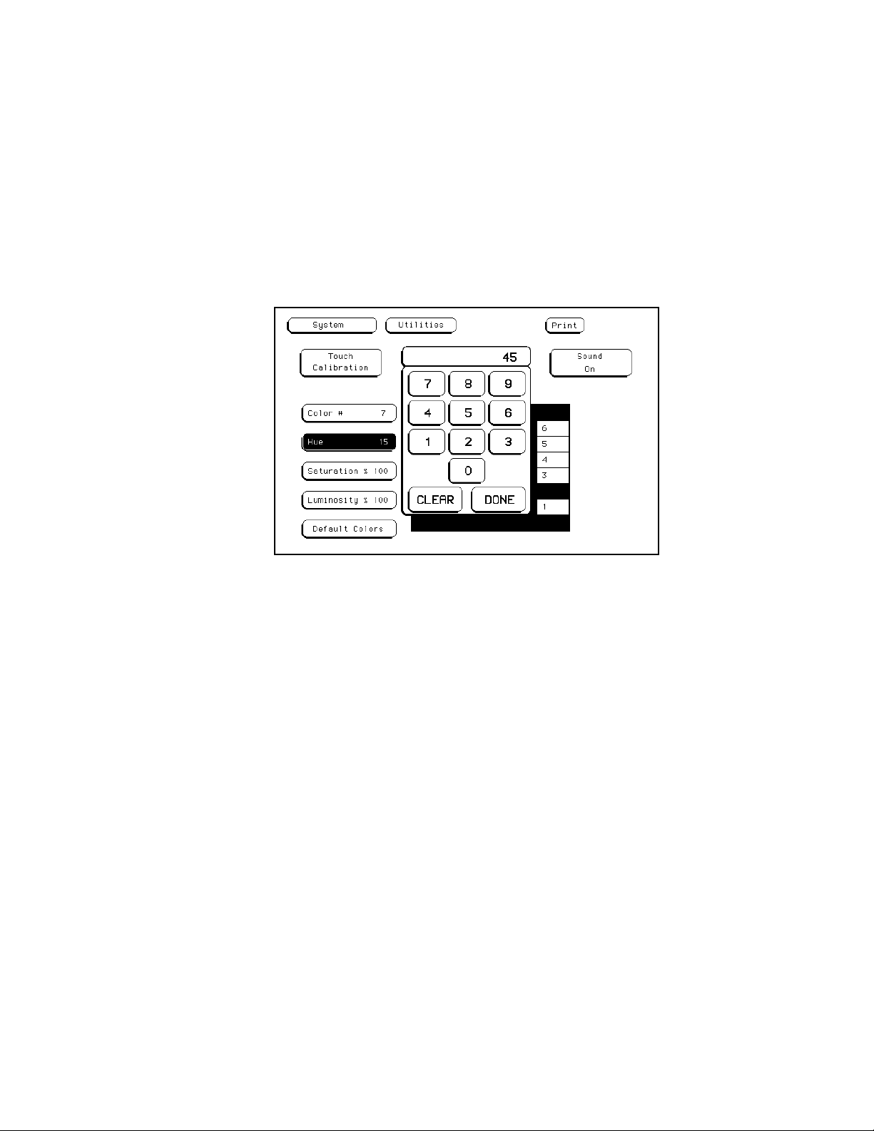
7. Change theHuefor Color#5 to 45 with the keypad.
a. If the Color field isn’t light blue, touch this field.
b. Rotatetheknobcounterclockwise (or simulate knob rotation using
the optional mouse or keyboard) until 5 appears in the Color field.
c. Touch the Hue field below the Color field.
d. After it turns light blue, select the Hue field again and a pop-up
keypad appears.
e. Enter 45 with the keypad or optional keyboard and select Done.
The keypad will disappear, putting 45 in the Hue field.
Figure 2-22. Entering a New Value for Hue.
8. Return to the default settings for the color fields.
a. Select the Default Colors field in the lower-left corner of the menu.
Since this is an immediate action field, selecting the Default Colors
field immediately returns you to the default display colors.
Learning to Use the HP 16500A/16501A
2-21
Page 39
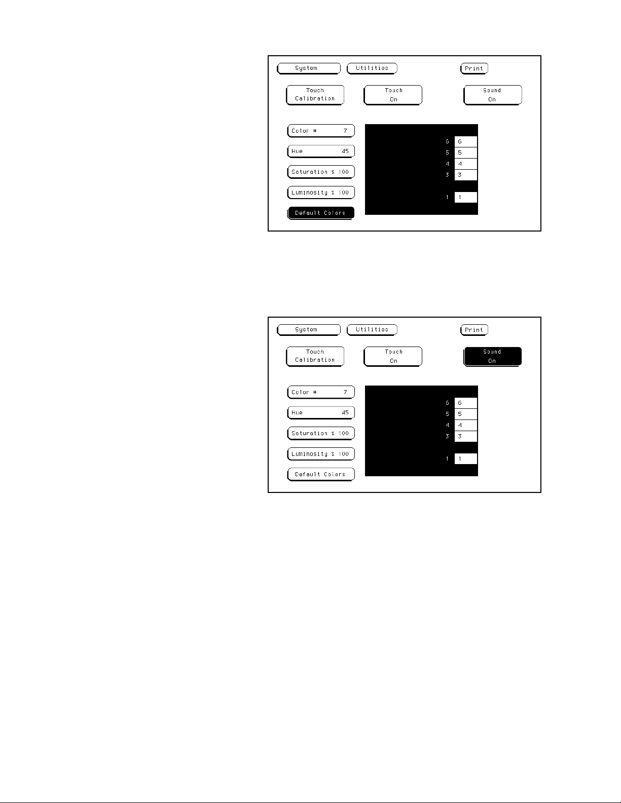
Figure 2-23. Returning to the Default Colors.
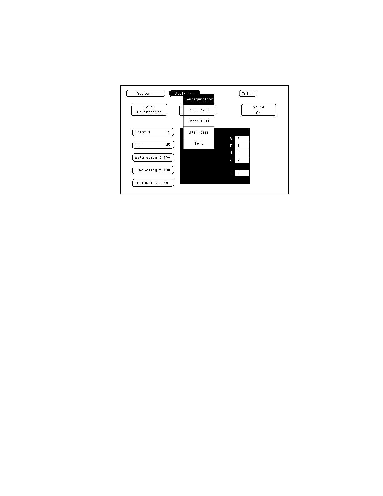
9. Turn off the sound of the instrument.
a. Select the Sound On field and it toggles to Sound Off.
Figure 2-24. Turning the Sound Off.
10. Then turn the sound back on.
a. Select the Sound Off field and it toggles to Sound On.
Learning to Use the HP 16500A/16501A
2-22
Page 40
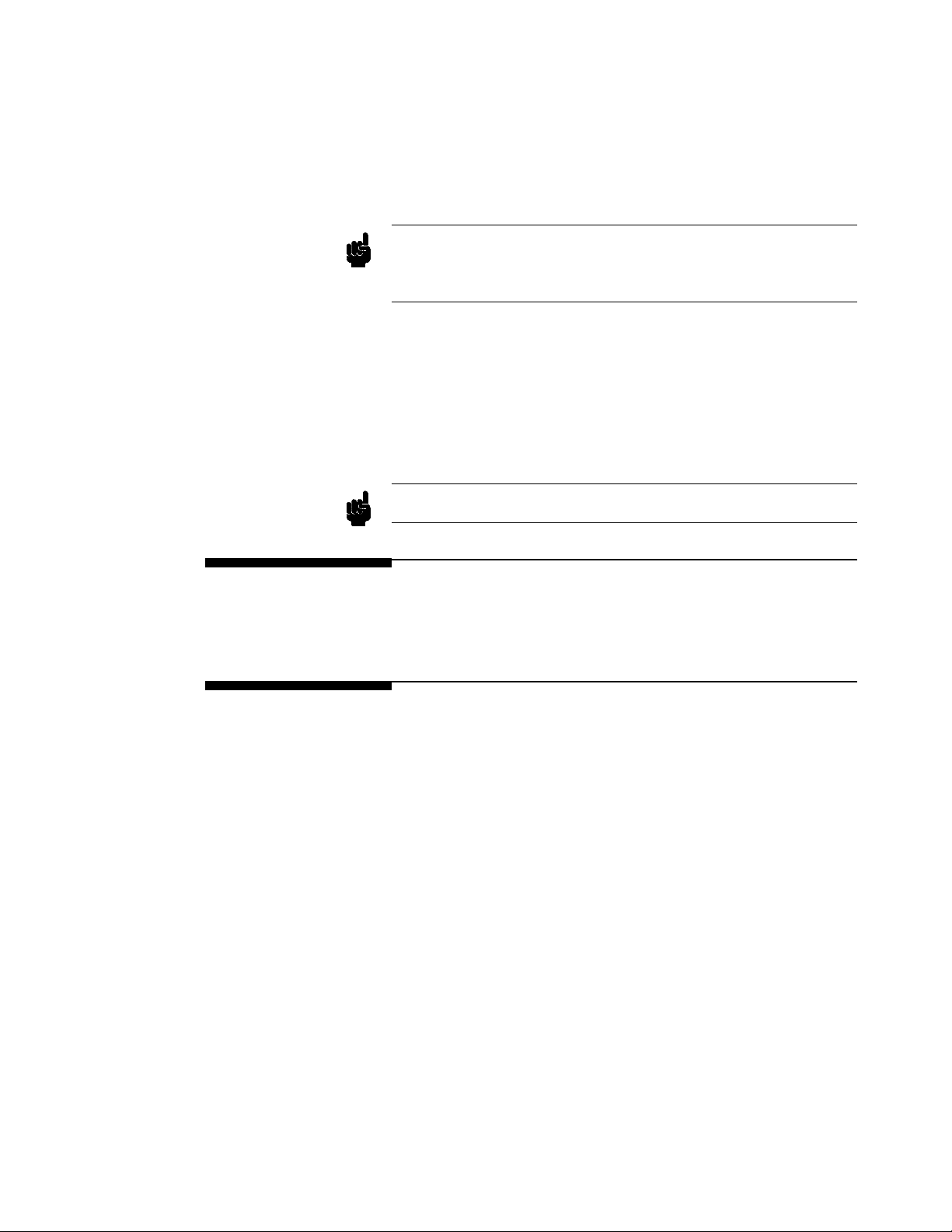
11. ReturntotheSystem Configuration menu.
a. Touch the menu fieldto the right of System in the upper-left corner
of the display.
b. When the pop-up appears, select the Configuration field. The
pop-up disappears, bringing up the System Configuration menu.
Figure 2-25. Selecting the System Configuration Menu.
Refer to specific chapters in this manual for more information on the
functions and menus of the HP 16500A/16501A.
Learning to Use the HP 16500A/16501A
2-23
Page 41

Using the Optional Keyboard Interface
This chapter explains how to use the optional keyboard interface (HP
E2427A Keyboard Kit) with the HP 16500A/16501A. The keyboard can
be used interchangeably with the knob, touchscreen, and the mouse for all
menu applications. The keyboard functions fall into two basic categories:
cursor movement and data entry:
3
Moving the
Cursor
Cursor Keys There are four cursor keys marked with arrows on the keyboard. These
Tab Key Another way to move the keyboard cursor is to use the Tab key. The Tab
The keyboard cursor is the location on the screen highlighted in inverse
video. To move the cursor, follow one of the methods described below.
keys perform the followingmovements:
• Up-pointing arrow - moves the cursor up.
• Down-pointing arrow - moves the cursor down.
• Right-pointing arrow - moves the cursor to the right.
• Left-pointing arrow - moves the cursor to the left.
The cursor keys do not wrap. This meansthat pressing the right-pointing
arrow when the cursor is already at the rightmost point in a menu will
have no effect. The cursor keys do repeat, so holding the key down is the
fastest way to continue keyboard cursor movement in a given direction.
You can also use the cursor keys to duplicate the function of the knob on
the front panel of the HP 16500A. To simulate rotating the knob
clockwise, simultaneously press the Shift key and either the up-pointing
arrow key or the right-pointing arrow key. To simulate rotating the knob
counter-clockwise, simultaneously press the Shift key and either the
down-pointing arrow key or the left-pointing arrow key.
key wraps and repeats. You can scroll through all the choices in a given
menu by pressing and holding down the Tab key. The Tab key moves the
Using the Optional Keyboard Interface
3-1
Page 42
keyboard cursor fromleft to right, and, upon reaching the right margin of
a line, causes the cursor to move to the left margin of the next line and
continue its left-to-right motion.
If you want to want to move in the opposite direction, from right to left,
moving up to the next higher line when the left margin is reached, press
andholdboththeTabkeyandtheShiftkeysimultaneously.
Neither the Tab key nor the Tab and Shift key combination will work in
Note
scroll-type pop-up menus. Use the cursor keys to make selections in these
menus.
Home Key If you want to move the cursor to the first item in a menu, press the Home
key. If you want to move the cursor to the last item in a menu, press the
Home and Shift keys simultaneously.
Next and Previous
Keys
Note
Selecting a
Menu Item
Entering Data
into a Menu
The Next and Previous keys are used for paging through listings. The
Next key will display the next page of data, if one exists. The Previous
key will display the previous page of data, if one exists.
These functionswork only for the HP 16510A/B Logic Analyzer modules.
To select a menu item using the optional keyboard, position the cursor
(the location highlighted in inverse video) on the desired menu item using
one of the methods described in the section “Moving the Cursor” and
press either the Return or the Select key.
When the cursor is over the desired field, and either the Return key or the
Select key is pressed, the cursor is displayed over the leftmost digit of the
particular item. When you enter a number, it is displayed in the cursor
position, and the cursor is advanced. Cursor keys move the cursor within
the field. Pressing either the Return key or the Enter key will terminate
data entry for that item.
Using the Optional Keyboard Interface
3-2
Page 43

If you want to erase the data entry, press the Clear Line key, the Clear
Display key, or the Delete Line key.
Autoroll When entering pattern generator data, you can move through each line
horizontally, filling in each data field in the line before going to the next
line, or you may want to fill in all the data in a column before moving on
to the next column. The Autoroll feature makes moving from one data
entry field to another easier than selecting each in succession.
When you select a data field and the pop-up appears, notice that a field
labeled Autoroll also appears at the left side of the screen. To use the
Autoroll feature, place the cursor over the desired data field, then press
either the Return key or the Select key. When the cursor is at the left
margin of the data, press the left-pointing arrow key. The cursor will
disappear from the data and reappear in the Autoroll field.
When you select the Autoroll field, another pop-up appears. This pop-up
presents you with three choices:
• Off.
• A field containing a right-pointing arrow and a down-pointing arrow.
• A field containing a down-pointing arrow.
If you want to move through your data line by line, from left to right,
select the field marked with the right-pointing arrow and the
down-pointing arrow. Once this field is activated, the pop-up will close
and autoroll throughthedata fields from left to right. When you finish
entering data into the last field in a line, the pattern generator will
automatically move to the first field in the next line. This process
continues until the pattern generator reaches the end of the program or
until you turn the Autoroll off.
If you want to move through your data column by column, select the
pop-up field marked with the down-pointing arrow. When this field is
selected, the patterngenerator moves down each column of data, and,
when data entry in the column is complete, automatically moves to the top
of the next column. This process continues until the end of the program is
reached or until you turn the Autoroll off.
Using the Optional Keyboard Interface
3-3
Page 44
Autoroll is automatically turned off when data entry to all the available
fields is complete. If you want to turn off the Autoroll before data has
been entered into all the data fields, press the left-pointing arrow key when
the cursor is at the left margin of a data field. When the Autorollpop-up
appears, select Off.
Using the
Keyboard
Overlays
The function keys above the number pad have been redefined to work
with the HP 16500A/16501A keypad. These function keys are listed in
table 3-1:
Table 3-1. Units and Hex Keys
Key Real-Time
Keypad
F9 Seconds Volts D
F10 Milliseconds Millivolts E
F11 Microseconds - F
F12 Nanoseconds - -
*- - A
/- - B
+- - C
Voltage
Keypad
Hex Keypad
Using the Optional Keyboard Interface
3-4
Page 45
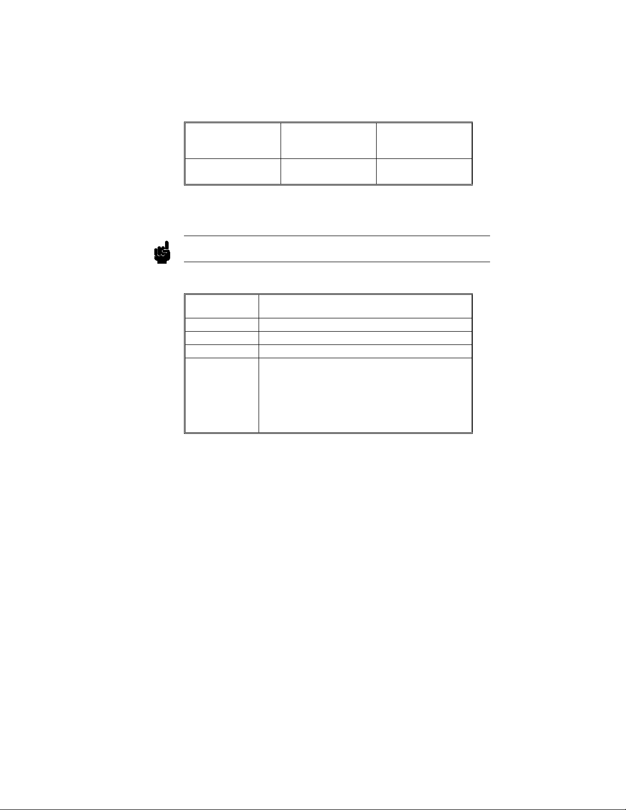
Don’t Care Key Tab is the “Don’t Care” key. The value of this key is determined by the
currently displayed keypad. It is “X” in the hex keypad and double quotes
("") in the stimulus hex keypad.
Table 3-2. Don’t Care Key
Key Stimulus Hex
Tab
("Don’t Care")
Double Quotes ("") X
Keypad
Hex Keypad
Function Keys Several function keys have been provided to simplify frequently used
keystrokes. Table 3-3 lists the functions mapped to these keys.
F1, F2, F7, and F8 only work when there are no submenus popped up.
Note
Table 3-3. Operation Function Keys
Key Function
F1 Selects and pops up the module field.
F2 Selects and pops up the menu field.
F7 Selects and pops up the print field.
F8 Invokes the run key for its current setting. If the
run key is set to repetitive, then pressing F8 will
invoke repetitive running. If the run key is set to
single run, then pressing F8 will invoke a single
run. Ifthe module is running, then F8 will stop
the module.
Using the Optional Keyboard Interface
3-5
Page 46

Defining Time
Units
In addition to the function keys which are mapped to the HP
16500A/16501A real-time keypad, other keys on the keyboard invoke the
units keys. The time unit keys are listed in Table 3-4.
Table3-4.TimeUnitsKeys
Key Time Units
S Selects the seconds units
M Selects the milliseconds units
U Selects the microseconds units
N Selects the nanoseconds units
Defining
Voltage Units
Besides the functionkeyswhicharemapped to the HP 16500A/16501A
real-time keypad and the time units keys, other keys on the keyboard
invoke the voltage units keys. The voltage unit keys are listed in Table
3-5.
Table 3-5. Voltage Units Keys
Key Voltage Units
V Selects volts
M Selects millivolts
Using the Optional Keyboard Interface
3-6
Page 47
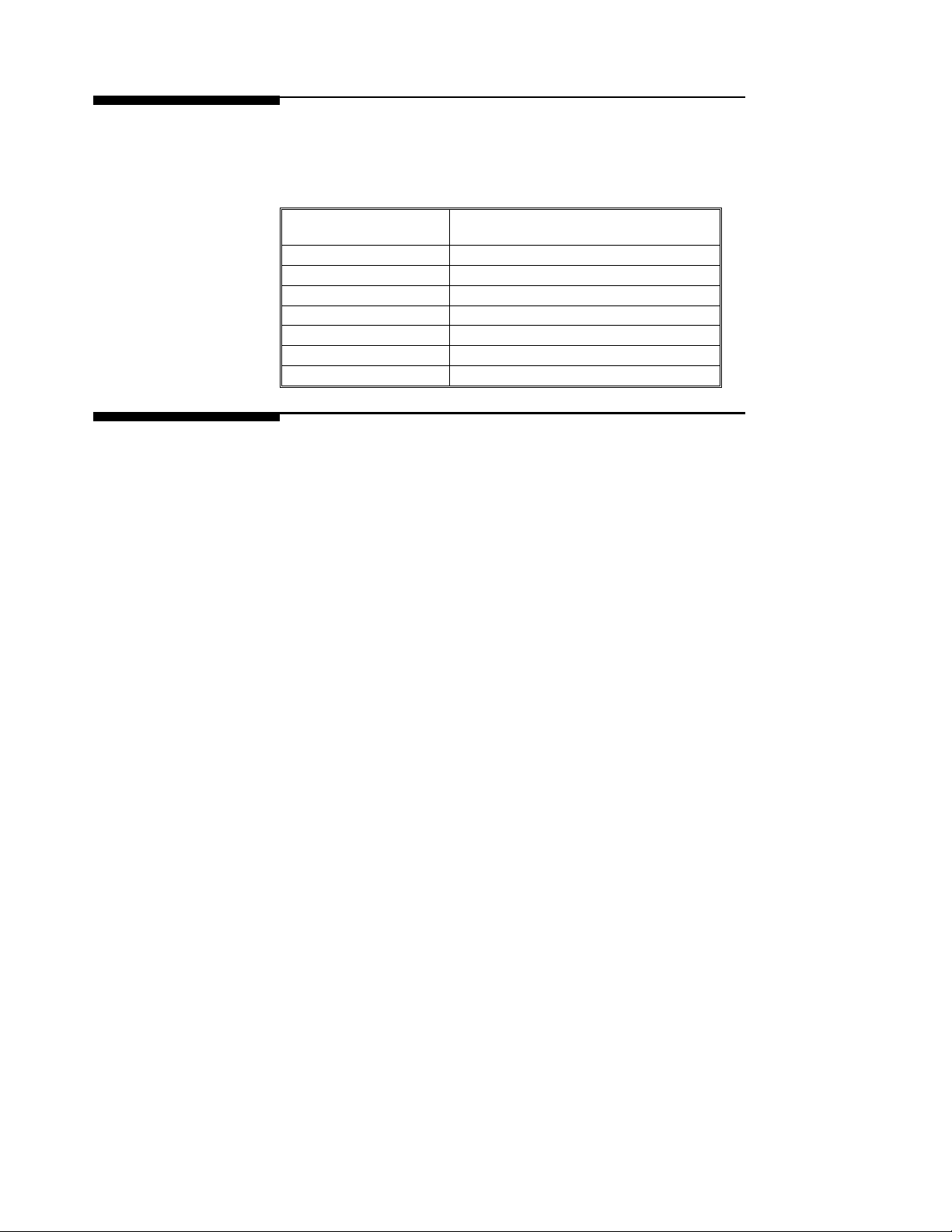
Assigning
Edge Triggers
Several keys map to edge assignments. These keys and their functions are
listed in Table 3-6.
Table 3-6. Edge Trigger Keys
Key Edge Trigger Assignment
U Selects the up or rising edge.
D Selects the down or falling edge.
R Selects the rising edge.
F Selects the falling edge.
B Selects either the rising or falling edge.
Up-Pointing Arrow Selects the rising edge.
Down-Pointing Arrow Selects the falling edge.
Closing a Menu To exit a menu, press either the Done or Enter key. TheEnter key is
mapped to the Done key, so pressing either key closesthemenu.
Using the Optional Keyboard Interface
3-7
Page 48

The System Configuration Menu
The System Configuration menu is the first menu you see after the initial
power-up of the instrument. This menu lists the modules and software
options that your system is configured with and shows whether there are
five card slots (the HP 16500A alone) or nine card slots (the HP 16500A
with the HP 16501A attached) available. It also shows if either the
optional mouse or keyboard is connected. If a mouse is connected, the
system configuration menu indicates whether the mouse is connected
directly to the HP 16500A or to a keyboard connected to the mainframe.
Finally, the system configuration menu gives you access to the
configuration of the HP-IB and RS-232C interfaces.
4
Getting into the
System
Configuration
Menu
In the upper-left corner of the menu are two fields that indicate which
menu and module the instrument is in (see figure3-1). The field to the
extreme left (System) shows you which module you’re in and the one to
the right of the module field (Configuration) shows you what menu within
the module you’ve accessed.
To access the System Configuration menu, follow these steps:
1. If the module field in the upper-left corner of the screen does not
display System, touch this field and when the pop-up appears, touch
System. This will get you into one of the System menus.
2. If the module field in the upper-left corner of the screen displays
System, but the field to the right of System doesn’t display
Configuration, touch this field. When the pop-up appears, touch
Configuration to bring up the System Configuration menu.
The System Configuration Menu
4-1
Page 49
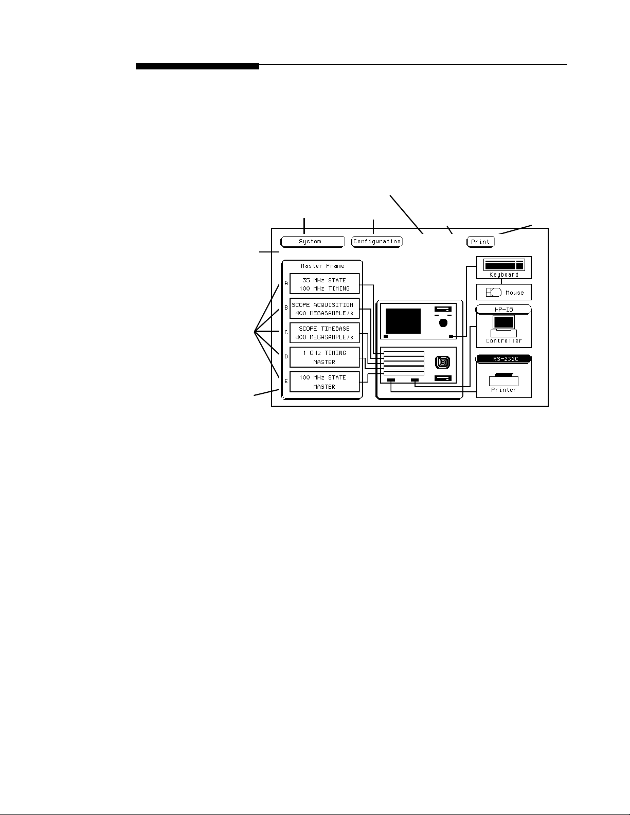
Layout of the
System
Configuration
Menu
RS-232C field
indicating that the
RS-232C interface is
setupforaprinter
Slot
Designators
The figures below show the layout of the System Configuration menu for
the HP 16500A alone (figure 4-1) and with the 16501A attached (figure
4-2). Each figure is labelled with the major features and functions of the
menu.
HP-IB feild indicating
that the HP-IB
interfaceis set up for
ModuleField
a controller
Menu Field
Indicates that a mouse
is connected. If a
mouse isn’t connected,
this box isn’t displayed.
Print field to start
a hardcopy output
List of System Cards
Figure 4-1. The System Configuration Menu for the HP 16500A.
The System Configuration Menu
4-2
Page 50
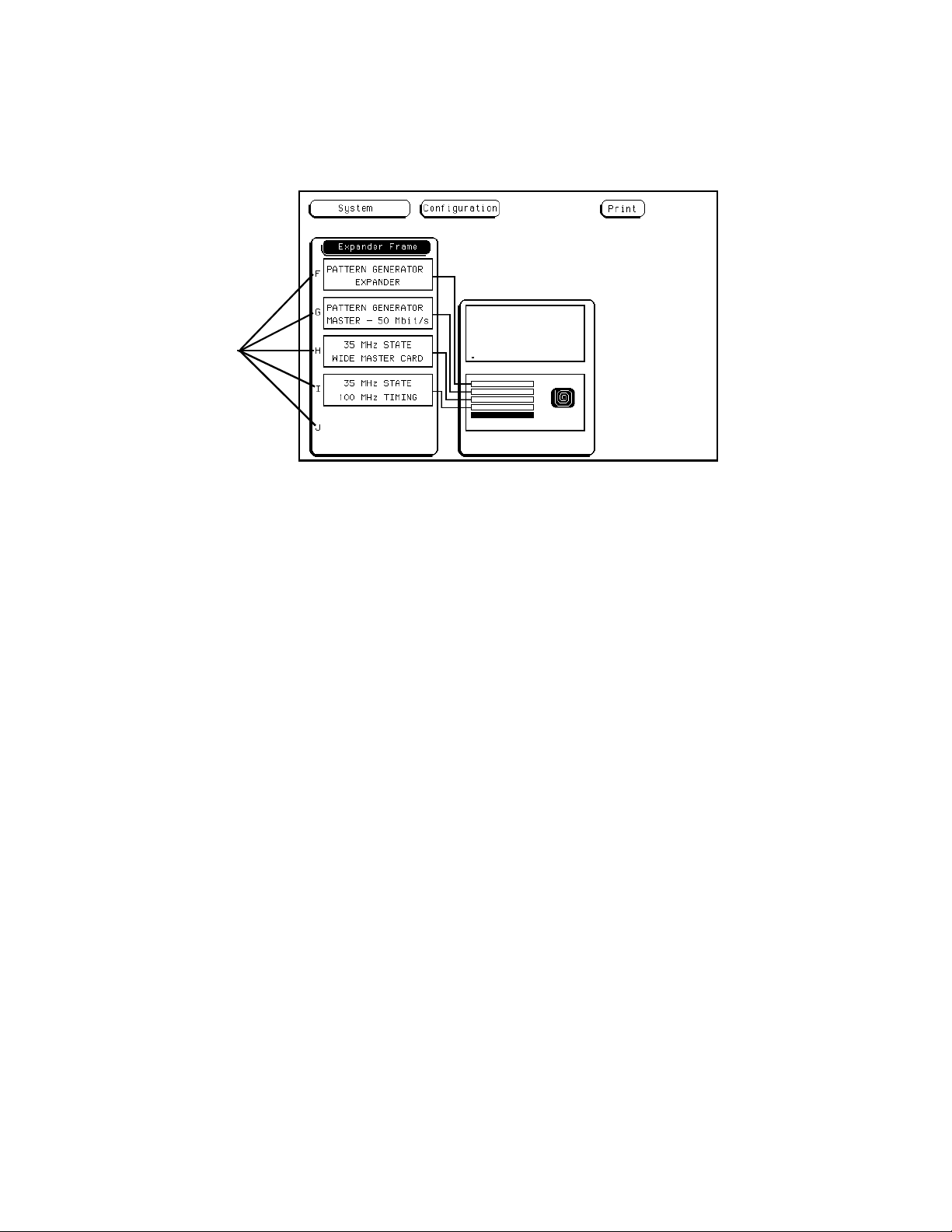
Slot
Designators
Figure 4-2. The System Configuration Menu for the HP 16501A.
The System Configuration Menu
4-3
Page 51
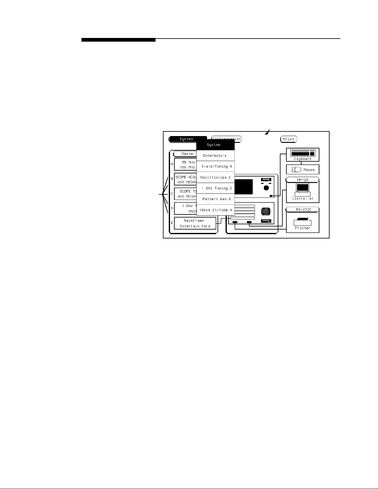
Slot
Designators
Location of Individual Cards
The slot designators are listed as A through E for the HP 16500A alone, or
A through J for the HP 16500A with the HP 16501A attached. The slot
designators are displayed to the left of the list of cards for the system and
indicate the locations or slots for each card. When you touch the module
field, a pop-up appears. The letters after the name of each module indicate
the location of each “master” card for that module. For example,
Oscilloscope D indicates that the master card for the Oscilloscope module
is in slot D of the instrument.
Location of “Master” Cards
Figure 4-3. Slot Designators for the HP 16500A/16501A.
The System Configuration Menu
4-4
Page 52
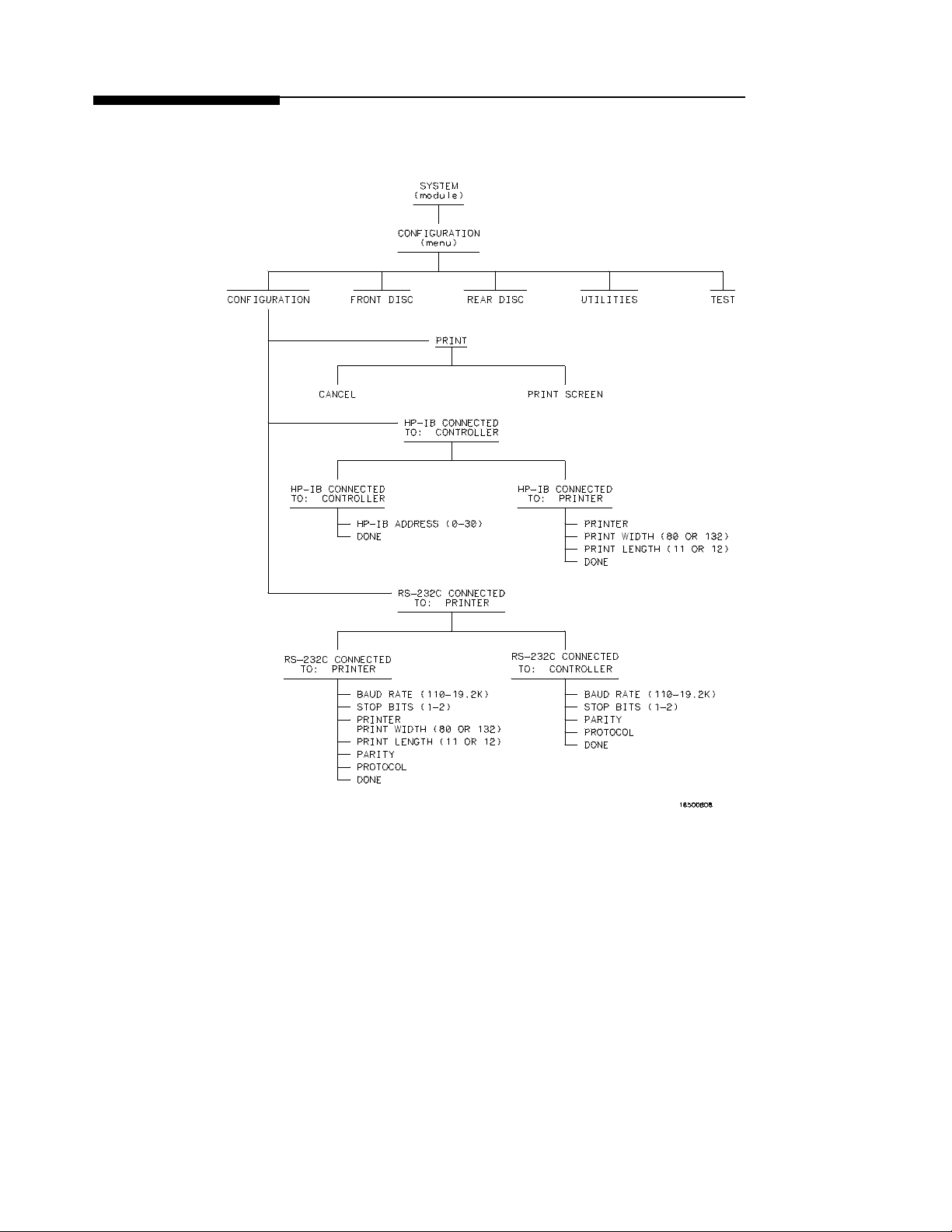
Menu Map Figure 4-5 displays a menu map for the System Configuration menu.
When the field has a numeric input, the range is displayed in parentheses.
Figure 4-4. Menu Map for the System Configuration Menu.
The System Configuration Menu
4-5
Page 53

HP-IB and RS-232C
This chapter describes the controller and printer interfaces and their
configuration. It defines the HP-IB interface and describes how to select
any one of the 31 different HP-IB addresses available. It also defines the
RS-232C interface and tells you how to select a baud rate, change the stop
bits, set the parity and data bits, and how to change the protocol.
5
The Controller
Interface
The Printer
Interface
What Is the
HP-IB
Interface?
The HP 16500A is equipped with a standard RS-232C interface and an
HP-IB interface that allow you to connect to a controller. This gives you
remote access for running measurements, for up-loading and
down-loading configurations and data, for outputting to a printer, and
more. The controller interface is explained in more detail in the HP
16500A/16501A System Programming Manual.
The HP 16500A can output its screen display to various HP-IB and
RS-232C graphics printers. Configured menus as well as waveforms and
other data can be printed for complete measurement documentation. The
printer interface is explained in more detail in Chapter 7.
The Hewlett-Packard Interface Bus (HP-IB) is Hewlett-Packard’s
implementation of IEEE Standard 488-1978, “Standard Digital Interface
for Programmable Instrumentation.” The HP-IB is a carefully defined
interface that simplifies the integration of various instruments and
computers into systems. It uses an addressing technique to ensure that
each device on the bus (interconnected by HP-IB cables) receives only the
data intended for it. To accomplish this, each device is set to a different
address and this address is used to communicate with other devices on the
bus.
HP-IB and RS-232C
5-1
Page 54

Selecting an
Address
The HP-IB address can be set to 31 different HP-IB addresses, from 0 to
30. Simply choose an address that is compatible with your device and/or
software. The default is 7.
To select an address:
1. Select the System Configuration menu and select the HP-IB field
on the right side of the menu by using touch or the optional mouse
or keyboard.
2. When the pop-up appears, use the knob, the pop-up keypad, the
mouse, or the keyboard to enter the address. To use the keypad,
touch the HP-IB Address fieldandapop-upkeypadwillappear.
Then enter the address and touch Done.
3. When you are finished configuring the HP-IB pop-up, touch Done.
What Is the
RS-232C
Interface?
The RS-232C interface on this instrument is Hewlett-Packard’s
implementation of EIA Recommended Standard RS-232C, “Interface
Between Data Terminal Equipment and Data Communications Equipment
Employing Serial Binary Data Interchange.” With this interface, data is
sent one bit at a time and characters are not synchronized with preceeding
or subsequent data characters. Each character is sent as a complete entity
without relationship to other events.
Baud Rate The baud rate is the rate at which bits are transferred between the interface
and the peripheral. The baud rate must be set to transmit and receive at
thesamerateastheperipheral,ordatacannotbesuccessfullytransferred.
To set the baud rate:
1. Select the System Utilities menu and touch the RS-232C field.
2. When the pop-up menu appears, touch the field directly to the right
of “Baud Rate.”
3. When the second pop-up appears, touch the baud rate you want
from the list displayed in the pop-up (110 to 19.2k) and the pop-up
will disappear.
HP-IB and RS-232C
5-2
Page 55
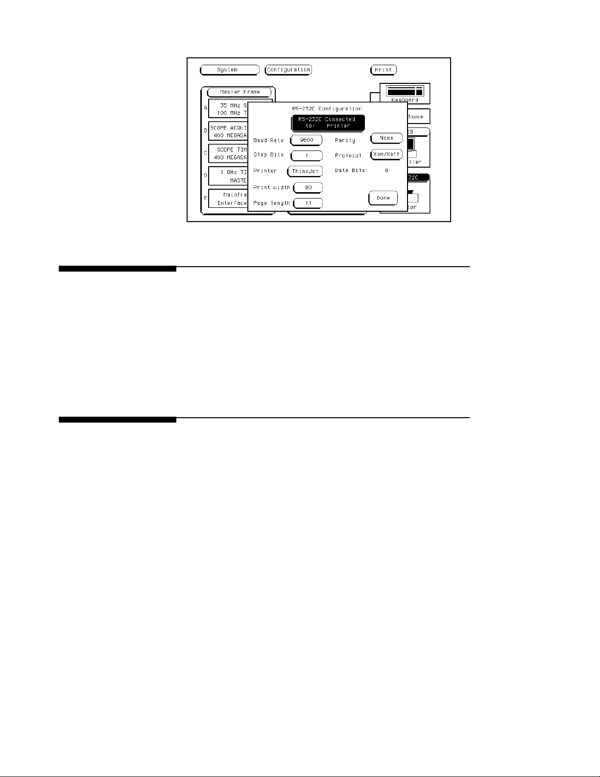
Figure 5-1. RS-232C Pop-up.
Stop Bits Stop Bits are used to identify the end of a character. The number of Stop
Bits must be the same for the controller as for the Logic Analysis System.
To change the Stop Bits:
1. Touch the field directly to the right of “Stop Bits” on the RS-232C
pop-up menu.
2. When the new pop-up appears, select either 1, 1.5,or2 Stop Bits to
identify the end of the character. The pop-up will disappear, placing
your selection in the appropriate field.
Parity The parity bit detects errors as incoming characters are received. If the
parity bit does not match the expected value, the character is assumed to
be incorrectly received. The action taken when an error is detected
depends on how the interface and the device program are configured.
Parity is determined by the requirements of the system. The parity bit
may be included or omitted from each character by enabling or disabling
the parity function. To set the parity bit:
HP-IB and RS-232C
5-3
Page 56

1. Touch the field directly to the right of “Parity” on the RS-232C
pop-up menu.
2. When the pop-up appears, select either None, Odd,orEven to
match the parity of the external device. After you make your
selection, the pop-up disappears.
Data Bits Data bits are the number of bits sent and received per character that
represent the binary code of that character. The HP 16500A supports the
8-bit binary code.
Protocol Protocol governs the flow of data between the instrument and the external
device. To change the protocol:
1. Touch the field directly to the right of “Protocol” on the RS-232C
pop-up.
2. When the pop-up appears, select:
• None
-With less than a 5-wire interface, selecting None does not allow the
sending or receiving device to control how fast the data is being
sent. No control over the data flow increases the possibility of
missing data or transferring incomplete data.
HP-IB and RS-232C
5-4
-With a full 5-wire interface, selecting None allows a hardware
handshake to occur. With a hardware handshake, hardware signals
control data flow. The HP 13242G cable allows the HP
16500A/16501A to support hardware handshake.
• Xon/Xoff
-Xon/Xoff stands for Transmit On/Transmit Off. With this mode,
the receiver controls the data flow and can request that the printer
stop data flow at any time.
After you make your selection, the pop-up disappears.
3. Touch Done when you are finished setting up the RS-232C
configuration pop-up.
Page 57
Configuring the
Interface for a
Controller or a
Printer
To configure the HP-IB or RS-232C interfaces for a controller or a printer,
firstselecttheSystem Configuration menu. Then touch the appropriate
field for the interface you want to configure (RS-232C or HP-IB). When
the pop-up appears, touch the field at the top of the pop-up to switch
between a printer and a controller configuration. Whenever you change
the configuration for one interface, the other interface automatically
changes to the opposite configuration.
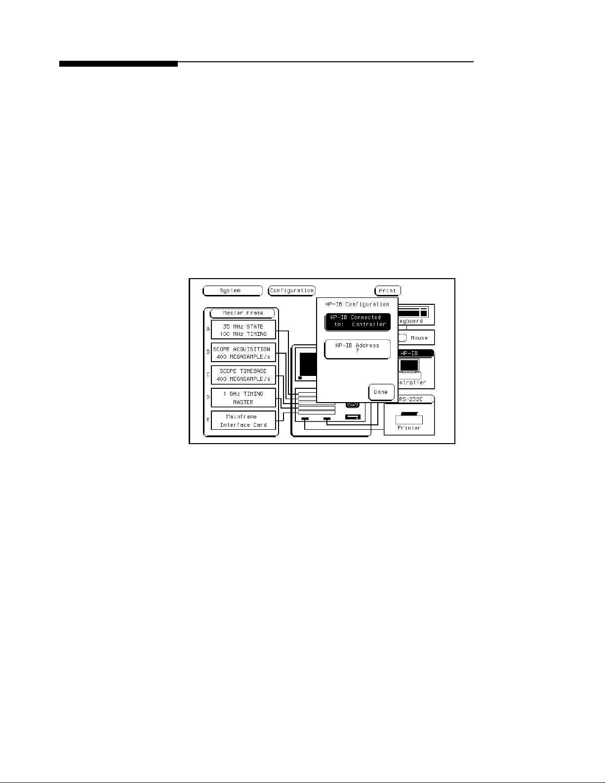
For example, to configure the HP-IB interface for a printer:
1. Select the System Configuration menu and touch the HP-IB field.
2. When the pop-up appears, touch the field displaying HP-IB
Connected to: Controllerand it changes to HP-IB Connected to:
Printer. At the same time, the RS-232C interface automatically
changes from a printer to a controller configuration.
Figure 5-2. HP-IB Printer Configuration.
The HP-IB printer must be set to Listen Always for the HP-IB interface.
In this mode, no HP-IB addressing is necessary, so the HP-IB address
field is not displayed. Three additional fields then appear to allow you to
select the printer type, character width, and page length.
HP-IB and RS-232C
5-5
Page 58

To return to the HP-IB controller interface:
1. Touch the field displaying HP-IB Connected to: Printer and it
changes back to HP-IB Connected to: Controller. Automatically,
the RS-232C interface switches back to a printer configuration.
2. Touch Done and the HP-IB pop-up disappears.
HP-IB and RS-232C
5-6
Page 59

The Optional HP 16501A Expansion
Frame
The HP 16501A Expansion Frame has been developed to extend the HP
16500A Logic Analysis System beyond its present five-card limit and
meet the anticipated need for systems requiring more than five slots.
This chapter explains the features, components, and system configuration
of the HP 16501A. There are sections explaining and illustrating
module-to-module system arming and triggering, as well as an interframe
arming/triggering block diagram. In addition, this chapter contains a
detailed explanation of how to connect the HP 16501A to the HP 16500A.
Features Adding the HP 16501A to the HP 16500A creates a tightly coupled two
frame, nine-card system fully controlled by the HP 16500A. A single
power switch (located on the HP 16500A front panel) turns on both
mainframes. The HP 16501A offers inter-frame module arming/triggering
capabilities with a 10 nanosecond time correlation between modules.
6
Component
Details
Expansion Frame
Interface Board
The HP 16501A Expansion Frame consists of the HP 16500A system
package, card cage, rear panel, power supply, and fans. Included as part of
the HP 16500A system package are two PC boards which enable you to
connect the HP 16501A to the HP 16500A.
The expansion frame cotnrol board, which occupies the bottom slot in the
HP 16501A card cage, uses a buffering scheme to pass signals between
the mainframe interface board and the HP 16501A back plane. It contains
circuitry which controls external arming selection and enables an HP
16501A card to drive an output dedicated to triggering other instruments.
The Optional HP 16501A Expansion Frame
6-1
Page 60
Main Frame
Interface Board
The main frame interface board, which occupies one of the five card slots
in the HP 16500A mainframe, has two functions:
• To pass signals between the HP 16500A rear panel and the
expansion frame interface board.
• To capture and correlate all trigger signals generated by both the HP
16500A and the HP 16501A.
System
Configuration
The expansion frame interface board is connected to the main frame
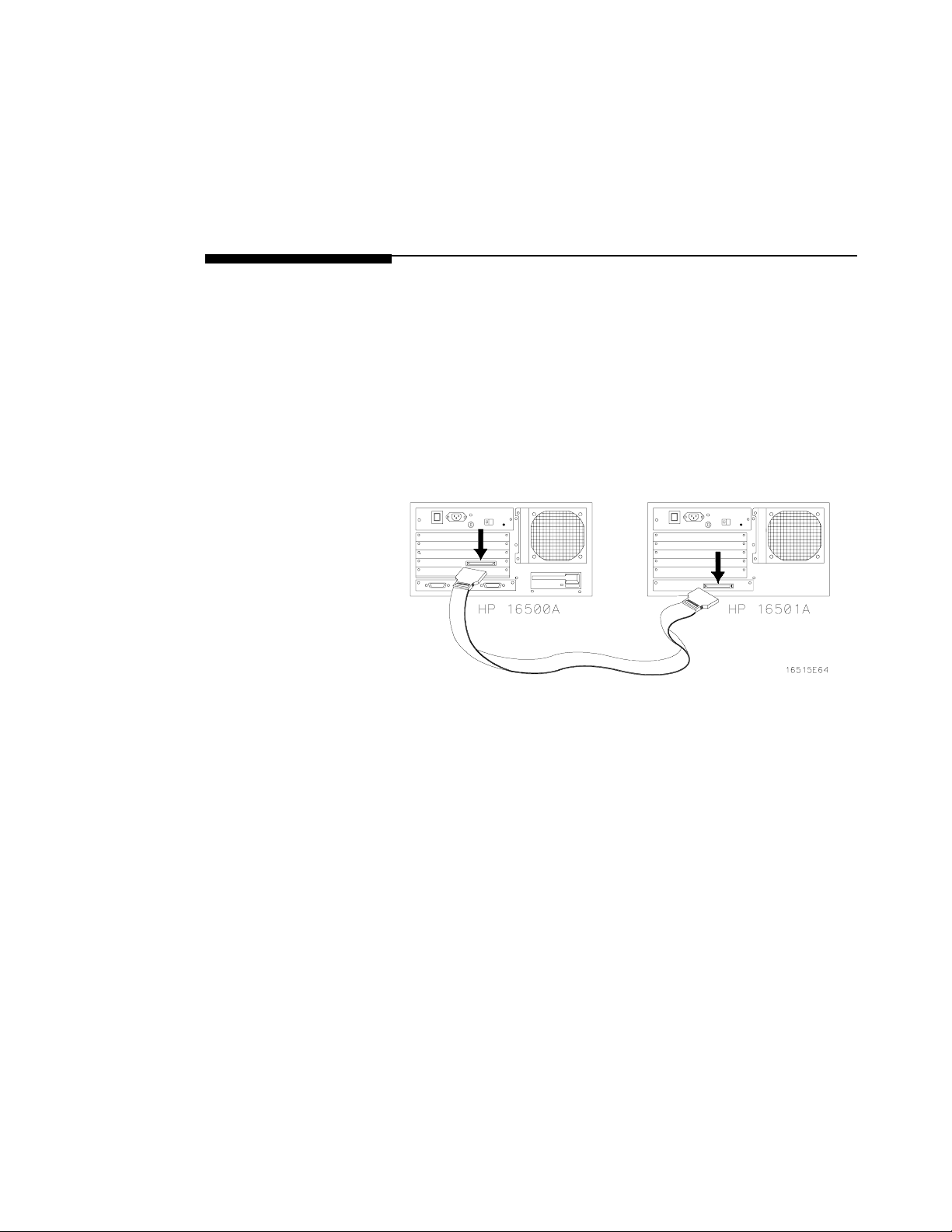
interface board through a 68-pin flat cable. In addition to the HP 16500A
rear panel signals, the cable incorporates control signals which allow the
CPU to communicate with and control the expansion frame interface
board. Ground lines separate signal lines within the cable to prevent
cross-coupling or soft failures. The cable is externally shielded to reduce
RFI emissions. Figure 6-1 shows one of the possible connection
configurations.
Figure 6-1. Possible Connection Configurations.
The Optional HP 16501A Expansion Frame
6-2
Page 61
System Arming
and Triggering
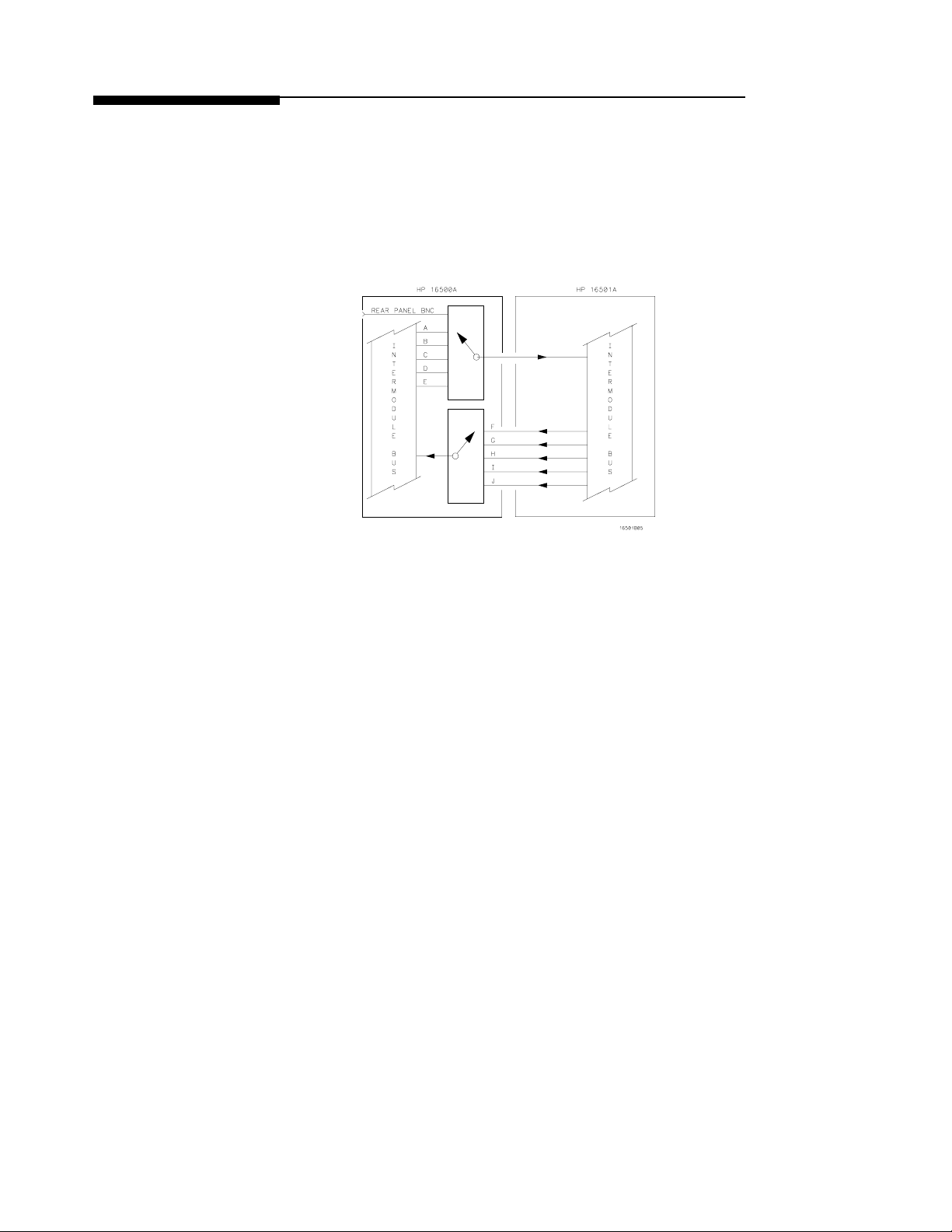
Module-to-module arming within the HP 16501A follows the arming
specifications for the HP 16500A in that any module may arm any other
module. The maximum intermodule arming level is five.
When the HP 16501A is attached to the HP 16500A, the resulting HP
16500A/16501A system operates as a single frame. TheHP 16500A and
HP 16501A may receive only one external arming signal from the other
frame. Figure 6-2 shows how module-to-module arming is selected.
Figure 6-2. Module-to-Module Arming.
The HP 16500A mainframe may use only two external arming signals:
any module in the HP 16501A expansion mainframeor the rear-panel
BNC. The arming signal can come from three sources:
• Any module in the HP 16500A mainframe.
• Any module in the HP 16501A expansion mainframe.
• From the rear-panel Port In BNC.
The arming signal from the HP 16501A is applied to the arm-out/trigger
line dedicated to the slot occupied by the Mainframe Interface board
(A-E). The external source has its own separate line.
Any card in the HP 16500A mainframe can be armed from its external
inputs or from one of the other three cards in the HP 16500A mainframe.
The Optional HP 16501A Expansion Frame
6-3
Page 62

Note
The HP 16501A expansion mainframe may use only one external arming
signal. The arming signal for any module can come from two sources:
• Any module in the HP 16501A expansion mainframe.
• From a single module or the Port In BNC in the HP 16500A
mainframe.
Any module in the HP 16501A expansion mainframe may be armed from
a single HP 16500A module or from one of the other four modules in the
HP16501A expansion mainframe.
To summarize, the arming triggers available for output from the HP
16500A/16501A are:
• HP 16500A
- Module A through Module E.
-PortInBNC.
• HP 16501A
- Module F through Module J.
Only the HP 16500A has a Port Out BNC. There is no Port Out BNC on
the HP 16501A. The Port Out signals from module F through module J
use the Port Out BNC on the HP 16500A.
For detailed information about how to make intermodule measurements
using the HP 16500A/16501A, please see Chapter 12.
The Optional HP 16501A Expansion Frame
6-4
Page 63

Connecting the
HP 16501A
Expansion
Frame
Note
The optional HP 16501A Expansion Frame has four components:
• The expansion frame.
• An expansion frame interface board.
• A main frame interface board.
• A flat, bi-directional cable 2 meters long with a 68-pin “D”
connector at each end.
To connect the HP 16501A to the HP 16500A, follow these steps:
1. Check to see if the main frame interface board is already installed in
the HP 16500A mainframe. If it is not already installed, insert it
into any one of the five card slots marked A-E (see “Installing and
Removing Cards” in Appendix F).
2. Insert one of the cable connectors into the port located on the
right side of the mainframe interface board.
3. Insert the other connector into the port on the expansion
frame interface board.
In order to ensure correct insertion, the 68-pin “D” connectors are
asymmetric in shape. They only fit into their respective ports when
oriented to match the shape of the ports.
The Optional HP 16501A Expansion Frame
6-5
Page 64
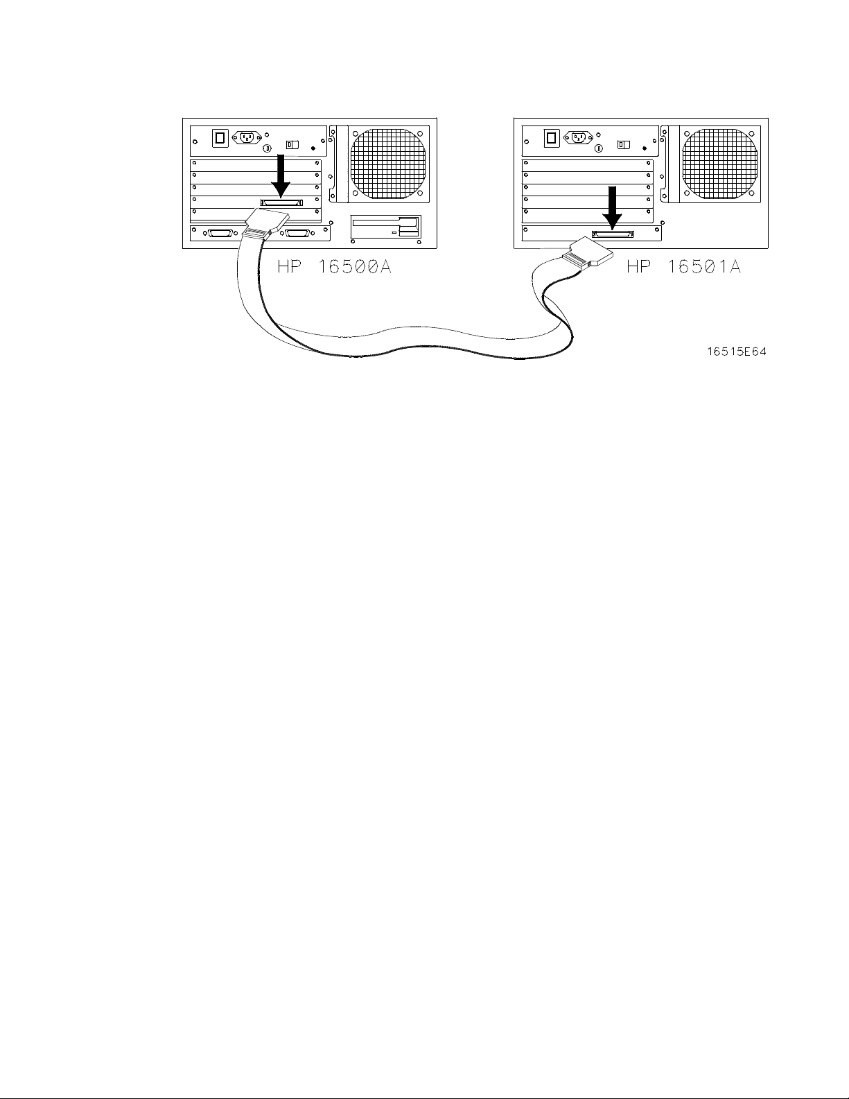
Figure 6-3 Connecting the optional HP 16501A Expansion Frame.
If, at power-up, the HP 16500A CPU board finds a mainframe interface
board in any one of its five card slots, it checks the expansion frame
interface board to determine whether an HP 16501A expansion mainframe
is present. If so, the CPU establishes a “link” between the rear panels of
the two mainframes, which then are displayed by the System
Configuration menu as a nine-slot system on the HP 16500A rear panel.
The Optional HP 16501A Expansion Frame
6-6
Page 65
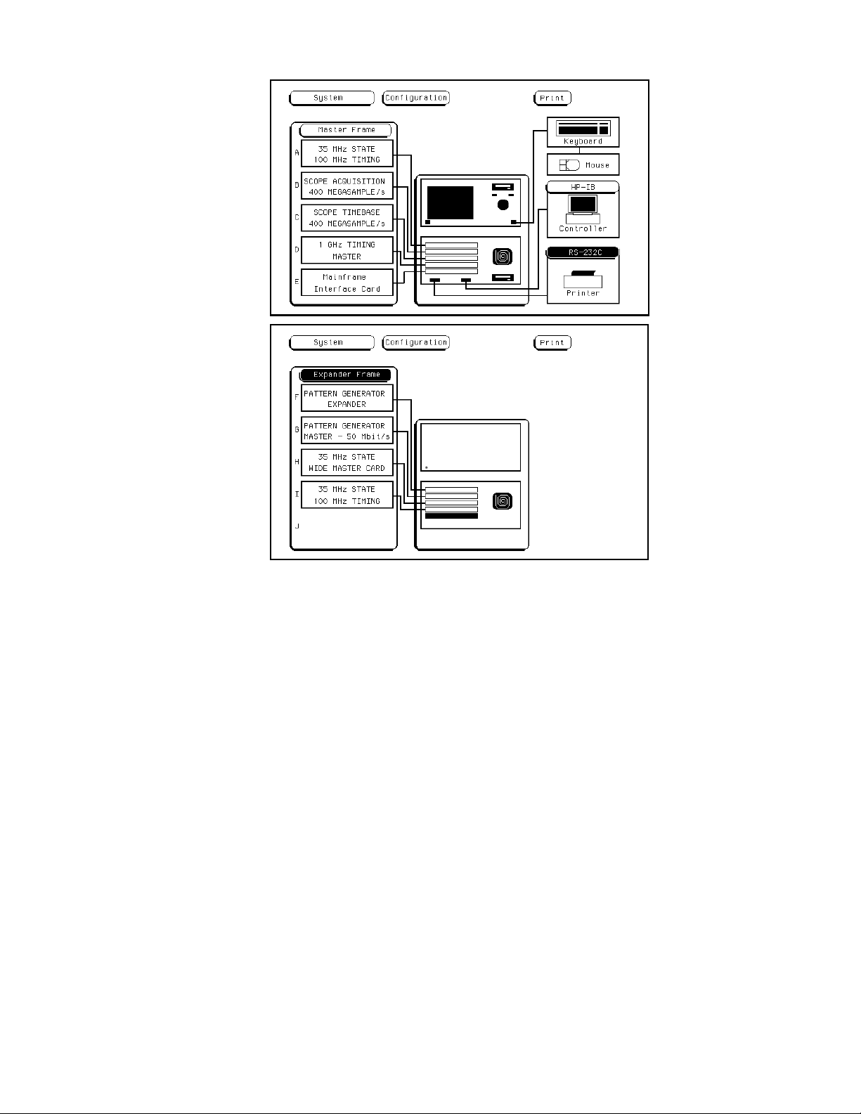
Figure 6-4. System Configuration menus with the HP
16501A connected.
The Optional HP 16501A Expansion Frame
6-7
Page 66

Connecting a Printer
The HP 16500A can output its screen display to various HP-IB and
RS-232C graphics printers. Configured menus as well as waveforms and
other data can be printed for complete measurement documentation.
HP-IB Printers The HP 16500A interfaces directly with HP PCL printers supporting the
printer command language or with Epson printers supporting the Epson
standard command set. These printers must also support HP-IB and
Listen Always Printers currently available from Hewlett-Packard with
these features include:
• HP ThinkJet.
• HP LaserJet.
• HP PaintJet.
• HP DeskJet.
The printer must be in Listen Always when HP-IB is the printer interface.
Note
7
Note
HP-IB Printer
Setup
The HP 16500A HP-IB port does not respond to service requests (SRQ)
when controlling a printer. The SRQ enable setting for the HP-IB printer
has no effect on HP 16500A printer operation.
To set up the printer for the HP 16500A:
1. Turn off the HP 16500A and connect an HP-IB cable from the
printer to the HP-IB connector on the rear panel of the HP 16500A.
Connecting a Printer
7-1
Page 67
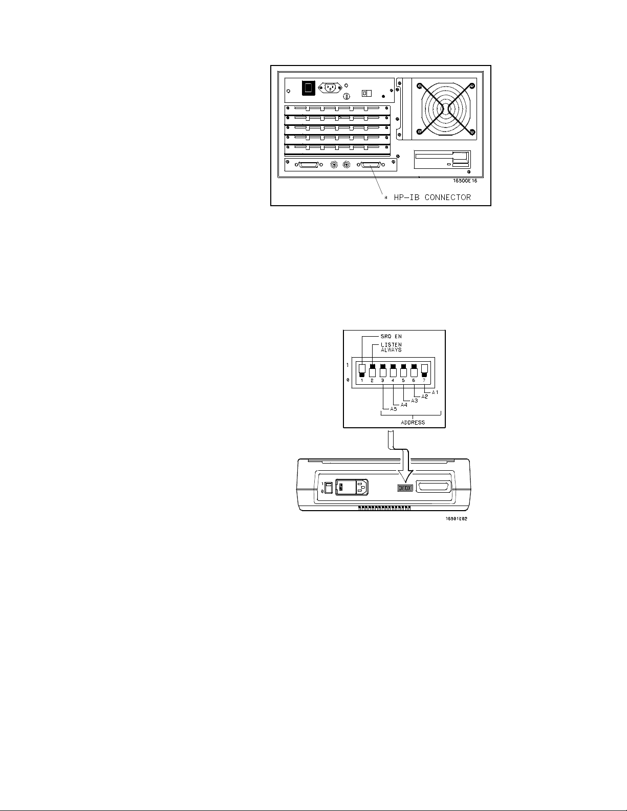
Figure 7-1. HP 16500A/16501A Rear Panel.
2. Make sure the printer is in Listen Always (or Listen Only). For
example, figure 7-2 shows the HP-IB configuration switches for an
HP-IB ThinkJet printer. For the Listen Always mode, move the
second switch from the left to the “1" position. Since the HP
16500A doesn’t respond to SRQ EN (Service Request Enable), the
position of the first switch doesn’t matter.
Connecting a Printer
7-2
Figure 7-2. Configuration Switches for the HP
ThinkJet Printer.
Page 68

HP-IB
Configuration
Turn on the HP 16500A and when the System Configuration menu is
displayed:
1. Touch the HP-IB field.
2. When the pop-up appears, touch HP-IB Connected to: Controller
to switch from a controller to a printer configuration. This
automatically switches the RS-232C interface from a printer to a
controller configuration.
3. Touchthefieldtotherightof“Printer”andwhenthepop-up
appears, select the printer that you’re using (ThinkJet, QuietJet,
etc.). If you’re using an Epson graphics printer or an
Epson-compatible printer, select Alternate.
Figure 7-3. HP-IB Printer Interface Pop-up.
4. Touch the Print Width field and print width toggles between 80
and 132. Select the width for your application or leave it at the
default of 80. Print width tells the printer that you are sending up to
80 or 132 characters per line (when you Print All) and is totally
independent of the printer itself.
Connecting a Printer
7-3
Page 69

• If you select 132 charactersper line when using other than the
QuietJet selection, the listings are printed in a compressed mode.
Compressed mode uses smaller characters to allow the printer to
print more characters within a given area.
• If you select 132 characters per line for the QuietJet selection it can
print a full 132 characters per line without going to compressed
mode, but the printer must have wider paper.
• If you select 80 characters per line for any printer, a maximum of 80
characters are printed per line.
5. Touch the Print Length field and print length toggles between 11
and 12. Select the length for your application or leave it at the
default of 11. Print length tells the printer the page length for the
type of paper you are using.
6. Touch Done when you finish setting up the HP-IB pop-up.
RS-232C
Printers
RS-232C
Printer Setup
Connecting a Printer
7-4
The HP 16500A interfaces directly with RS-232C printers including the
HP ThinkJet, HP QuietJet, HP LaserJet, HP PaintJet, and HP DeskJet
printers.
To set up the printer for the HP 16500A:
1. Turn off the HP 16500A and connect an RS-232C cable (HP
13242G) from the printer to the RS-232C connectoron the rear
panel of the HP 16500A.
Page 70
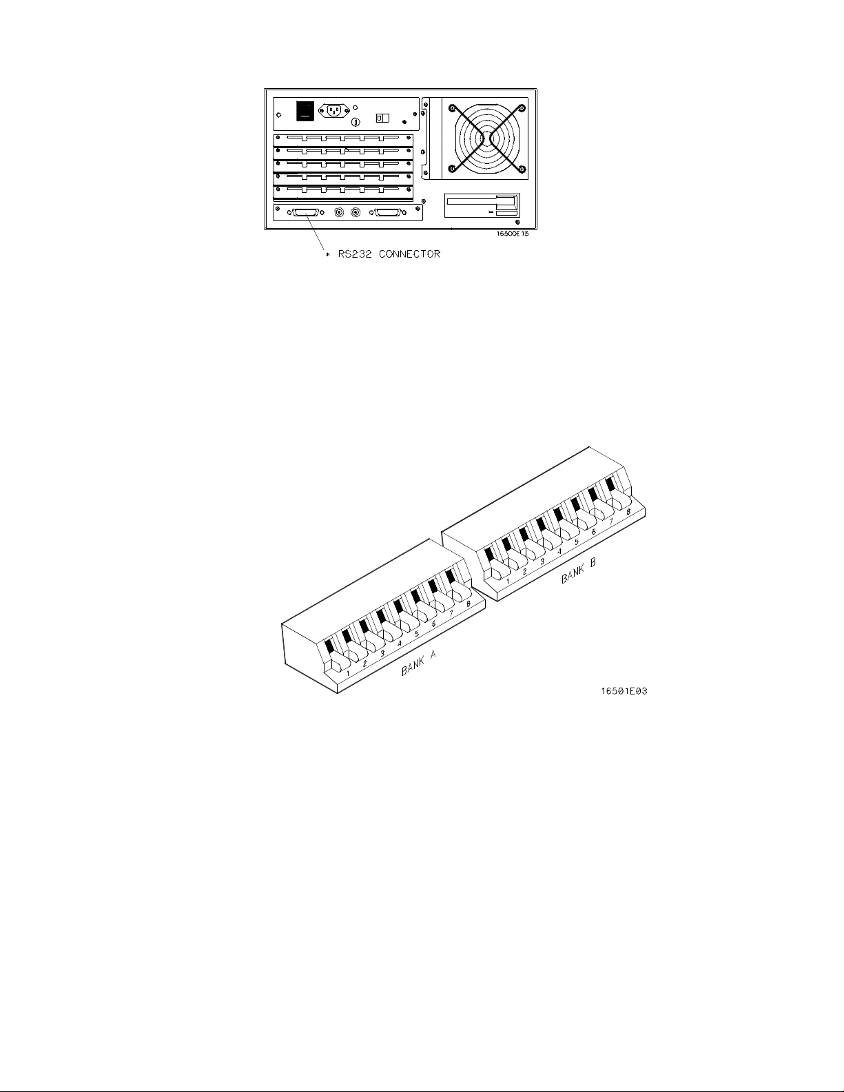
Figure 7-5. HP 16500A Rear Panel.
2. Before turning on the printer, locate the mode configuration
switches on the printer. Then configure the printer as follows:
• The HP QuietJet series printers have two banks of mode function
switches inside the front cover. Push all the switches down to the
“0" position as shown in figure 7-5.
Figure 7-4. Switch Configuration for HP QuietJet Printers.
Connecting a Printer
7-5
Page 71
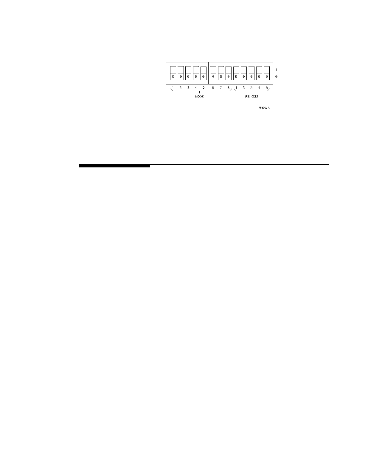
• For the HP 2225D (RS-232 HP ThinkJet) printer, the mode switches
are on the rear panel of the printer. Push all the switches down to
the “0" position as in figure 7-6.
Figure 7-6. Switch Configuration for HP
ThinkJet Printers.
• For the HP LaserJet printer, the switch settings can remain in the
factory default settings.
RS-232C
Configuration
Connecting a Printer
7-6
Turn on the HP 16500A and when the System Configuration menu is
displayed:
1. Touch the RS-232C field.
2. When the pop-up appears, the top field should display RS-232C
Connected to: Printer. If not, touch this field to switch to a printer
configuration. This automatically switches the HP-IB interface
from a printer to a controller configuration.
3. Set the baud rate, stop bits, parity, and protocol to match the setup
for the RS-232C printer by selecting the appropriate fields.
Page 72
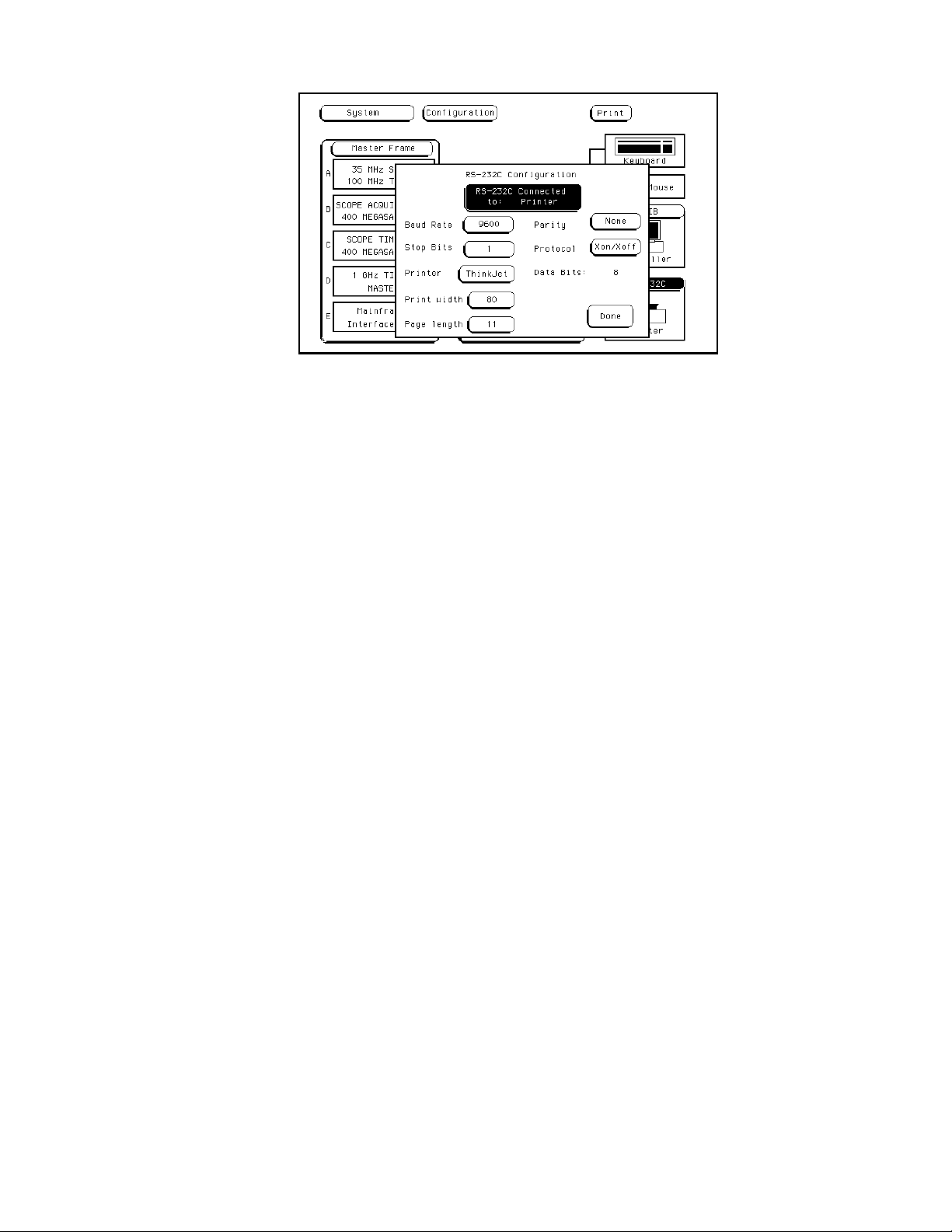
Figure 7-7. RS-232C Printer Interface Pop-up.
4. Set the Printer field to match the type of printer you are using
(ThinkJet, QuietJet, etc.).
5. Touch the field to the right of Print Width and print width toggles
between 80 and 132. Select the width for your application or leave
it at the default of 80. Print width tells the printer that you are
sending either 80 or 132 characters per line (when you Print All)
and is totally independent of the printer itself.
6. Touch the Print Length field and print length toggles between 11
and 12. Select the length for your application or leave it at the
default of 11. Print length tells the printer the page length for the
type of paper you are using.
7. Touch Done when you finish setting up the RS-232C pop-up.
Connecting a Printer
7-7
Page 73

Configuration
Example
Figure 7-8 shows how the RS-232C configuration pop-up is configured
for the HP LaserJet printer. The only difference between this
configuration and the configuration for the HP QuietJet and HP ThinkJet
printers is the printer selection. All the other fields remain in their default
settings.
Figure 7-8. RS-232C Configuration for HP LaserJet
Printers.
Connecting to
Other
Hewlett-Packard
Printers
Connecting a Printer
7-8
The HP 16500A can also be used with other Hewlett-Packard graphics
printers. Simply connect the printer to the HP 16500A using the
appropriatecable (HP-IB or RS-232C) and configure the HP 16500A as
shownintable7-1.
Page 74
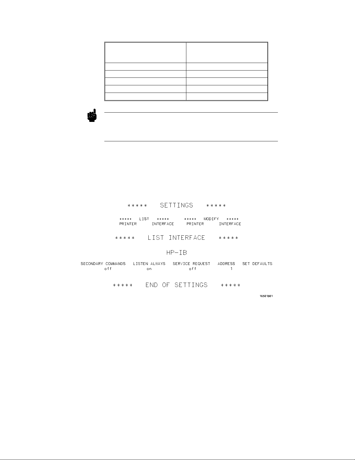
Table 7-1. HP Printer Selection
Select this Printer
For this HP Printer
HP 2631G QuietJet
HP 2671G ThinkJet
HP 2673A ThinkJet
HP 9876A ThinkJet
HP 2932/34 (option 046) QuietJet
from the pop-up
Note HP-IB printers must support Listen Always to work with the HP 16500A.
The HP 82906A graphics printer is not supported because it does not
support Listen Always on HP-IB.
The HP 2932A or HP 2934A option 046 printer is configured from the
front panel of the printer, instead of with switches on the rear panel. The
correct configuration for the HP 16500A is shown in figure 7-9.
Refer to the HP 16500A/16501A Programming Manual for information on
setting up an external controller to activate the printer.
Figure 7-9. Configuration for the HP 2932/34 Option 046.
Connecting a Printer
7-9
Page 75

Printing the
Display
Note
After connecting the printer to the instrument and setting the printer and
instrument configurations, apply power to the printer.
Each menu has a Print field in the upper-right corner. Touch the Print
fieldandapop-upappears,displayingyourchoices.
• Cancel is used to stop the HP 16500A from sending data.
• Print Screen prints everything shown on the screen.
• Print All (available only in certain menus) prints all of the
information listed for that display, including any listings that do not
appear on screen. These listings can be 80 or 132 characters wide,
depending on the Print Width setting.
To initiate a print, touch Print Screen or Print All, at which point the
Cancel field will replace the print field.
The HP 16500A does not check the operation of the printer, so no error
message is displayed.
Connecting a Printer
7-10
Page 76
The System Front and Rear Disk Menus
This chapter describes the disk operations of the HP 16500A/16501A and
tells you how to get into the system’s Front and Rear Disk menus. It
explains the menu map and describes how to select a disk operation and
designate source and destination disks. It tells you how to install, format,
store, and duplicate a disk, as well as how to purge, copy, and rename a
file. Thischapter also describes the Load, Autoload, and Pack Disk
operations.
The HP 16500A disk drives support only double-sided, double-density
Note
disks.
8
Getting into the
System Front
Disk Menu
Note
TobringuptheSystem Front Disk menu:
1. Touch the menu field to the right of System in the upper-left corner
of the display.
2. When the pop-up appears, touch Front Disk to bring up the System
Front Disk menu.
The System Front and Rear Disk menus operate in the same manner.
The System Front and Rear Disk Menus
8-1
Page 77
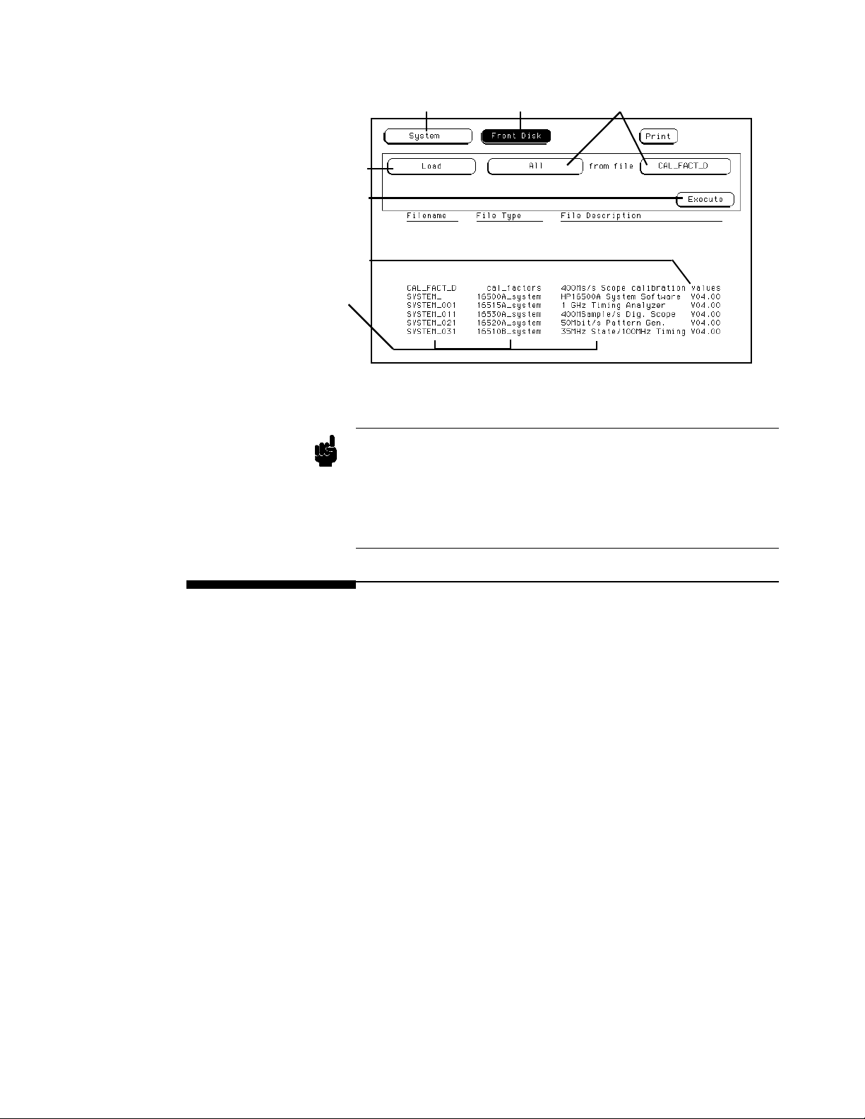
Disk
Operation
Execute Field
Software Version
List of Filenames,
Types, and Descriptions
Note
Module Field
Module Field
Disk Operation
Parameters
Figure 8-1. The System Front Disk Menu.
The software version numbers (VXX.YY) shown in this manual may be
different for your instrument. Also, the last two digits of the software
version number (YY) for specific modules may be different from other
modules without affecting software operation or compatibility. The first
two digits (XX) must be the same for all modules and system files within
aspecificmainframe.
The Disk
Operations
Nine disk operations are available:
Autoload Designates a set of configuration files to be loaded
Copy Any file can be copied from one disk to another or to
The System Front and Rear Disk Menus
8-2
automatically the next time the HP 16500A/16501A
is turned on.
thesamedisk.
Page 78

Duplicate Disk All files from one disk are copied to another disk.
All files on the destination disk will be destroyed
with this operation. The copied files are packed on
the new disk as they are copied and the new disk is
formatted if it is required.
Format Disk Any double-sided, double-density 3.5 inch flexible
disk can be formatted or initialized. The directory
and all files on the disk will be destroyed with this
operation.
Load Instrument setup and data can be loaded from the
disk for the mainframe and modules.
Inverse assemblersfor analyzer modules can be
loaded.
Pack Disk This function packs files on a disk. Packing removes
all empty or unused sectors between files on a disk so
that more space is available for files at the end of the
disk.
Purge Any file on a disk can be purged (deleted) from the
disk.
Note
Rename Anyfilenameonadiskcanbechangedtoanother
name.
Store Instrumentsetupanddatacanbestoredondisk.
System files for mainframe and modules cannot be stored.
Although default values are provided for these disk operations, a disk
operation may require additional information from the user. This
information is entered by touching or selecting the appropriate fields
displayed for each disk operation. Disk operations are initiated by
touching the Execute field. If there is a problem or additional information
is needed to execute an operation, a pop-up appears near the center of the
screen displaying the status of the operation (displays an error message,
prompts the user to swap disks, etc.).
The System Front and Rear Disk Menus
8-3
Page 79
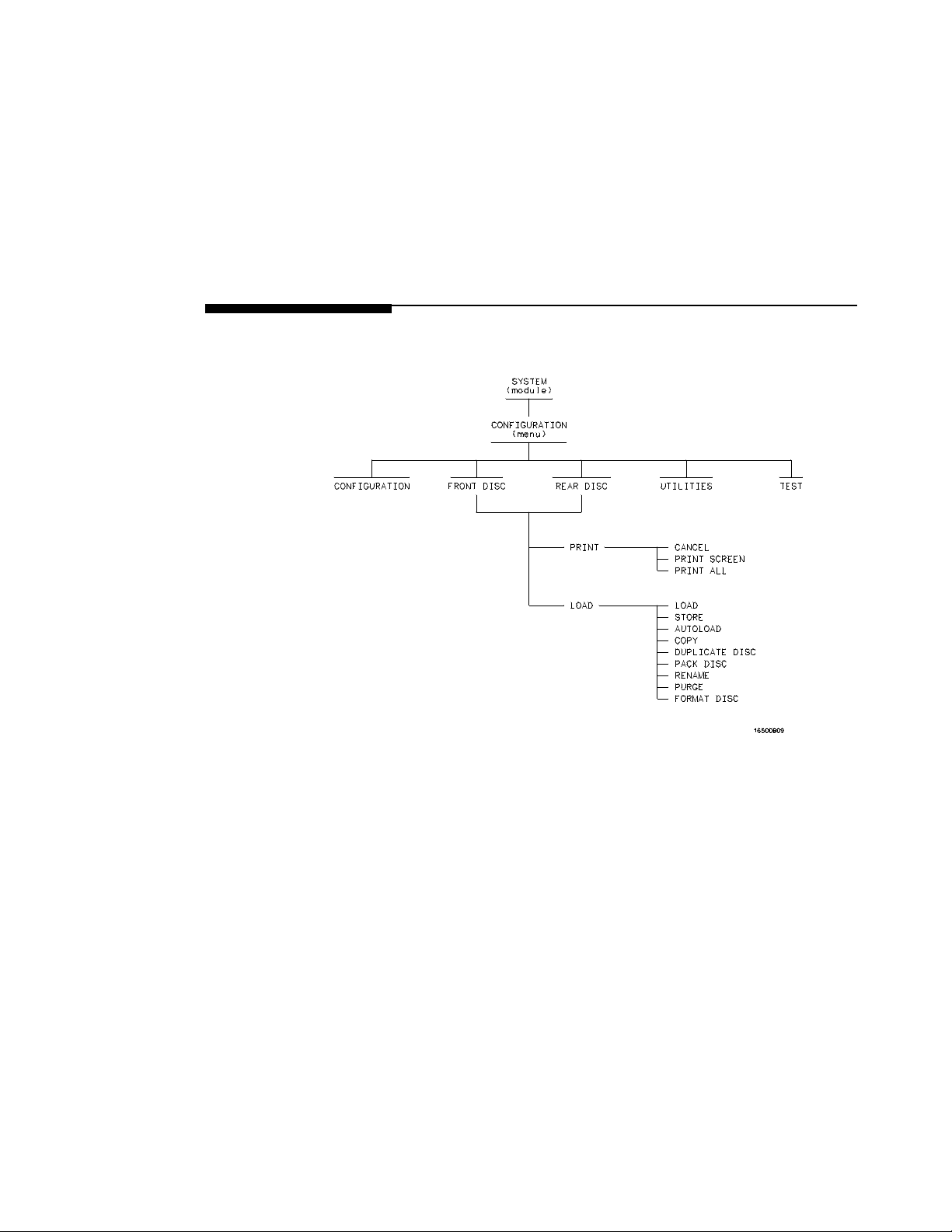
If executing a disk operation could destroy or damage a file, a pop-up
appears when you touch Execute. If you don’t want to complete the
operation, touch Cancel to cancel the operation. Otherwise, touch
Continue and the operation will be continued.
When a disk operation is being executed, the background of the Execute
field changes color. When the Execute field returns to the original color,
the disk operation is complete.
Whenever a disk drive is being accessed, an asterisk (*) appears in the
upper-right corner of the display.
Menu Map Figure 8-2 displays a menu map for the System Front and Rear Disk
menus.
Figure 8-2. Menu Map for the System Front and Rear Disk Menus.
The System Front and Rear Disk Menus
8-4
Page 80
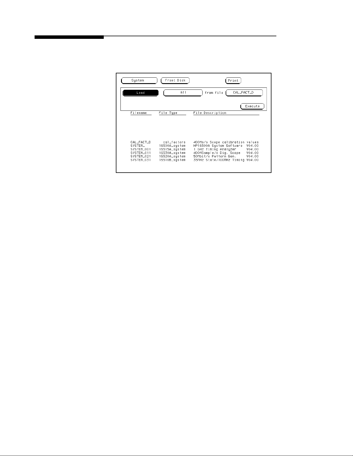
Selecting a
Disk Operation
To select a disk operation:
1. Touch the disk operation field directly below System on the display
(Load).
Figure 8-3. Selecting the Disk Operations Field.
2. When the pop-up appears, touch the field for the operation you
want. After you select a field, the pop-up disappears, bringing up
the appropriate operation. For example, touch Store.
The System Front and Rear Disk Menus
8-5
Page 81
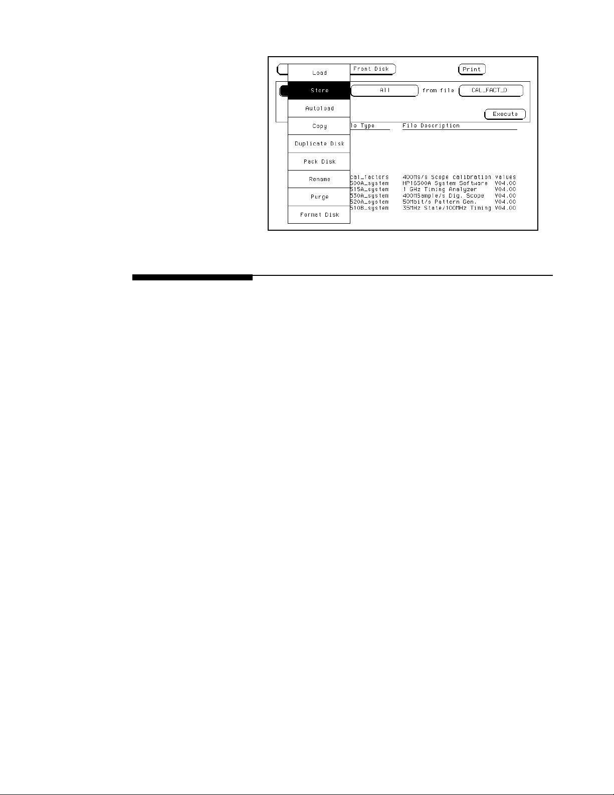
Figure 8-4. Selecting the Store Operation.
Disk Operation
Parameters
The System Front and Rear Disk Menus
8-6
The disk operation parameters specify which modules are being operated
on and give the names, types, and descriptions of files involved in the disk
operation.
After setting up the disk operation, touch Execute. When the background
of the Execute field returns to the original color, the disk operation is
complete.
Page 82
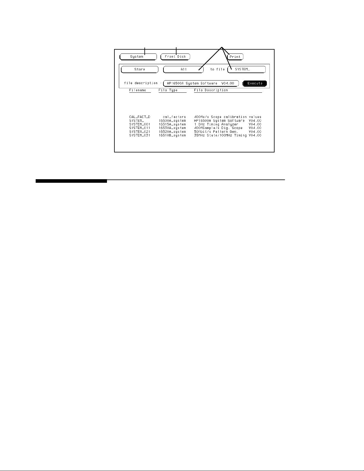
ModuleField
Figure 8-5. Disk Operation Parameters.
Menu Field
Disk Operation Parameters
Source and
Destination
Disks
The menu field (Front Disk or Rear Disk) indicates the location of the
disk on which you’re performing the operation. This disk is referred to as
the Source disk.
For the Copy operation and the Duplicate Disk operation, a disk
operation parameter is used to select the location of the disk to which the
information will be transferred (Front Disk or Rear Disk). This disk is
referred to as the Destination disk.
When you copy a disk (or duplicate a disk), you copy from the Source
disk (indicated by the menu field) to the Destination disk (indicated by
the disk operation parameter). You can use the same disk drive for both
the Source and Destination disks by just switching disks when necessary.
For the copy operation, the Source and Destination disks can be the same.
The System Front and Rear Disk Menus
8-7
Page 83
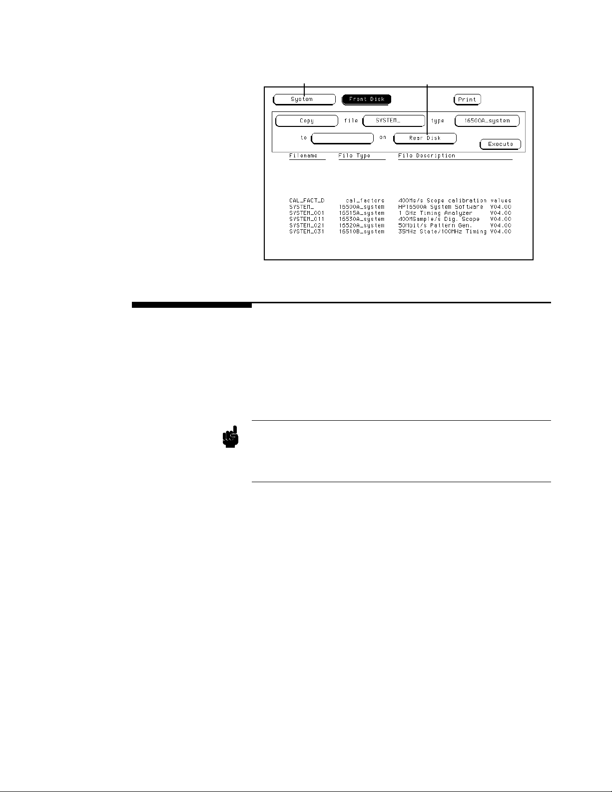
Location of Source Disk
(menu field)
Location of Destination Disk
(disk operation parameter)
Figure 8-6. Disk Locations.
Installing a Disk Included with the HP 16500A/16501A are two 3.5-inch flexible disks for
your own use. Either disk can be installed into the front or rear disk
drives. To install a disk:
1. Hold the disk so that the Hewlett-Packard label is on top and the
metal auto-shutter is away from you.
2. Push the disk gently, but firmly, into the front disk drive until it
clisks into place.
The HP 16500A disk drives use the gray Hewlett-Packard double-sided,
Note
double-density disks, which can be ordered in a package of ten with the
Hewlett-Packard part number 92192A. DO NOT use single-sided or high
density disks with the HP 16500A/16501A.
The System Front and Rear Disk Menus
8-8
Page 84
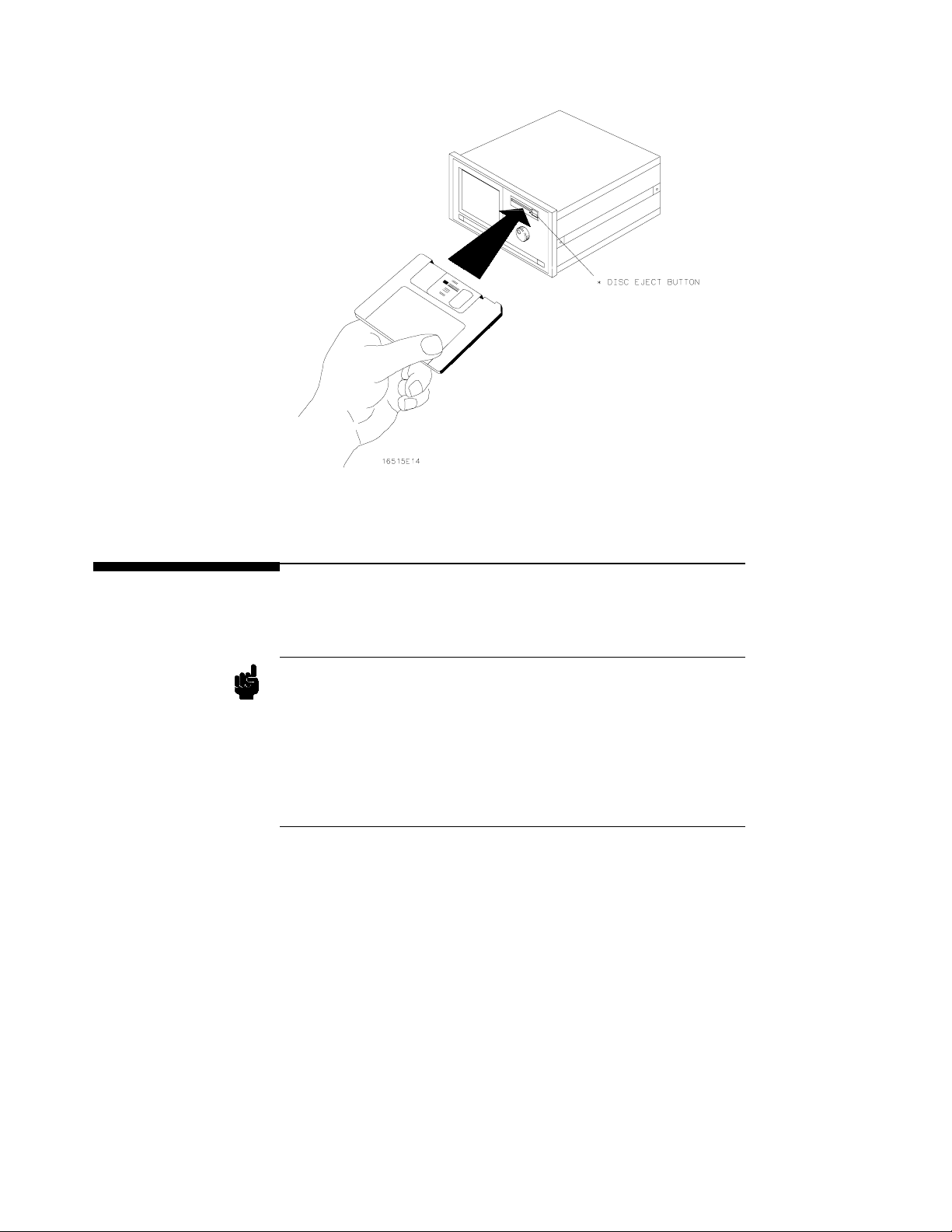
Figure 8-7. Installing a Disk.
Formatting a
Disk
Note
Before any information can be stored on a new disk, you must first format
it. Formatting marks off the sectors of the disk and creates the LIF
(Logical Interchange Format) directory on the disk.
The HP 16500A supports up to 144 entrys. If the disk was formatted
elsewhere with more than 144, the disk will be permanently changed if
you use it in the HP 16500A.
The HP 16500A does not support track sparing. If a bad track is found,
the disk is considered bad. If a disk has been formatted elsewhere with
track sparing, it is NOT compatible with the HP 16500A and will cause
unpredictable results.
The System Front and Rear Disk Menus
8-9
Page 85
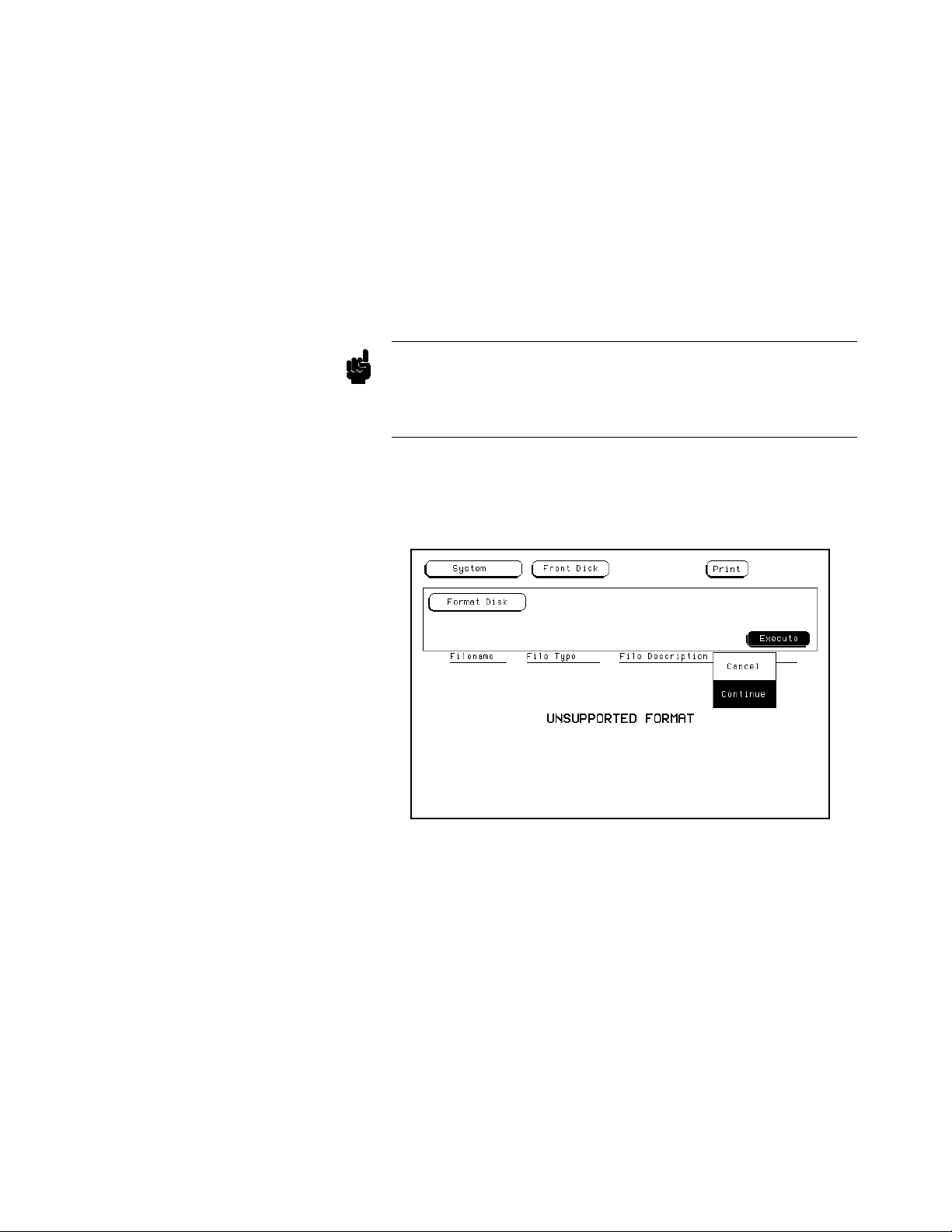
Note
To format a disk:
1. Select the Format Disk operation. After the Format Disk
operation appears, the instrument reads the disk and lists the files on
it.
• If this is a new disk, the menu will display “Unsupported Format”
on the lower portion of the menu.
• If it is already formatted, but there are no files on it, the menu will
display “No Files.”
• If the disk already has files, a list of those files will appear on the
lower portion of the menu along with a file type and description.
The HP 16500A supports (for both read and write) 256-byte and 512-byte
LIF formatted disks, but the HP 16500A will only format to 1024-byte
The HP 16500A does NOT support any single-sided formats.
2. To format the disk, touch Execute. When the pop-up appears, touch
Continue and the instrument will go through a sequence to format
the disk. Otherwise, touch Cancel to cancel the Format Disk
operation.
Figure 8-8. The Format Disk Operation.
The System Front and Rear Disk Menus
8-10
Page 86
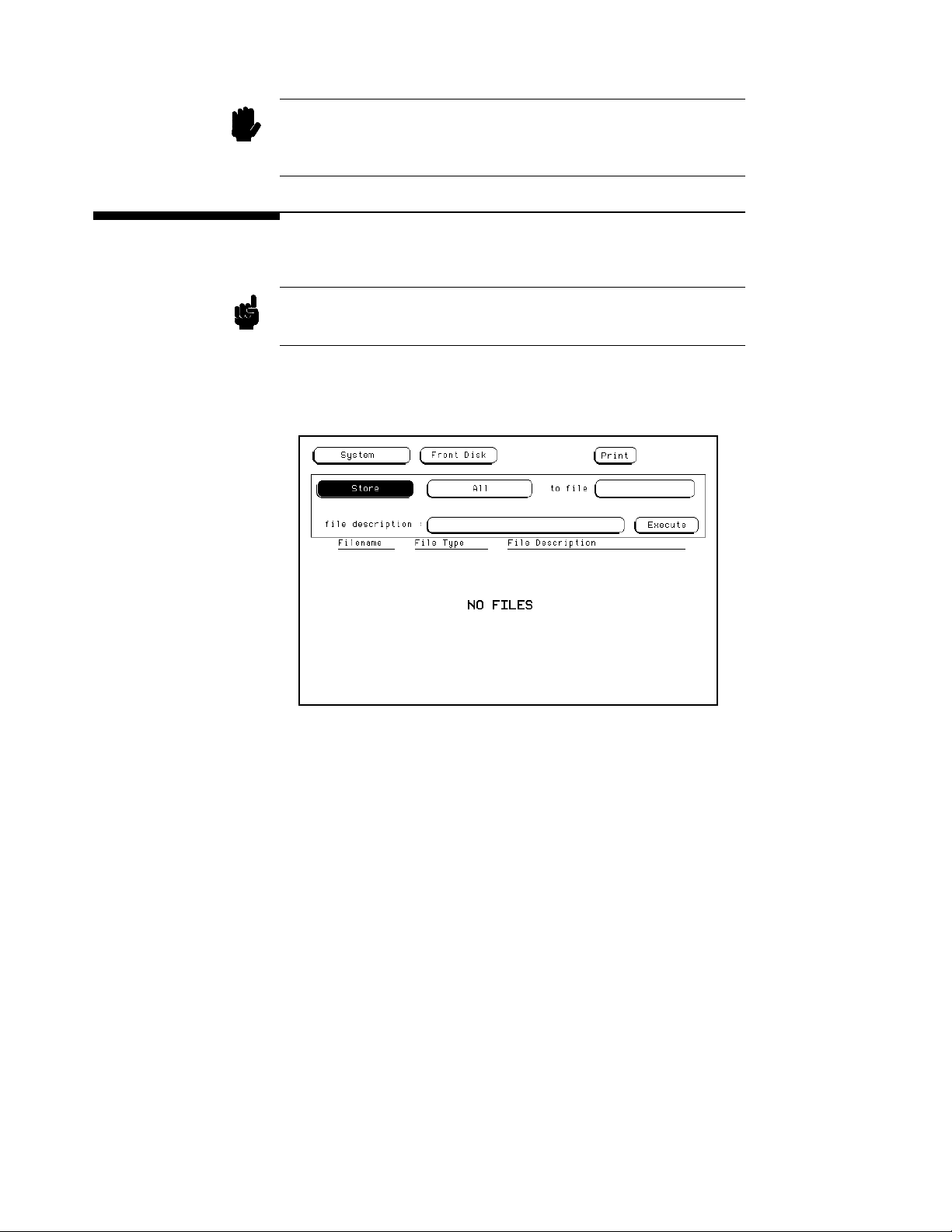
Caution
Once Executed,theFormat Disk operation permanently erases all the
existing information from the disk. After that, there is no way to retrieve
the original information.
Storing on a
Disk
Note
The Store operation allows you to store the configurations and data from
all of the modules or a particular module to a file with a given description.
Storing the default configurations is a convenient way to return to the
default values without cycling the power.
To store files:
1. Select the Store operation.
Figure 8-9. The Store Operation.
2. Touch the field to the right of “to file” and a pop-up appears
displaying an alphanumeric keypad.
The System Front and Rear Disk Menus
8-11
Page 87
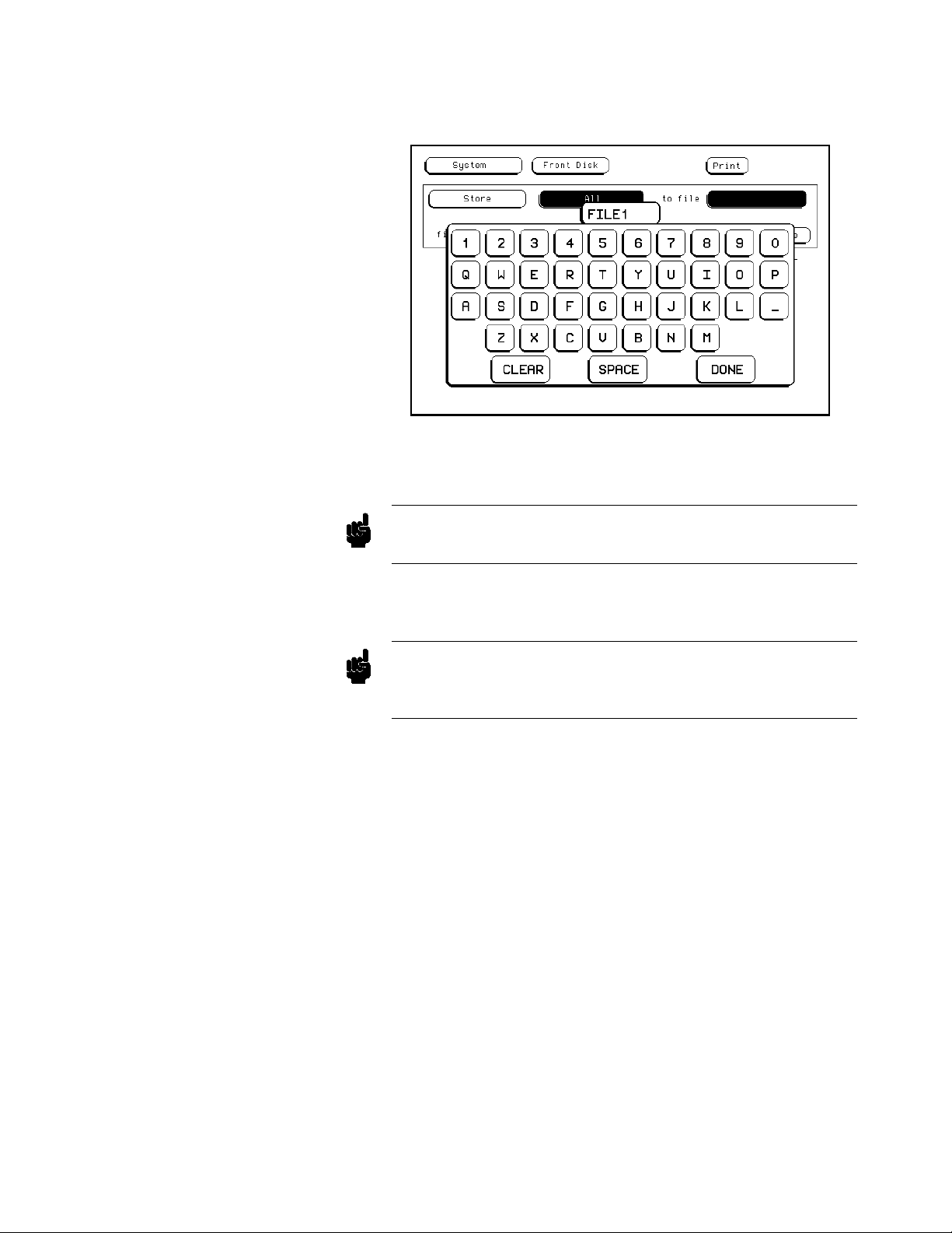
Note
3. Enter a filename that starts with a letter and contains up to eight
characters. It can be any combination of letters and numbers, b ut
there can be no blank spaces between any of the characters.
Figure 8-10. Entering a Filename.
For example, touch the appropriate keys to enter the filename “FILE1.”
If you make an error, move the cursor (with the knob) to the incorrect
character and insert the correct character with the keypad.
4. Touch Done when you are finished and the pop-up disappears,
putting FILE1_ _ to the right of “to file.”
The two spaces(_ _) after the filename designates that this file is for the
Note
The System Front and Rear Disk Menus
8-12
system. One space and a letter (_X) after the filename designates that the
file is for a specific module.
5. Touch the field to the right of “file description.”
6. When the pop-up appears, touch the appropriate keys to enter
“PRACTICE FILE” as your file description. The file description
canbeupto32charactersinlength.
Page 88
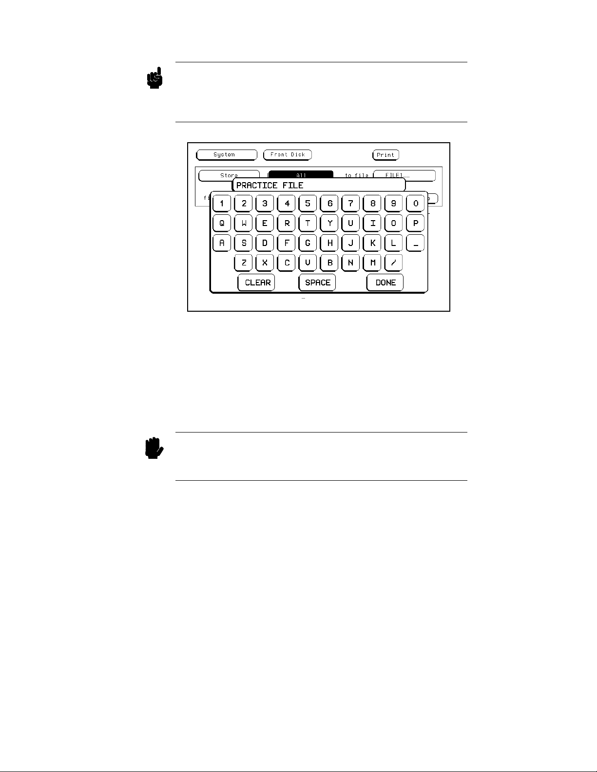
Note
The field for “file description” makes it easier to identify the type of data
in each file. This is for your convenience, but you can leave this field
blank.There is no way to change a file description after a file has been
stored.
Figure 8-11. Entering a File Description.
7. Touch Done when you are finished and the pop-up will disappear,
putting PRACTICE FILE to the right of “file description.”
Caution
8. Touch Execute to store all to FILE1.
9. When the Cancel/Continue pop-up appears, touch Continue to
continue.
If you store a new configuration and data to an existing file, the new
configuration and data are written over the original information,
DESTROYING the original information in that file.
The System Front and Rear Disk Menus
8-13
Page 89
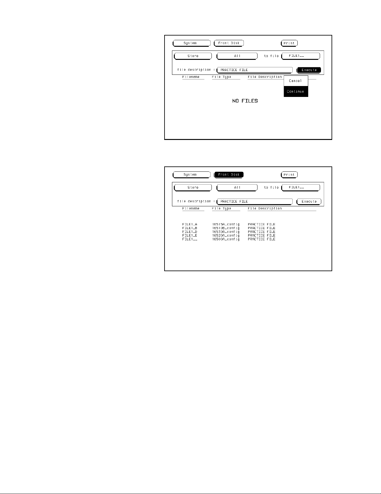
Figure 8-12. Storing a File.
Figure 8-13. Listing of the Files Stored.
When you execute the Store All operation, the HP 16500A/16501A stores
the configuration of the instrument for each module in the instrument and
for the system. The field to the right of “to file” now displays FILE1
because this was the last file stored.
In this example, five files are listed on the lower portion of the display.
The System Front and Rear Disk Menus
8-14
Page 90
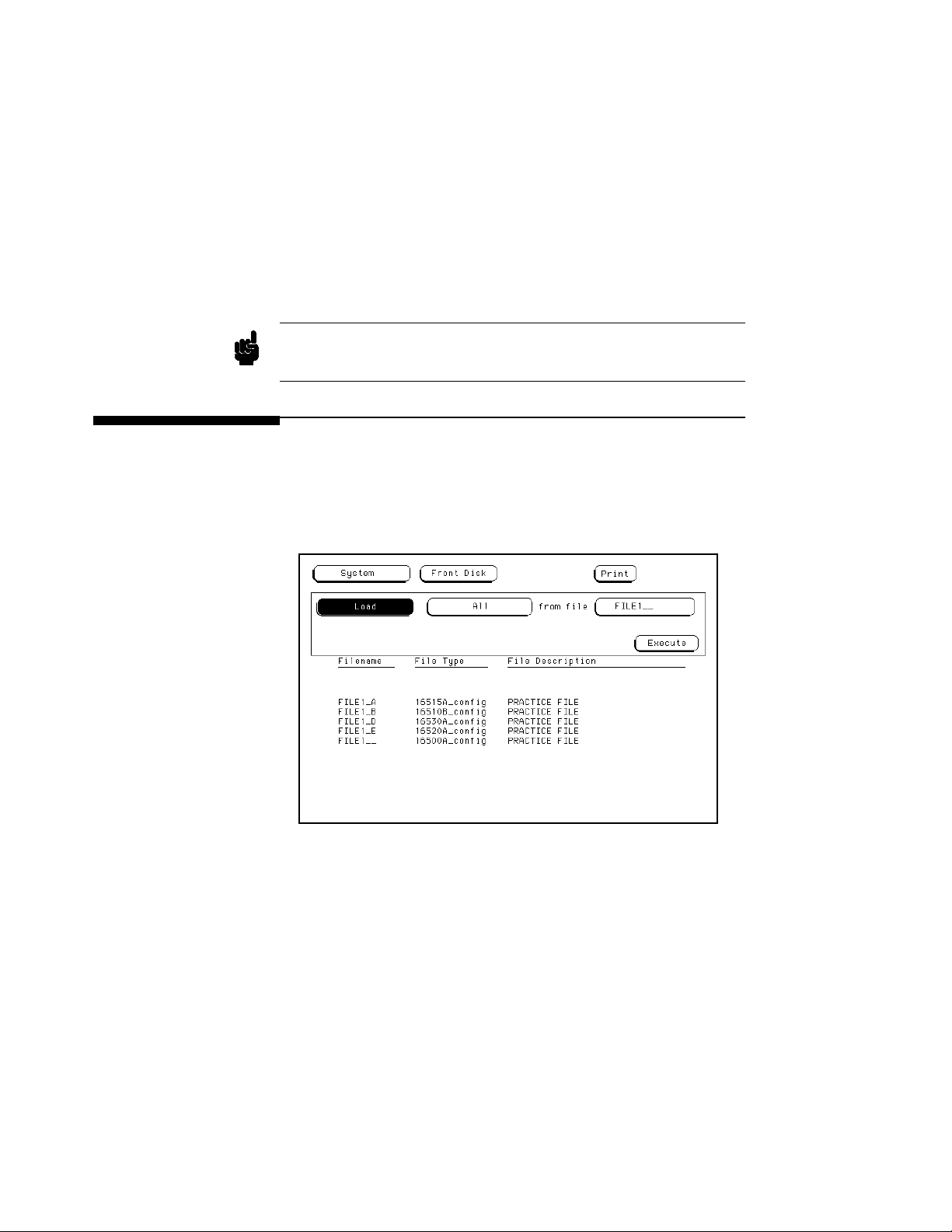
Note
• FILE1 A (type) 16515A config is for the module in slot A (the HP
16515A 1 GHz Timing module).
• FILE1 B (type) 16520A config is for the module in slot B (the HP
16520A Pattern Generator).
• FILE1 D (type) 16530A config is for the module in slot D (the HP
16530A Oscilloscope).
• FILE E (type) 16510A config is for the module in slot E (the HP
16510A State/Timing Analyzer).
• FILE1- - (type) 16500A config is for the system.
The HP 16500A/16501A system software includes the Intermodule
software.
The Load
Operation
The Load operation allows you to load all of the modules or a particular
module with previously stored configuration and data from a file on the
disk. Toload files:
1. Select the Load operation.
Figure 8-14. The Load Operation.
The System Front and Rear Disk Menus
8-15
Page 91
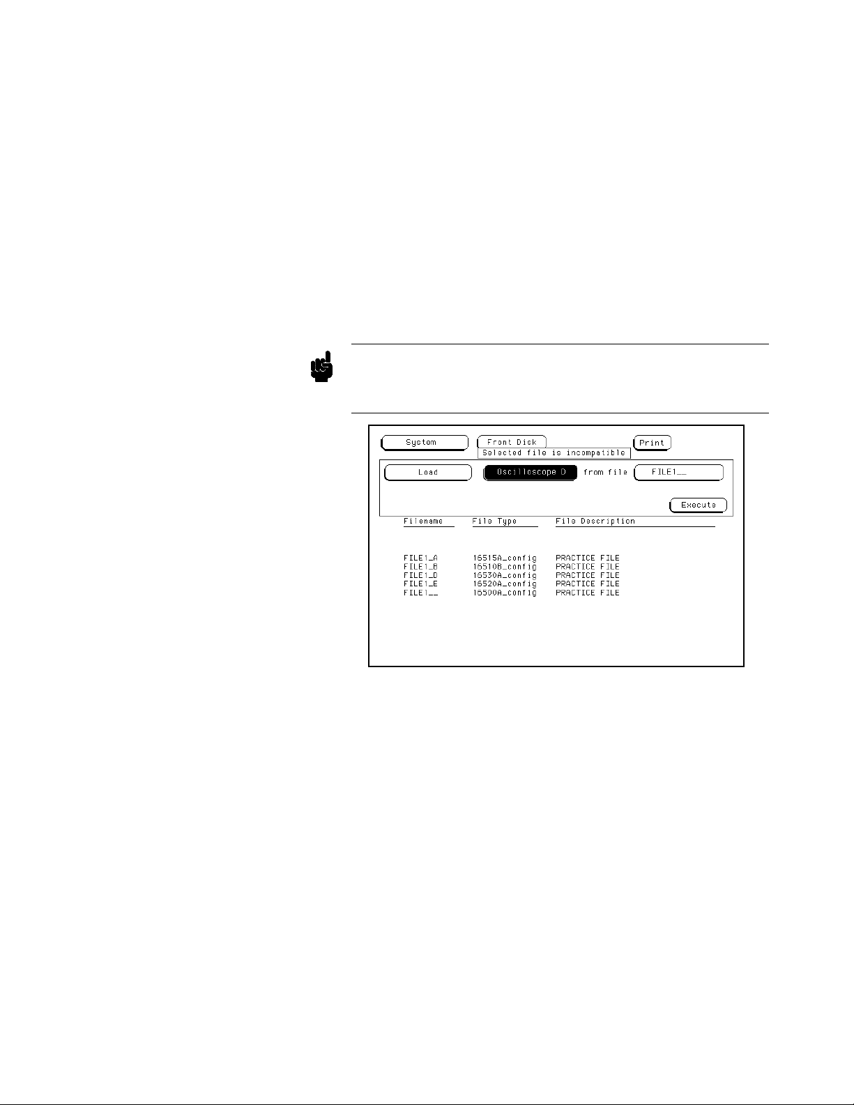
Note
2. The All fieldtotherightofLoad tells the analyzer that you want to
Load All of the modules from the file “FILE1_ _.” For this
example, load only the module in slot D (the Oscilloscope) from this
file.
Touch All and when the pop-up appears, touch the field for Oscilloscope
D. When the pop-up disappears, Oscilloscope D is displayed in the field
to the right of Load.
3. The Load operation is type dependent. This means that you cannot
load a file for one module type into a module of a different type.
For example, the screen now indicates that you want to Load the
module Oscilloscope D from FILE1. Touch Execute andanerror
message appears to indicate that FILE1_ _ is the incorrect type of
file.
The Load All operation is slot dependent. Even if the file is the right
type, the slot indicator (last letter of the filename) must match the slot
indicator of the module (last letter of the module name).
Figure 8-15. Disk Error Message.
The System Front and Rear Disk Menus
8-16
Page 92
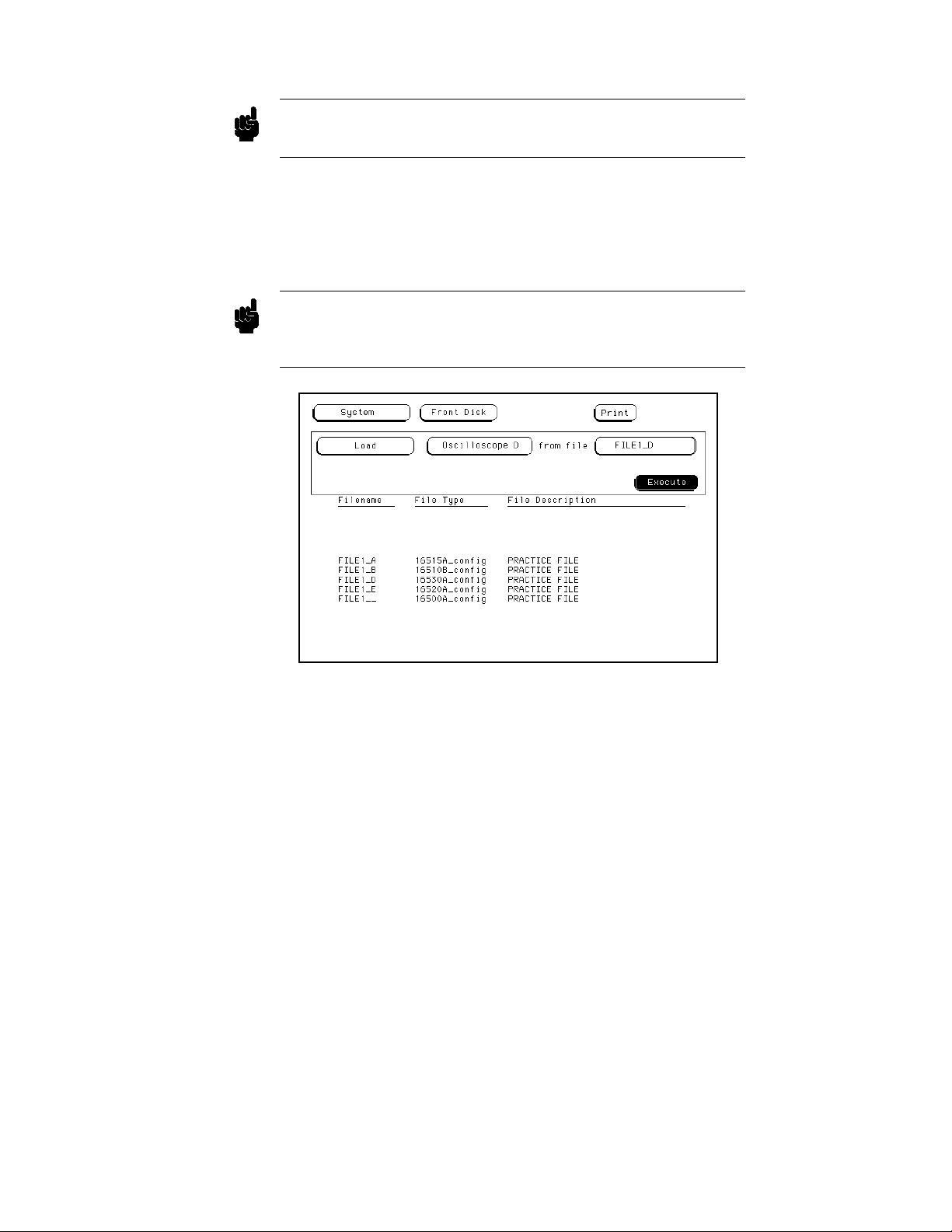
Note
Note
The compatible file types for each module are listed in the card installation
section of the reference manual for that module.
4. To correctly load the module Oscilloscope D, rotate the knob on the
front panel until FILE1_D appears in the field to the right of “from
file.” FILE1_D is for file type “16530A_config” which is a
compatible file type for this module. Touch Execute and the file is
loaded into the oscilloscope module.
Another way to enter the name of the file in the field to the right of “from
file” is to touch this field. When the pop-up keypad appears, enter the
correct filename. Touch Done when you are finished.
Figure 8-16. Loading the HP 16530A Oscilloscope.
The System Front and Rear Disk Menus
8-17
Page 93
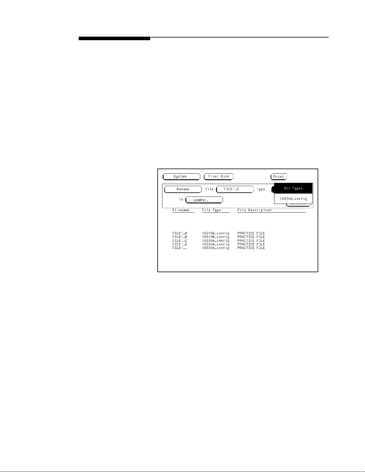
Renaming a File The Rename operation allows you to change the name of a file of a
particular type or all types to a different name. The only restriction is that
you cannot rename a file to an already existing filename. To rename a file:
1. Select the Rename operation.
2. Use either the knob or the pop-up keypad to enter a filename in the
field to the right of “file.” For this example, select FILE_D.
3. Touch the field to the right of “type” and a pop-up will appear with
the following choices:
• All Types allows you to rename all the different types of files listed
for a filename and to ignore any slot qualifications that appear in the
filename;
• “A particular file type” (16530A_config) allows only the current file
to be renamed.
Figure 8-17. Renaming a File.
The System Front and Rear Disk Menus
8-18
Page 94
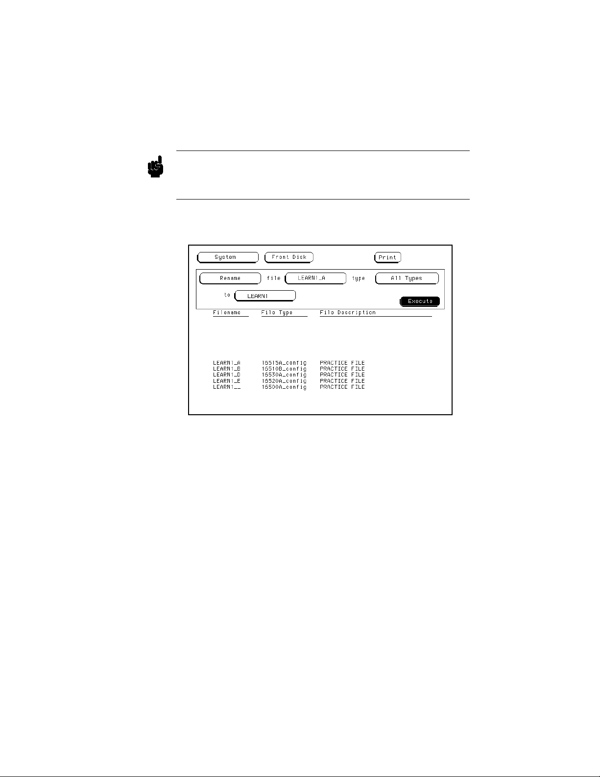
Note
4. Touch the file type you want and the pop-up disappears, displaying
your choice in the appropriate field. For this example, select All
Types.
5. Touch the field to the right of “to” and a pop-up keypad appears.
6. Enter the new name for the file with the keypad and touch Done
when you are finished. For this example, enter LEARN1.
The slot designators for the files are only preserved when copying All
Types. Otherwise, the destination file appears exactly as entered in the
destination field.
7. Touch Execute and the files are renamed LEARN1. The last file to
be renamed now appears in the field to the right of “file.”
Figure 8-18. Renaming Files Completed.
The System Front and Rear Disk Menus
8-19
Page 95
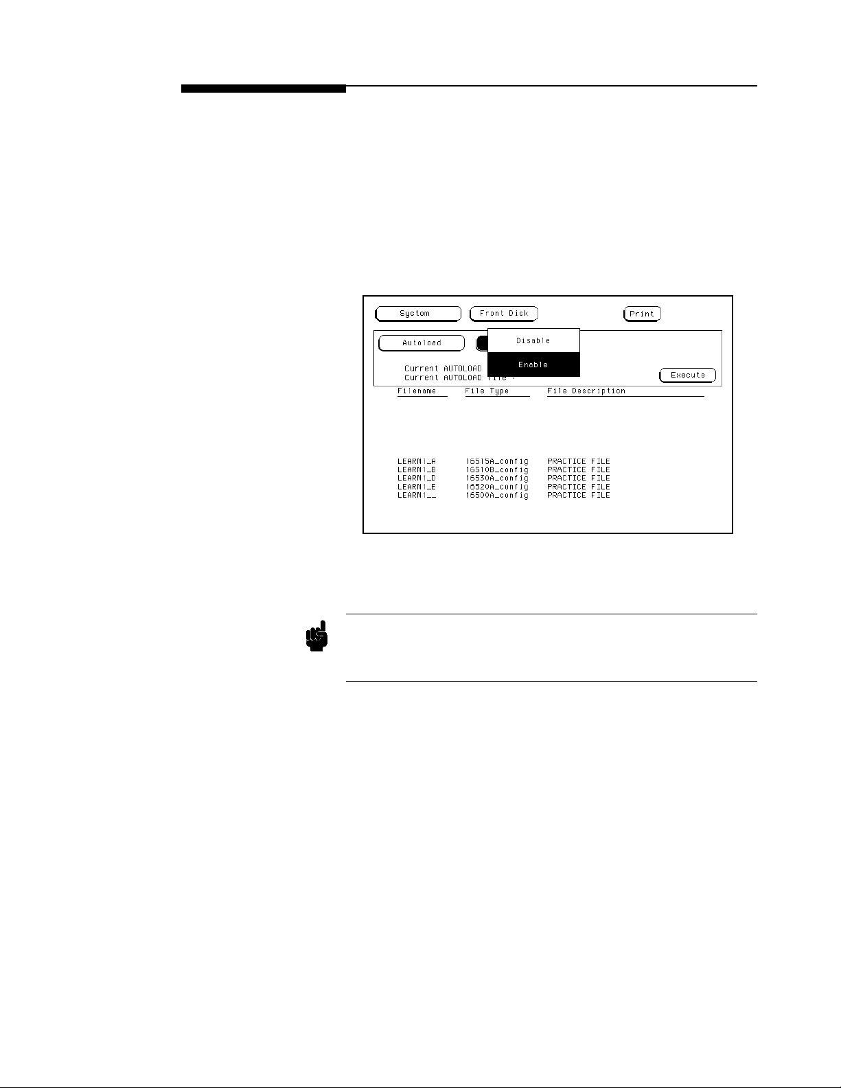
The Autoload
Operation
Autoload allows you to designate a set of configuration files to be loaded
automatically the next time the HP 16500A/16501A is turned on. This
allows you to change the default configuration of certain menus to a
configuration that better fits your needs. When the Autoload operation is
Enabled, your designated configuration file is loaded as if you had
performed a Load All. To enable the Autoload operation:
1. Select the Autoload operation.
2. Touch the Disable field and when the pop-up appears, select Enable.
3. Highlight or enter the name of your customized configuration files
Figure 8-19. Selecting Enable.
in the field to the right of “File.” For this example, enter LEARN_A.
Autoload loads all of the files for a given filename. If you want to load
Note
The System Front and Rear Disk Menus
8-20
only the file for a given module, rename that file to separate it from the
other files and enable it as the current Autoload file.
Page 96
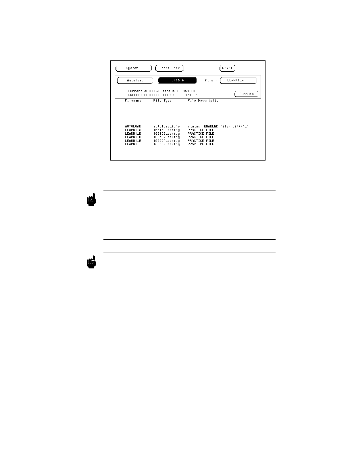
Note
4. Touch Execute and the Autoload function is Enabled as shown
after “Current AUTOLOAD status:” on the display. The question
mark (?) after the filename (LEARN_?) indicates that all files for
this given filename will be loaded when Autoload is enabled.
Figure 8-20. The Autoload Operation Enabled.
As long as Autoload is enabled before the instrument is shut off,
Autoload will remain enabled when you power-up the instrument and the
configuration files will be loaded.
Note
The “AUTOLOAD” file contains the filenames to be autoloaded and
indicates whether or not the Autoload operation is enabled.
The “Current AUTOLOAD file:” specifies a group of files.
To disable the Autoload operation:
1. Touch Enable and when the pop-up appears, touch Disable.
2. When the pop-up disappears, touch Execute and the Autoload
operation is disabled.
The System Front and Rear Disk Menus
8-21
Page 97
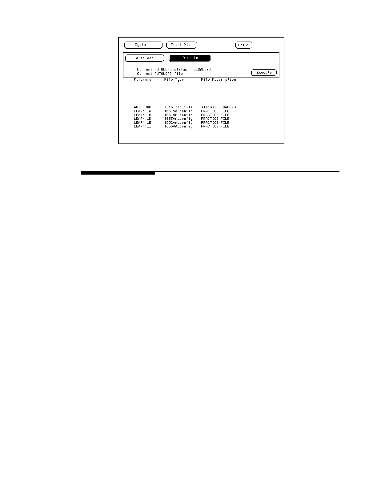
Figure 8-21. The Autoload Operation Disabled.
Purging a File Use the Purge operation to purge (delete) a file of a particular type or of
all types.
In this example, you will purge the file LEARN1_A from the disk.
1. Select the Purge operation.
2. With either the knob or the pop-up keypad enter LEARN1_A in the
fieldtotherightof“file.”
3. Touch the field to the right of “type” and when the pop-up appears,
select 16515A_config for the file type.
• All Types allows you to purge all the different types of file listed for
a filename and ignore any slot qualifications that appear in the
filename;
• “A particular file type” (16515A_config) allows only the current file
to be purged.
4. Touch Execute and when the pop-up appears, touch Continue and
notice that only the file LEARN1_A is purged from the disk.
The System Front and Rear Disk Menus
8-22
Page 98

Caution
Note
Once executed, the Purge operation permanently erases all the existing
information from the file. After that, there is no way to retrieve the
original information.
Refer to “The Pack Disk Operation” section of this chapter for information
on how and when the purged areas of a disk are used.
Figure 8-22. Purging a File.
Copying a File The Copy operation allows you to copy a file or group of files specified
on the source disk to the destination disk. To copy files:
1. Select the Copy operation.
2. With either the knob or the pop-up keypad enter the filename in the
field to the right of “file.” For example, enter LEARN1_B.
3. Touch the field to the right of “type” and a pop-up will appear with
the following choices:
The System Front and Rear Disk Menus
8-23
Page 99

Note
• All Types allows you to copy all the different types of files listed
for a filename and ignore any slot qualifications that appear in the
filename;
• “A particular file type” (16520A_config) allows only the current file
to be copied.
4. Touch the file type you want and the pop-up disappears, displaying
your choice in the appropriate field. For this example, touch
16520A_config.
5. Touch the field to the right of “to” and when the pop-up keypad
appears, enter the name of the file you want to “copy to.” For this
example, enter “NEWFILE.” After entering the filename, touch
Done.
Youcannotcopyoveranexistingfile.
6. Touch the destination field (Front Disk) to the right of “on” and
select either Front Disk or Rear Disk for the location of the
destination disk. For this example, select Front Disk.
7. Touch Execute to copy the file.
The slot designators for the files are only preserved when copying All
Note
The System Front and Rear Disk Menus
8-24
Types. Otherwise, the destination file appears exactly as entered in the
destination field.
Page 100
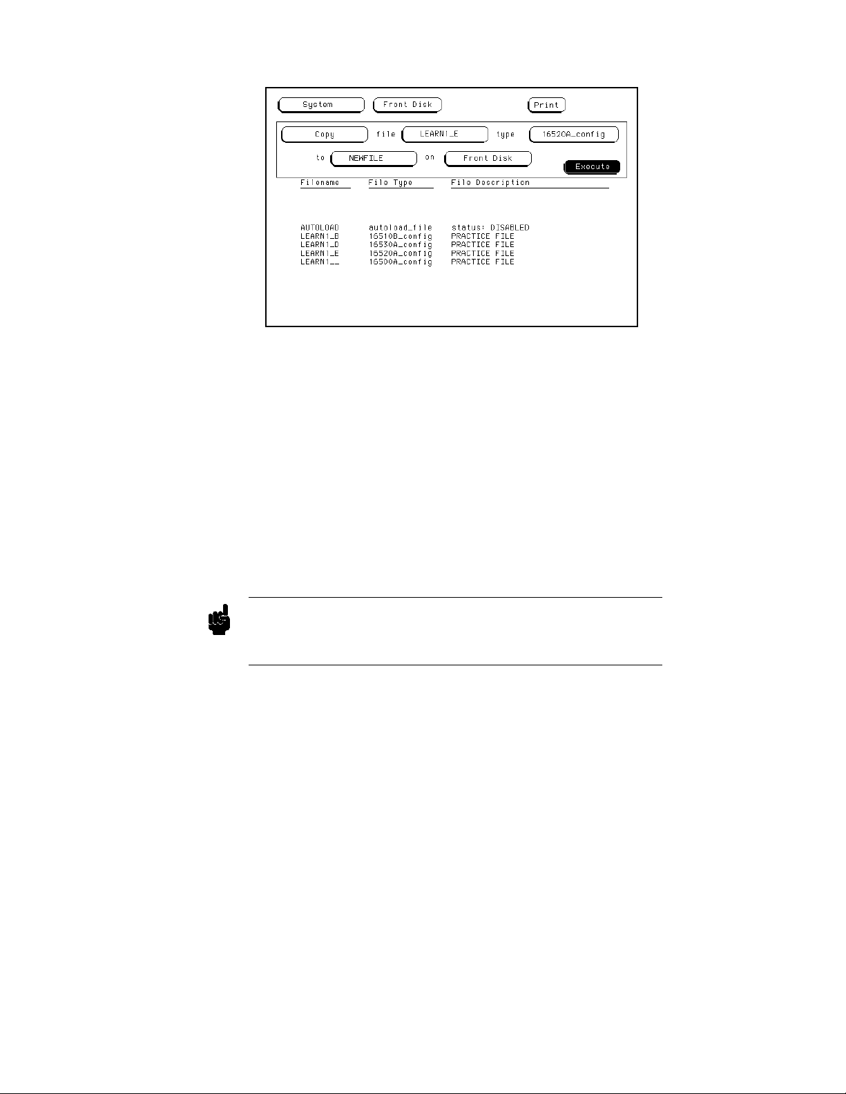
Note
Figure 8-23. Copying a File.
8. When pop-ups appear, simply follow their instructions as they apply
to your situation and touch Continue to continue.
• When “Insert DESTINATION disk” appears, insert the destination
disk into the disk drive you selected in step 6. For this example, the
original disk (source disk) is the destination disk. So when “Insert
DESTINATION disk” appears," touch Continue. No additional
prompts will appear since you did not change disks.
• If you are using separate disks for the destination and source disks
with only a single disk drive, the message “Insert SOURCE disk”
will appear. When this appears, remove the destination disk and
re-install the source disk. Then touch Continue.
You can copy across various supported formats and it is highly
recommended that you complete a Copy operation. Touching Cancel
during a Copy operation may result in a corrupted destination disk.
The System Front and Rear Disk Menus
8-25
 Loading...