


AGF Manufacturing Inc.
Pr o d u c t
In f o r m a t I o n
V008.0
Reliability, Versatility, Code Compatibility
BK002
AGF Manufacturing Inc. • Phone: 610.240.4900 • Fax: 610.240.4906 • www.testandrain.com
™
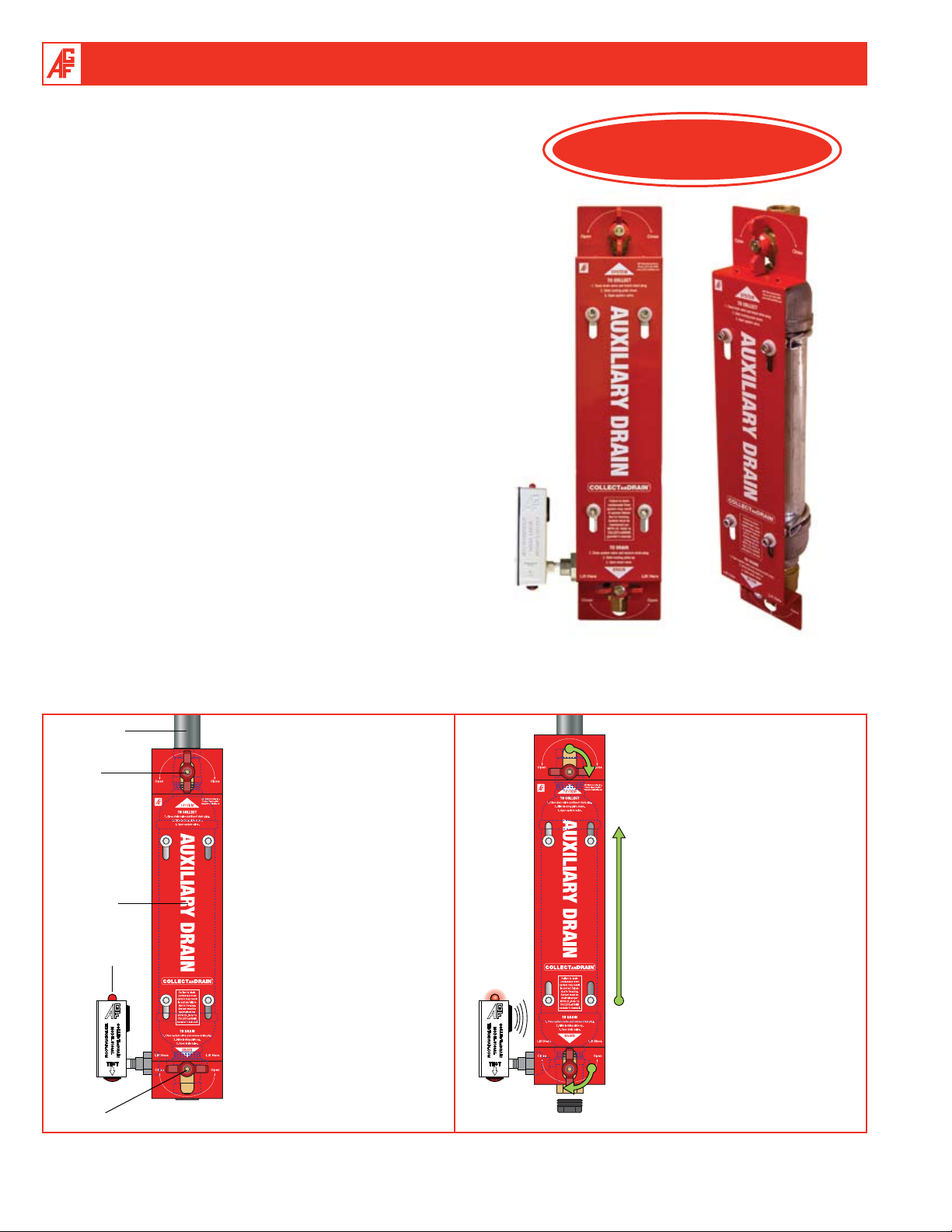
coLLEcta n draIn
The coLLEcta n draIn™ family of products are anti-trip drum drips
that prevent the accidental tripping and filling of dry pipe and pre-action
fire sprinkler systems during maintenance or as a result of vandalism.
The coLLEct
opening of either the upper or lower valve on the drum drip unless the
opposite valve is in the closed position, preventing an accidental tripping
and filling of the system and ensuring that the drum drip is operated per
NFPA 25 specifications.
The steel Anti-Trip Plate features a durable red powder coated finish that
has been silkscreened with “AUXILIARY DRAIN” for easy identification,
fulfilling NFPA signage requirements. The plate also includes operating
instructions for easy use.
The Model 5100 coLLEct
on the lower ball valve that indicates when maintenance is required.
When water is present in the drum drip, a red blinking light and beeping
alarm are activated, alerting you whenever the drum drip needs to be
drained.
A locking option is also available for added security.
The Model 5100 with alarm is available in three versions:
• Model 5100A Complete Assembly
• Model 5100K Field Assembly Kit (Includes ball valves, water detector,
and Anti-Trip Plate with mounting hardware)
• Model 5100ALBV Ball Valve with Water Detector only
The Model 5200 without alarm is available in two versions:
• Model 5200A Complete Assembly
• Model 5200K Field Assembly Kit (Includes ball valves and Anti-Trip
Plate with mounting hardware)
a n draIn’s
™
patent pending Anti-Trip Plate prevents the
a n draIn
™
includes a water detection alarm
NEW PRODUCT!
TO SYSTEM
UPPER
VALVE
ANTI-TRIP
PLATE
ALARM
LOWER
VALVE
COLLECT
COLLECTa n DRaIn™ provides
a method to drain water from
isolated sections of dry pipe and
preaction sprinkler systems that
prevents accidental discharge of
the system. When in the “COLLECT” position, the upper valve
is open and the Anti-Trip Plate is
in its lower position, preventing
the lower ball valve from being
completely opened. While in this
position, water in the system
collects in the condensate nipple.
MODEL 5100
COLLECTa n DRaIn
™
DRAIN
The alarm will blink and sound
when water has collected and
draining is required (Model 5200
only). To drain the collected water,
the upper valve must be completely
closed and the Anti-Trip Plate slid
to its upper position, allowing the
lower valve to be opened. To return
the COLLECTa n DRaIn™ to the
“COLLECT” position after draining,
the lower valve must be completely
closed and the Anti-Trip Plate slid
to its lower position for the upper
valve to be opened. This prevents
both valves from being completely
open at the same time, which could
accidentally release the air in the
system.
2
Product Information V008.0
AGF Manufacturing Inc. • Phone: 610.240.4900 • Fax: 610.240.4906 • www.testandrain.com
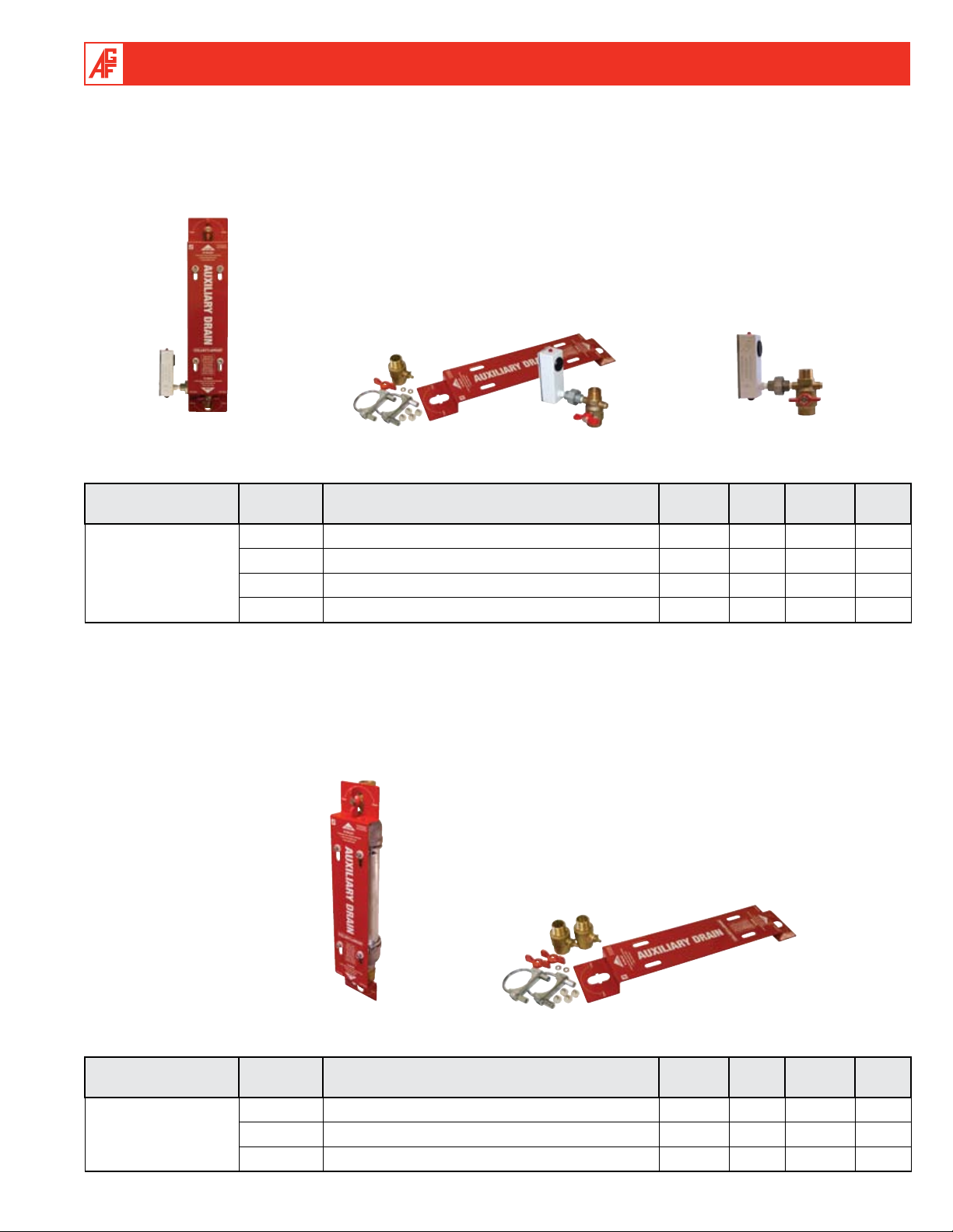
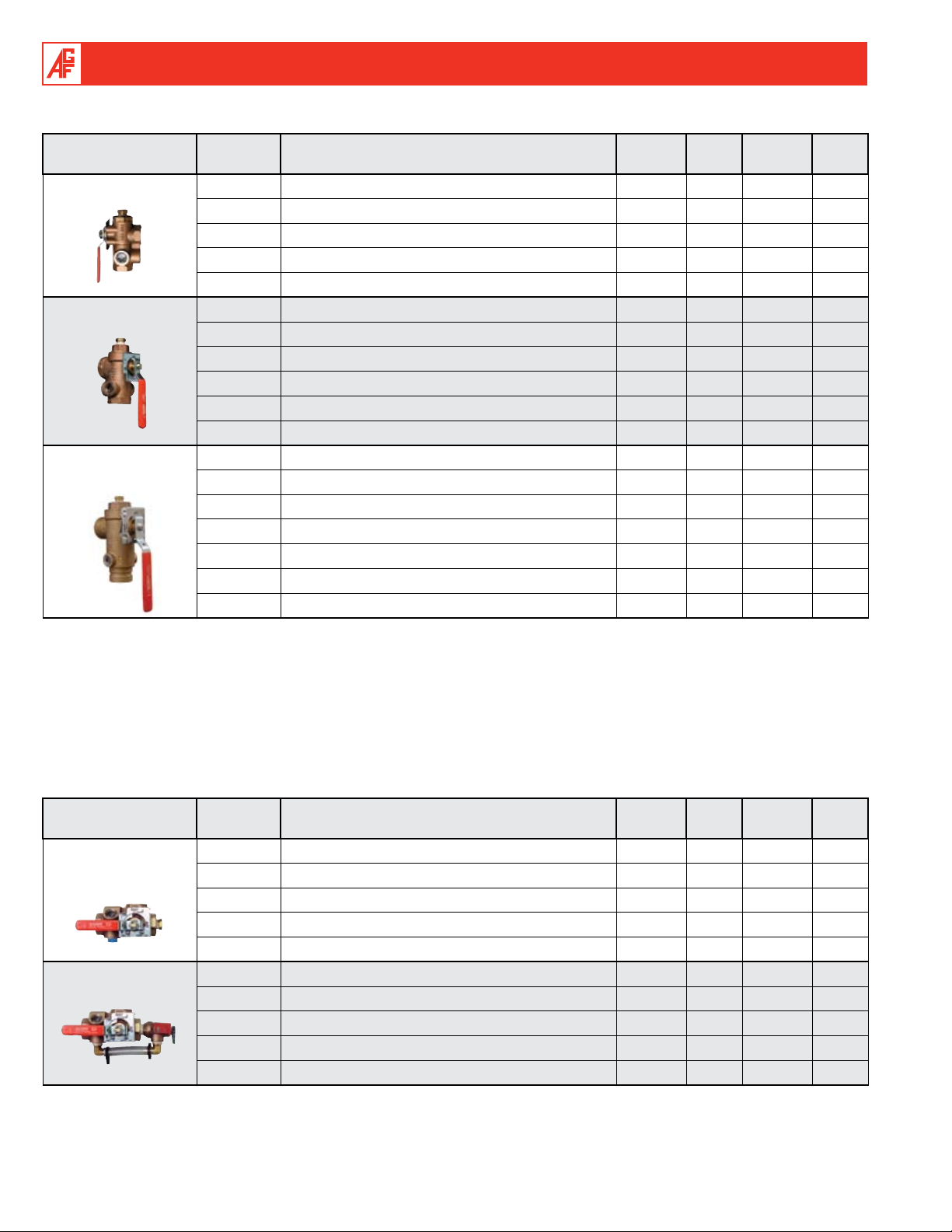
Model 5100 coLLEcta n draIn™ Anti-Trip Auxiliary Drain and Condensation Collection
Assembly with Water Detection Alarm for Dry Pipe and Preaction Fire Sprinkler Systems
Complete assembly includes pre-assembled condensation collection assembly (drum drip) with condensate nipple and reducers, 1"
ball valve, 1" M5100ALBV ball valve with water detection alarm, 1" plug, and anti-trip plate.
Field assembly kit includes 1" ball valve, 1" M5100ALBV ball valve with water detection alarm, and anti-trip plate with mounting
hardware.
Model 5100A
Complete Assembly
w/Water Detector Alarm
AGF Item ID Item Description
Model 5100K
Field Assembly Kit
w/Water Detector Alarm
Model 5100ALBV
Ball Valve w/Water Detector Alarm
Item
Class
Master
Carton
Minimum
Order Qty.
Unit
5100A M5100A Complete Assembly Special N/A 1 EACH
5100K M5100K Field Assembly Kit Special N/A 1 EACH
M5100
5100ALBV M5100ALBV Ball Valve w/Water Detector Alarm Special N/A 1 EACH
870 Optional Locking Kit Special N/A 1 EACH
Model 5200 coLLEcta n draIn™ Anti-Trip Auxiliary Drain and Condensation Collection
Assembly for Dry Pipe and Preaction Fire Sprinkler Systems
Complete assembly includes pre-assembled condensation collection assembly (drum drip) with condensate nipple and reducers,
two 1" ball valves, 1" plug, and anti-trip plate.
Field assembly kit includes two 1" ball valves and anti-trip plate with mounting hardware.
M5200
Product Information V008.0
Model 5200A
Complete Assembly
AGF Item ID Item Description
Model 5200K
Field Assembly Kit
Item
Class
Master
Carton
Minimum
Order Qty.
5200A M5200A Complete Assembly Special N/A 1 EACH
5200K M5200K Field Assembly Kit Special N/A 1 EACH
870 Optional Locking Kit Special N/A 1 EACH
Unit
3
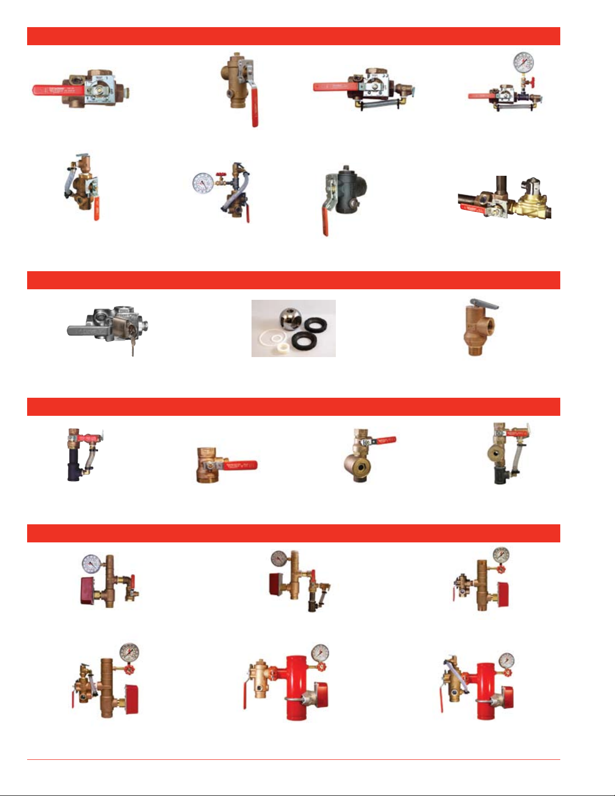
tESta n draIn
®
Model 1000
Page 5
Model 2511A
Pages 9 – 10
tESta n draIn
®
Locking Plate Kits
Page 11
In S P E c t o r ’StESt
Model 2500
Page 6
Model 2511T
Pages 9 – 10
KI t S & ac c E S S o r I E S
®
Valve Repair Kits
Page 12
Model 1011A
Pages 6 – 8
Model 1500
draIna n tESt
Page 10
Model 1011T
Pages 7 – 8
Model 1200
®
rE m o t E tESt
®
Page 11
Pressure Relief Valves & Trim Kits
Page 13
Model 3011A
Page 14
rI S E r PacK
®
Model 8000 Residential
Pages 15 – 16
Model 8011 Commercial
Bronze Riser
Pages 20 – 21
4
Model 3011BV
Page 14
Model 8011 Residential
Model 8000 Commercial
Powder Coated Steel Riser
Pages 17 – 19
Pages 21 – 22
Model 3011SG
Page 14
Model 3011ASG
Page 14
Model 8000 Commercial
Bronze Riser
Pages 19 – 20
Model 8011 Commercial
Powder Coated Steel Riser
Pages 22 – 23
Product Information V008.0
AGF Manufacturing Inc. • Phone: 610.240.4900 • Fax: 610.240.4906 • www.testandrain.com
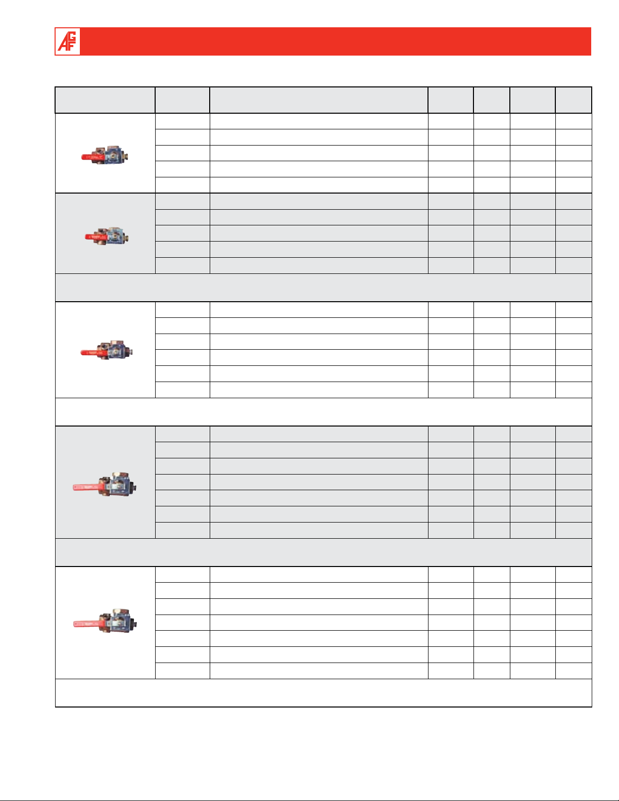
Model 1000 tESta n draIn® Sectional Floor Control Test and Drain Valve
¾" M1000
AGF Item ID Item Description
Item
Class
100 ¾" M1000 x 3⁄8" Orifice Special 10 1 EACH
Master
Carton
Minimum
Order Qty.
101 ¾" M1000 x 7⁄16" Orifice Special 10 1 EACH
102 ¾" M1000 x ½" Orifice Stock 10 1 EACH
17
⁄32" Orifice Special 10 1 EACH
5
⁄8" ELO Orifice Special 10 1 EACH
7
⁄16" Orifice Stock 10 1 EACH
1" M1000
103 ¾" M1000 x
104 ¾" M1000 x
110 1" M1000 x 3⁄8" Orifice Stock 10 1 EACH
111 1" M1000 x
112 1" M1000 x ½" Orifice Stock 10 10 EACH
17
113 1" M1000 x
⁄32" Orifice Stock 10 1 EACH
114 1" M1000 x 5⁄8" ELO Orifice Stock 10 1 EACH
NOTE: The 1" x ½" orifice Model 1000 TEST
a n DRaIn
®
Valve is available with British Standard Pipe Threads (BSPT). Please order using AGF
Item ID #412, price is the same as listed above for NPT. For 1" BSPT with orifice sizes other then ½" please call for availability.
1¼" M1000
120 1¼" M1000 x 3⁄8" Orifice Stock 10 1 EACH
7
121 1¼" M1000 x
⁄16" Orifice Stock 10 1 EACH
122 1¼" M1000 x ½" Orifice Stock 10 10 EACH
123 1¼" M1000 x 17⁄32" Orifice Stock 10 1 EACH
5
124 1¼" M1000 x
⁄8" ELO Orifice Stock 10 1 EACH
125 1¼" M1000 x ¾" ESFR Orifice Stock 10 1 EACH
NOTE: The 1¼" x ½" orifice Model 1000 TEST
a n DRaIn
®
Valve is available with British Standard Pipe Threads (BSPT). Please order using AGF
Item ID #422, price is the same as listed above for NPT. For 1¼" BSPT with orifice sizes other then ½" please call for availability.
1½" M1000
130 1½" M1000 x 3⁄8" Orifice Special 6 1 EACH
131 1½" M1000 x 7⁄16" Orifice Special 6 1 EACH
132 1½" M1000 x ½" Orifice Stock 6 1 EACH
17
133 1½" M1000 x
134 1½" M1000 x
⁄32" Orifice Special 6 1 EACH
5
⁄8" ELO Orifice Special 6 1 EACH
135 1½" M1000 x ¾" ESFR Orifice Special 6 1 EACH
136 1½" M1000 x K25 Orifice Special 6 1 EACH
NOTE: The 1½" x ½" orifice Model 1000 TEST
a n DRaIn
®
Valve is available with British Standard Pipe Threads (BSPT). Please order using AGF
Item ID #432, price is the same as listed above for NPT. For 1½" BSPT with orifice sizes other then 1/2" please call for availability.
2" M1000
140 2" M1000 x 3⁄8" Orifice Stock 6 1 EACH
141 2" M1000 x 7⁄16" Orifice Stock 6 1 EACH
142 2" M1000 x ½" Orifice Stock 6 6 EACH
17
143 2" M1000 x
144 2" M1000 x
⁄32" Orifice Stock 6 1 EACH
5
⁄8" ELO Orifice Stock 6 1 EACH
145 2" M1000 x ¾" ESFR Orifice Stock 6 1 EACH
146 2" M1000 x K25 Orifice Stock 6 1 EACH
NOTE: The 2" x ½" orifice Model 1000 TEST
a n DRaIn
®
Valve is available with British Standard Pipe Threads (BSPT). Please order using AGF
Item ID #442, price is the same as listed above for NPT. For 2" BSPT with orifice sizes other then ½" please call for availability.
Unit
Product Information V008.0
5
AGF Manufacturing Inc. • Phone: 610.240.4900 • Fax: 610.240.4906 • www.testandrain.com
Model 2500 tESta n draIn® Sectional Floor Control Test and Drain Valve
1" M2500
1¼" M2500
2" M2500
Groove x Groove
AGF Item ID Item Description
Item
Class
Master
Carton
Minimum
Order Qty.
404-0 1" M2500 x 3⁄8" Orifice Special 10 1 EACH
404-1 1" M2500 x 7⁄16" Orifice Special 10 1 EACH
404-2 1" M2500 ½" Orifice Stock 10 1 EACH
17
404-3 1" M2500
404-4 1" M2500
⁄32" Orifice Special 10 1 EACH
5
⁄8" ELO Orifice Special 10 1 EACH
405-0 1¼" M2500 x 3⁄8" Orifice Special 10 1 EACH
7
405-1 1¼" M2500 x
⁄16" Orifice Special 10 1 EACH
405-2 1¼" M2500 ½" Orifice Stock 10 1 EACH
17
405-3 1¼" M2500
⁄32" Orifice Special 10 1 EACH
405-4 1¼" M2500 5⁄8" ELO Orifice Special 10 1 EACH
405-5 1¼" M2500 ¾" ESFR Orifice Special 10 1 EACH
408-0 2" M2500 x 3⁄8" Orifice (GRV) Special 6 1 EACH
7
408-1 2" M2500 x
⁄16" Orifice (GRV) Special 6 1 EACH
408-2 2" M2500 ½" Orifice (GRV) Stock 6 1 EACH
17
408-3 2" M2500
⁄32" Orifice (GRV) Special 6 1 EACH
408-4 2" M2500 5⁄8" ELO Orifice (GRV) Special 6 1 EACH
408-5 2" M2500 ¾" ESFR Orifice (GRV) Special 6 1 EACH
408-6 2" M2500 K25 Orifice (GRV) Special 6 1 EACH
Unit
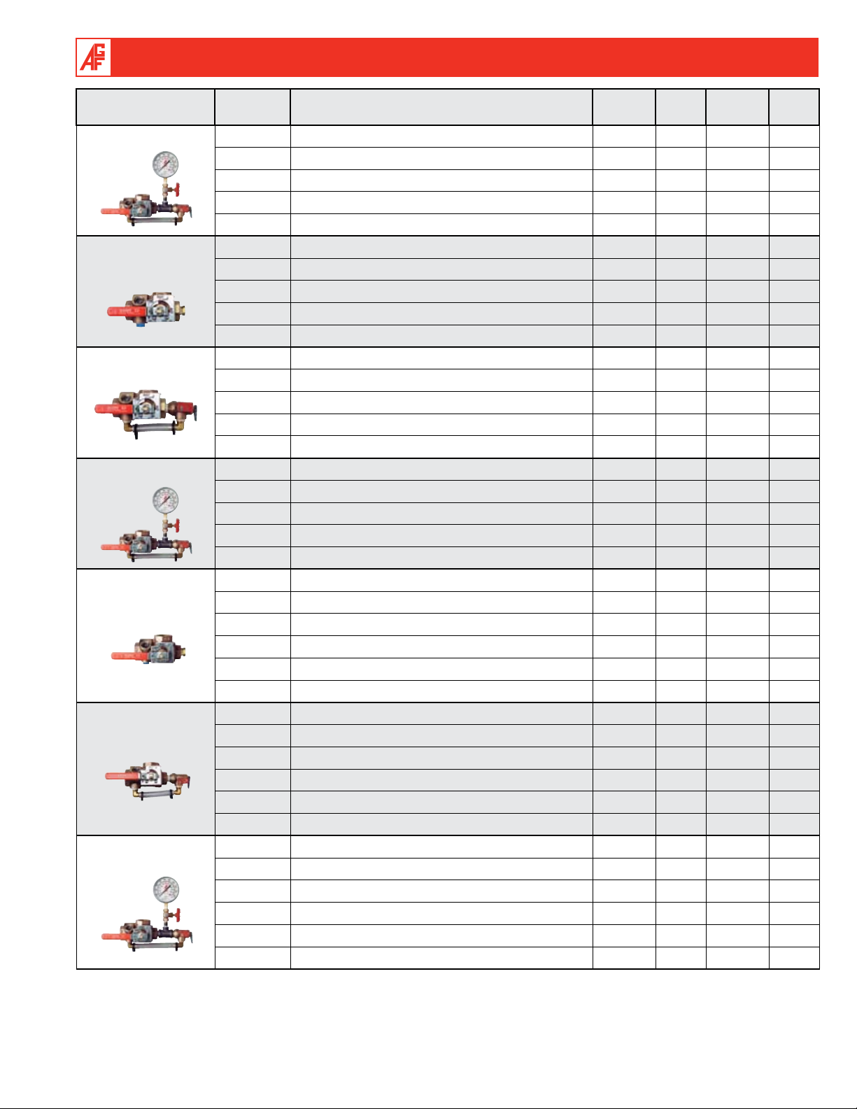
Model 1011 tESta n draIn® Sectional Floor Control Test and Drain Valve for Systems
Requiring Pressure Relief
M1011A valves are packaged with a trim kit. The trim kit includes a 175 PSI rated M7000 PRV and drain trim. M7000 valves are also
available in PSI ratings of 165, 185, 195, 205, 225 and 250.
Note: It is important to note that the pressure rating of the relief valve indicates an operating range of pressure for both opening and closing of the valve. Standard relief
valves are required to OPEN in a range of pressure between 90% and 105% of their rating. The valves are required to CLOSE at a pressure above 80% of that rating. The
relief valve should be installed where it is easily accessible for maintenance. Care should be taken that the relief valve CANNOT be isolated from the system when the
system is operational. A relief valve should NEVER have a shutoff valve or a plug downstream of its outlet.
¾" M1011
No PRV Trim
¾" M1011A
AGF Item ID Item Description
Item
Class
200 ¾" M1011 x 3⁄8" Orifice Special 10 1 EACH
7
201 ¾" M1011 x
⁄16" Orifice Special 10 1 EACH
202 ¾" M1011 x ½" Orifice Special 10 1 EACH
17
203 ¾" M1011 x
⁄32" Orifice Special 10 1 EACH
204 ¾" M1011 x 5⁄8" ELO Orifice Special 10 1 EACH
200A ¾" M1011A x 3⁄8" Orifice Special 10 1 EACH
7
201A ¾" M1011A x
⁄16" Orifice Special 10 1 EACH
202A ¾" M1011A x ½" Orifice Stock 10 1 EACH
203A ¾" M1011A x 17⁄32" Orifice Special 10 1 EACH
5
204A ¾" M1011A x
⁄8" ELO Orifice Special 10 1 EACH
Master
Carton
Minimum
Order Qty.
Unit
6
Product Information V008.0
AGF Manufacturing Inc. • Phone: 610.240.4900 • Fax: 610.240.4906 • www.testandrain.com
¾" M1011T
1" M1011
No PRV Trim
1" M1011A
1" M1011T
1¼" M1011
No PRV Trim
1¼" M1011A
1¼" M1011T
AGF Item ID Item Description
Item
Class
Master
Carton
Minimum
Order Qty.
200T ¾" M1011T x 3⁄8" Orifice Special 5 1 EACH
201T ¾" M1011T x 7⁄16" Orifice Special 5 1 EACH
202T ¾" M1011T x ½" Orifice Special 5 1 EACH
17
203T ¾" M1011T x
204T ¾" M1011T x
⁄32" Orifice Special 5 1 EACH
5
⁄8" ELO Orifice Special 5 1 EACH
210 1" M1011 x 3⁄8" Orifice Special 10 1 EACH
7
211 1" M1011 x
⁄16" Orifice Special 10 1 EACH
212 1" M1011 x ½" Orifice Special 10 1 EACH
17
213 1" M1011 x
⁄32" Orifice Special 10 1 EACH
214 1" M1011 x 5⁄8" ELO Orifice Special 10 1 EACH
210A 1" M1011A x 3⁄8" Orifice Stock 10 1 EACH
211A 1" M1011A x 7⁄16" Orifice Stock 10 1 EACH
212A 1" M1011A x ½" Orifice Stock 10 10 EACH
17
213A 1" M1011A x
214A 1" M1011A x
⁄32" Orifice Stock 10 1 EACH
5
⁄8" ELO Orifice Stock 10 1 EACH
210T 1" M1011T x 3⁄8" Orifice Special 5 1 EACH
7
211T 1" M1011T x
⁄16" Orifice Special 5 1 EACH
212T 1" M1011T x ½" Orifice Stock 5 1 EACH
17
213T 1" M1011T x
⁄32" Orifice Special 5 1 EACH
214T 1" M1011T x 5⁄8" ELO Orifice Special 5 1 EACH
220 1¼" M1011 x 3⁄8" Orifice Special 10 1 EACH
7
221 1¼" M1011 x
⁄16" Orifice Special 10 1 EACH
222 1¼" M1011 x ½" Orifice Special 10 1 EACH
223 1¼" M1011 x 17⁄32" Orifice Special 10 1 EACH
5
224 1¼" M1011 x
⁄8" ELO Orifice Special 10 1 EACH
225 1¼" M1011 x ¾" ESFR Orifice Special 10 1 EACH
220A 1¼" M1011A x 3⁄8" Orifice Stock 10 1 EACH
7
221A 1¼" M1011A x
⁄16" Orifice Stock 10 1 EACH
222A 1¼" M1011A x ½" Orifice Stock 10 10 EACH
17
223A 1¼" M1011A x
⁄32" Orifice Stock 10 1 EACH
224A 1¼" M1011A x 5⁄8" ELO Orifice Stock 10 1 EACH
225A 1¼" M1011A x ¾" ESFR Orifice Stock 10 1 EACH
220T 1¼" M1011T x 3⁄8" Orifice Special 5 1 EACH
7
221T 1¼" M1011T x
⁄16" Orifice Special 5 1 EACH
222T 1¼" M1011T x ½" Orifice Special 5 1 EACH
17
223T 1¼" M1011T x
⁄32" Orifice Special 5 1 EACH
224T 1¼" M1011T x 5⁄8" ELO Orifice Special 5 1 EACH
225T 1¼" M1011T x ¾" ESFR Orifice Special 5 1 EACH
Unit
Product Information V008.0
7
AGF Manufacturing Inc. • Phone: 610.240.4900 • Fax: 610.240.4906 • www.testandrain.com
1½" M1011
No PRV Trim
1½" M1011A
1½" M1011T
2" M1011
No PRV Trim
2" M1011A
2" M1011T
8
AGF Item ID Item Description
Item
Class
Master
Carton
Minimum
Order Qty.
230 1½" M1011 x 3⁄8" Orifice Special 6 1 EACH
231 1½" M1011 x 7⁄16" Orifice Special 6 1 EACH
232 1½" M1011 x ½" Orifice Special 6 1 EACH
17
233 1½" M1011 x
234 1½" M1011 x
⁄32" Orifice Special 6 1 EACH
5
⁄8" ELO Orifice Special 6 1 EACH
235 1½" M1011 x ¾" ESFR Orifice Special 6 1 EACH
236 1½" M1011 x K25 Orifice Special 6 1 EACH
230A 1½" M1011A x 3⁄8" Orifice Special 6 1 EACH
7
231A 1½" M1011A x
⁄16" Orifice Special 6 1 EACH
232A 1½" M1011A x ½" Orifice Stock 6 1 EACH
17
233A 1½" M1011A x
⁄32" Orifice Special 6 1 EACH
234A 1½" M1011A x 5⁄8" ELO Orifice Special 6 1 EACH
235A 1½" M1011A x ¾" ESFR Orifice Special 6 1 EACH
236A 1½" M1011A x K25 Orifice Special 6 1 EACH
230T 1½" M1011T x 3⁄8" Orifice Special 6 1 EACH
7
231T 1½" M1011T x
⁄16" Orifice Special 6 1 EACH
232T 1½" M1011T x ½" Orifice Special 6 1 EACH
233T 1½" M1011T x 17⁄32" Orifice Special 6 1 EACH
5
234T 1½" M1011T x
⁄8" ELO Orifice Special 6 1 EACH
235T 1½" M1011T x ¾" ESFR Orifice Special 6 1 EACH
236T 1½" M1011T x K25 Orifice Special 6 1 EACH
240 2" M1011 x 3⁄8" Orifice Special 6 1 EACH
241 2" M1011 x 7⁄16" Orifice Special 6 1 EACH
242 2" M1011 x ½" Orifice Special 6 1 EACH
17
243 2" M1011 x
244 2" M1011 x
⁄32" Orifice Special 6 1 EACH
5
⁄8" ELO Orifice Special 6 1 EACH
245 2" M1011 x ¾" ESFR Orifice Special 6 1 EACH
246 2" M1011 x K25 Orifice Special 6 1 EACH
240A 2" M1011A x 3⁄8" Orifice Stock 6 1 EACH
7
241A 2" M1011A x
⁄16" Orifice Stock 6 1 EACH
242A 2" M1011A x ½" Orifice Stock 6 6 EACH
17
243A 2" M1011A x
⁄32" Orifice Stock 6 1 EACH
244A 2" M1011A x 5⁄8" ELO Orifice Stock 6 1 EACH
245A 2" M1011A x ¾" ESFR Orifice Stock 6 1 EACH
246A 2" M1011A x K25 Orifice Stock 6 1 EACH
240T 2" M1011T x 3⁄8" Orifice Special 6 1 EACH
7
241T 2" M1011T x
⁄16" Orifice Special 6 1 EACH
242T 2" M1011T x ½" Orifice Special 6 1 EACH
17
243T 2" M1011T x
⁄32" Orifice Special 6 1 EACH
244T 2" M1011T x 5⁄8" ELO Orifice Special 6 1 EACH
245T 2" M1011T x ¾" ESFR Orifice Special 6 1 EACH
246T 2" M1011T x K25 Orifice Special 6 1 EACH
Product Information V008.0
Unit

AGF Manufacturing Inc. • Phone: 610.240.4900 • Fax: 610.240.4906 • www.testandrain.com
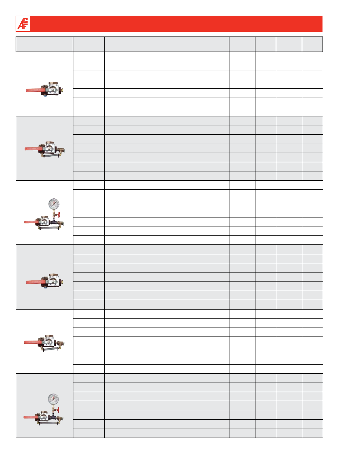
Model 2511 tESta n draIn® Sectional Floor Control Test and Drain Valve for Systems
Requiring Pressure Relief
M2511A valves are packaged with a trim kit. The trim kit includes a 175 PSI rated M7000 PRV and drain trim. M7000 valves are also
available in PSI ratings of 165, 185, 195, 205, 225, and 250.
Note: It is important to note that the pressure rating of the relief valve indicates an operating range of pressure for both opening and closing of the valve. Standard relief
valves are required to OPEN in a range of pressure between 90% and 105% of their rating. The valves are required to CLOSE at a pressure above 80% of that rating. The
relief valve should be installed where it is easily accessible for maintenance. Care should be taken that the relief valve CANNOT be isolated from the system when the
system is operational. A relief valve should NEVER have a shutoff valve or a plug downstream of its outlet.
1" M2511
No PRV Trim
1" M2511A
1" M2511T
1¼" M2511
No PRV Trim
1¼" M2511A
1¼" M2511T
AGF Item ID Item Description
Item
Class
Master
Carton
Minimum
Order Qty.
406-0 1" M2511 x 3⁄8" Orifice Special 10 1 EACH
7
406-1 1" M2511 x
⁄16" Orifice Special 10 1 EACH
406-2 1" M2511 ½" Orifice Stock 10 1 EACH
17
406-3 1" M2511
⁄32" Orifice Special 10 1 EACH
406-4 1" M2511 5⁄8" ELO Orifice Special 10 1 EACH
406A-0 1" M2511A x 3⁄8" Orifice Special 10 1 EACH
406A-1 1" M2511A x 7⁄16" Orifice Special 10 1 EACH
406A-2 1" M2511A ½" Orifice Stock 10 1 EACH
17
406A-3 1" M2511A
406A-4 1" M2511A
⁄32" Orifice Special 10 1 EACH
5
⁄8" ELO Orifice Special 10 1 EACH
406T-0 1" M2511T x 3⁄8" Orifice Special 5 1 EACH
7
406T-1 1" M2511T x
⁄16" Orifice Special 5 1 EACH
406T-2 1" M2511T ½" Orifice Stock 5 1 EACH
17
406T-3 1" M2511T
⁄32" Orifice Special 5 1 EACH
406T-4 1" M2511T 5⁄8" ELO Orifice Special 5 1 EACH
407-0 1¼" M2511 x 3⁄8" Orifice Special 10 1 EACH
407-1 1¼" M2511 x 7⁄16" Orifice Special 10 1 EACH
407-2 1¼" M2511 ½" Orifice Stock 10 1 EACH
17
407-3 1¼" M2511
407-4 1¼" M2511
⁄32" Orifice Special 10 1 EACH
5
⁄8" ELO Orifice Special 10 1 EACH
407-5 1¼" M2511 x ¾" ESFR Orifice Special 10 1 EACH
407A-0 1¼" M2511A x 3⁄8" Orifice Special 10 1 EACH
7
407A-1 1¼" M2511A x
⁄16" Orifice Special 10 1 EACH
407A-2 1¼" M2511A ½" Orifice Stock 10 1 EACH
17
407A-3 1¼" M2511A
⁄32" Orifice Special 10 1 EACH
407A-4 1¼" M2511A 5⁄8" ELO Orifice Special 10 1 EACH
407A-5 1¼" M2511A x ¾" ESFR Orifice Special 10 1 EACH
407T-0 1¼" M2511T x 3⁄8" Orifice Special 5 1 EACH
7
407T-1 1¼" M2511T x
⁄16" Orifice Special 5 1 EACH
407T-2 1¼" M2511T ½" Orifice Stock 5 1 EACH
17
407T-3 1¼" M2511T
⁄32" Orifice Special 5 1 EACH
407T-4 1¼" M2511T 5⁄8" ELO Orifice Special 5 1 EACH
407T-5 1¼" M2511T x ¾" ESFR Orifice Special 5 1 EACH
Unit
Product Information V008.0
9

AGF Manufacturing Inc. • Phone: 610.240.4900 • Fax: 610.240.4906 • www.testandrain.com
2" M2511
No PRV Trim
Groove x Groove
2" M2511A
Groove x Groove
2" M2511T
Groove x Groove
AGF Item ID Item Description
Item
Class
Master
Carton
Minimum
Order Qty.
409-0 2" M2511 x 3⁄8" Orifice (GRV) Special 6 1 EACH
409-1 2" M2511 x 7⁄16" Orifice (GRV) Special 6 1 EACH
409-2 2" M2511 ½" Orifice (GRV) Stock 6 1 EACH
17
409-3 2" M2511
409-4 2" M2511
⁄32" Orifice (GRV) Special 6 1 EACH
5
⁄8" ELO Orifice (GRV) Special 6 1 EACH
409-5 2" M2511 ¾" ESFR Orifice (GRV) Special 6 1 EACH
409-6 2" M2511 K25 Orifice (GRV) Special 6 1 EACH
409A-0 2" M2511A x 3⁄8" Orifice (GRV) Special 6 1 EACH
7
409A-1 2" M2511A x
⁄16" Orifice (GRV) Special 6 1 EACH
409A-2 2" M2511A ½" Orifice (GRV) Stock 6 1 EACH
17
409A-3 2" M2511A
⁄32" Orifice (GRV) Special 6 1 EACH
409A-4 2" M2511A 5⁄8" ELO Orifice (GRV) Special 6 1 EACH
409A-5 2" M2511A ¾" ESFR Orifice (GRV) Special 6 1 EACH
409A-6 2" M2511A K25 Orifice (GRV) Special 6 1 EACH
409T-0 2" M2511T x 3⁄8" Orifice (GRV) Special 6 1 EACH
7
409T-1 2" M2511T x
⁄16" Orifice (GRV) Special 6 1 EACH
409T-2 2" M2511T ½" Orifice (GRV) Special 6 1 EACH
409T-3 2" M2511T 17⁄32" Orifice (GRV) Special 6 1 EACH
5
409T-4 2" M2511T
⁄8" ELO Orifice (GRV) Special 6 1 EACH
409T-5 2" M2511T ¾" ESFR Orifice (GRV) Special 6 1 EACH
409T-6 2" M2511T K25 Orifice (GRV) Special 6 1 EACH
Unit
Model 1500 DRAINa n tESt® Alarm Main Drain and Test Valve
Iron Body without Sight Glasses
AGF Item ID Item Description
2" BSPT M1500
290 2" BSPT M1500 x 3⁄8" Orifice Special 6 1 EACH
291 2" BSPT M1500 x 7⁄16" Orifice Special 6 1 EACH
292 2" BSPT M1500 x ½" Orifice Special 6 6 EACH
17
293 2" BSPT M1500 x
⁄32" Orifice Special 6 1 EACH
294 2" BSPT M1500 x 5⁄8" ELO Orifice Special 6 1 EACH
295 2" BSPT M1500 x ¾" ESFR Orifice Special 6 1 EACH
296 2" BSPT M1500 x K25 Orifice Special 6 1 EACH
Item
Class
Master
Carton
Minimum
Order Qty.
Unit
10
Product Information V008.0

AGF Manufacturing Inc. • Phone: 610.240.4900 • Fax: 610.240.4906 • www.testandrain.com
Model 1200 rE m o t E tESt® Remote
Operated tESt
Energizing the solenoid incorporated into the TESTa n DRaIn® valve
allows system water to flow through a test orifice. After the preset
time delay, the water flow alarm is activated confirming system
integrity. R
panel or wired to an independent panel, allowing ONE person to
activate each specific system or a group of systems from ONE
central location. An optional bypass drain loop kit is also available.
E m o T E TEST
a n draIn
®
is designed to be integrated into an existing
®
Valve
With Optional Bypass
Drain Loop Kit
1" M1200
1¼" M1200
1½" M1200
2" M1200
Bypass Kit
AGF Item ID Item Description
Item
Class
Master
Carton
Minimum
Order Qty.
270-350 1" M1200 x ½" Orifice w/1" Solenoid Valve 24V Special 1 1 EACH
270-351 1" M1200 x ½" Orifice w/1" Solenoid Valve 110V Special 1 1 EACH
3
Note: Other orifice sizes are also available (
⁄8", 7⁄16", 17⁄32", 5⁄8" ELO)
272-350 1¼" M1200 x ½" Orifice w/1" Solenoid Valve 24V Special 1 1 EACH
272-351 1¼" M1200 x ½" Orifice w/1" Solenoid Valve 110V Special 1 1 EACH
3
Note: Other orifice sizes are also available (
Special
Order
Special
Order
1½" M1200 x ½" Orifice w/1" Solenoid Valve 24V Special 1 1 EACH
1½" M1200 x ½" Orifice w/1" Solenoid Valve 110V Special 1 1 EACH
Note: Other orifice sizes are also available (
⁄8", 7⁄16", 17⁄32", 5⁄8" ELO, ¾" ESFR)
3
⁄8", 7⁄16", 17⁄32", 5⁄8" ELO, ¾" ESFR)
274-350 2" M1200 x ½" Orifice w/1" Solenoid Valve 24V Special 1 1 EACH
274-351 2" M1200 x ½" Orifice w/1" Solenoid Valve 110V Special 1 1 EACH
3
Note: Other orifice sizes are also available (
⁄8", 7⁄16", 17⁄32", 5⁄8" ELO, ¾" ESFR, K25)
365 Model 1200 1" Bypass Kit Special 1 1 EACH
365 Model 1200 1¼" Bypass Kit Special 1 1 EACH
365 Model 1200 1½" Bypass Kit Special 1 1 EACH
365 Model 1200 2" Bypass Kit Special 1 1 EACH
Unit
Locking Plate Kits
Provide protection and vandal-resistance for Models 1000, 1011,
2500, 2511 TESTa n DRan®, Model 1200 RE m o T E TEST®, and Model
1500 DRaIna n TEST®. Includes locking plate, hex key, lock, and (2)
keys. Please indicate valve size when ordering.
AGF Item ID Item Description
Locking Plate Kit
Product Information V008.0
870 Locking Plate Kit (Specify Valve Size When Ordering) Special 1 1 EACH
Item
Class
Master
Carton
Minimum
Order Qty.
Unit
11

AGF Manufacturing Inc. • Phone: 610.240.4900 • Fax: 610.240.4906 • www.testandrain.com
Valve Repair Kits
Repair kits are available for all Models 1000, 1011, 2500, 2511 TESTa n DRaIn®;
1200 RE m o T E TEST®; and 1500 DRaIna n TEST® valves. Repair kits include: (1)
replacement adapter gasket, (1) replacement ball, (2) replacement valve seats,
(1) replacement stem packing, and (1) replacement stem washer. For more
information visit testandrain.com and click on the “SUPPORT” button.
Repair Kit for ¾"
and 1" Models
1000, 1011, 1200
Repair Kit for 1¼"
Models 1000,
1011, 1200
Repair Kit for 1½"
and 2" Models
1000, 1011, 1200
Repair Kit for 1"
Models 2500, 2511
Repair Kit for 1¼"
Models 2500, 2511
Repair Kit for 2"
Models 2500,
2511, 1500
AGF Item ID Item Description
Item
Class
Master
Carton
Minimum
Order Qty.
9700A Repair Kit for ¾" and 1" Valves; 3⁄8" Orifice Assembly 1 1 EACH
7
9701A Repair Kit for ¾" and 1" Valves;
⁄16" Orifice Assembly 1 1 EACH
9702A Repair Kit for ¾" and 1" Valves; ½" Orifice Assembly 1 1 EACH
17
9703A Repair Kit for ¾" and 1" Valves;
⁄32" Orifice Assembly 1 1 EACH
9704A Repair Kit for ¾" and 1" Valves; 5⁄8" ELO Orifice Assembly 1 1 EACH
9710A Repair Kit for 1¼" Valves; 3⁄8" Orifice Assembly 1 1 EACH
7
9711A Repair Kit for 1¼" Valves;
⁄16" Orifice Assembly 1 1 EACH
9712A Repair Kit for 1¼" Valves; ½" Orifice Assembly 1 1 EACH
17
9713A Repair Kit for 1¼" Valves;
⁄32" Orifice Assembly 1 1 EACH
9714A Repair Kit for 1¼" Valves; 5⁄8" ELO Orifice Assembly 1 1 EACH
9715A Repair Kit for 1¼" Valves;
¾" ESFR Orifice Assembly 1 1 EACH
9730A Repair Kit for 1½" and 2" Valves; 3⁄8" Orifice Assembly 1 1 EACH
7
9731A Repair Kit for 1½" and 2" Valves;
⁄16" Orifice Assembly 1 1 EACH
9732A Repair Kit for 1½" and 2" Valves; ½" Orifice Assembly 1 1 EACH
17
9733A Repair Kit for 1½" and 2" Valves;
9734A Repair Kit for 1½" and 2" Valves;
⁄32" Orifice Assembly 1 1 EACH
5
⁄8" ELO Orifice Assembly 1 1 EACH
9735A Repair Kit for 1½" and 2" Valves; ¾" ESFR Orifice Assembly 1 1 EACH
9736A Repair Kit for 1½" and 2" Valves; K25 Orifice Assembly 1 1 EACH
9741A Repair Kit for 1" Valves; 3⁄8" Orifice Assembly 1 1 EACH
7
9742A Repair Kit for 1" Valves;
⁄16" Orifice Assembly 1 1 EACH
9743A Repair Kit for 1" Valves; ½" Orifice Assembly 1 1 EACH
17
9744A Repair Kit for 1" Valves;
9745A Repair Kit for 1" Valves;
⁄32" Orifice Assembly 1 1 EACH
5
⁄8" ELO Orifice Assembly 1 1 EACH
9750A Repair Kit for 1¼" Valves; 3⁄8" Orifice Assembly 1 1 EACH
7
9751A Repair Kit for 1¼" Valves;
⁄16" Orifice Assembly 1 1 EACH
9752A Repair Kit for 1¼" Valves; ½" Orifice Assembly 1 1 EACH
17
9753A Repair Kit for 1¼" Valves;
⁄32" Orifice Assembly 1 1 EACH
9754A Repair Kit for 1¼" Valves; 5⁄8" ELO Orifice Assembly 1 1 EACH
9755A Repair Kit for 1¼" Valves;
¾" ESFR Orifice Assembly 1 1 EACH
9760A Repair Kit for 2" Valves; 3⁄8" Orifice Assembly 1 1 EACH
7
9761A Repair Kit for 2" Valves;
⁄16" Orifice Assembly 1 1 EACH
9762A Repair Kit for 2" Valves; ½" Orifice Assembly 1 1 EACH
17
9763A Repair Kit for 2" Valves;
9764A Repair Kit for 2" Valves;
⁄32" Orifice Assembly 1 1 EACH
5
⁄8" ELO Orifice Assembly 1 1 EACH
9765A Repair Kit for 2" Valves; ¾" ESFR Orifice Assembly 1 1 EACH
9766A Repair Kit for 2" Valves; K25 Orifice Assembly 1 1 EACH
Unit
12
Product Information V008.0

AGF Manufacturing Inc. • Phone: 610.240.4900 • Fax: 610.240.4906 • www.testandrain.com
Model 1011 Kits - Pressure Relief Valve Trim Kits
Pressure relief valve and trim kits for Model 1000 and 2500 TESTa n DRaIn® and Model 1500 DRaIna n TEST® include M7000 pressure
relief valve, bypass tubing, (2) barbed elbows, and (2) hose clamps. 1011T kits also include M7500 pressure gauge, M7600 3-way
globe valve, and (2) nipples. Kits are shipped with 175PSI rated relief valve standard. Other PSI options are available (165, 185, 195,
205, 225, 250) and may be exchanged at no additional charge.
Note: It is important to note that the pressure rating of the relief valve indicates an operating range of pressure for both opening and closing of the valve. Standard relief
valves are required to OPEN in a range of pressure between 90% and 105% of their rating. The valves are required to CLOSE at a pressure above 80% of that rating. The
relief valve should be installed where it is easily accessible for maintenance. Care should be taken that the relief valve CANNOT be isolated from the system when the
system is operational. A relief valve should NEVER have a shutoff valve or a plug downstream of its outlet.
M1011 Kit
AGF Item ID Item Description
Item
Class
260 Model 1011 ¾" Kit Parts Kit 1 1 EACH
Master
Carton
Minimum
Order Qty.
Unit
260 Model 1011 1" Kit Parts Kit 1 1 EACH
261 Model 1011 1¼" Kit Parts Kit 1 1 EACH
262 Model 1011 1½" Kit Parts Kit 1 1 EACH
262 Model 1011 2" Kit Parts Kit 1 1 EACH
M1011T Kit
263 Model 1011T ¾" Kit Parts Kit 1 1 EACH
263 Model 1011T 1" Kit Parts Kit 1 1 EACH
264 Model 1011T 1¼" Kit Parts Kit 1 1 EACH
265 Model 1011T 1½" Kit Parts Kit 1 1 EACH
265 Model 1011T 2" Kit Parts Kit 1 1 EACH
Model 7000 Pressure Relief Valve - 7500 Gauge - 7600 Gauge Valve
Note: It is important to note that the pressure rating of the relief valve indicates an operating range of pressure for both opening and closing of the valve. Standard relief
valves are required to OPEN in a range of pressure between 90% and 105% of their rating. The valves are required to CLOSE at a pressure above 80% of that rating. The
relief valve should be installed where it is easily accessible for maintenance. Care should be taken that the relief valve CANNOT be isolated from the system when the
system is operational. A relief valve should NEVER have a shutoff valve or a plug downstream of its outlet.
M7000 / M7200
AGF Item ID Item Description
Item
Class
600 M7000 ½" Relief Valve 175PSI Stock 50 50 EACH
601 M7000 ½" Relief Valve 165PSI Stock 50 1 EACH
602 M7000 ½" Relief Valve 185PSI Stock 50 1 EACH
603 M7000 ½" Relief Valve 195PSI Stock 50 1 EACH
605 M7000 ½" Relief Valve 205PSI Stock 50 1 EACH
606 M7000 ½" Relief Valve 225PSI Stock 50 1 EACH
607 M7000 ½" Relief Valve 250PSI Stock 50 1 EACH
604 Special Relief Valve Stock 25 1 EACH
610 M7200 ¾" Relief Valve Stock 50 1 EACH
Master
Carton
Minimum
Order Qty.
Unit
M7500 M7600
Product Information V008.0
650 M7500 3½" Pressure Gauge Stock 60 1 EACH
660 M7600 ¼" 3-Way Globe Valve Stock 100 1 EACH
13

AGF Manufacturing Inc. • Phone: 610.240.4900 • Fax: 610.240.4906 • www.testandrain.com
Model 3011 In S P E c t o r S tESt® Connection for Single Story and Other Applications
M3011A and M3011ASG valves are packaged with a trim kit. The trim kit includes a 175 PSI rated M7000 PRV and drain trim.
M7000 valves are also available in PSI ratings of 165, 185, 195, 205, 225, 250.
Note: It is important to note that the pressure rating of the relief valve indicates an operating range of pressure for both opening and closing of the valve. Standard relief
valves are required to OPEN in a range of pressure between 90% and 105% of their rating. The valves are required to CLOSE at a pressure above 80% of that rating. The
relief valve should be installed where it is easily accessible for maintenance. Care should be taken that the relief valve CANNOT be isolated from the system when the
system is operational. A relief valve should NEVER have a shutoff valve or a plug downstream of its outlet.
M3011A
M3011BV
M3011SG
M3011ASG
M3011
Accessories
AGF Item ID Item Description
Item
Class
Master
Carton
Minimum
Order Qty.
300A M3011A x 3⁄8" Orifice Stock 10 1 EACH
301A M3011A x 7⁄16" Orifice Stock 10 1 EACH
302A M3011A x ½" Orifice Stock 10 10 EACH
17
303A M3011A x
304A M3011A x
⁄32" Orifice Stock 10 1 EACH
5
⁄8" ELO Orifice Stock 10 1 EACH
300BV M3011BV x 3⁄8" Orifice Stock 10 1 EACH
7
301BV M3011BV x
⁄16" Orifice Stock 10 1 EACH
302BV M3011BV x ½" Orifice Stock 10 1 EACH
17
303BV M3011BV x
⁄32" Orifice Stock 10 1 EACH
304BV M3011BV x 5⁄8" ELO Orifice Stock 10 1 EACH
300SG M3011SG x 3⁄8" Orifice Special 10 1 EACH
7
301SG M3011SG x
⁄16" Orifice Special 10 1 EACH
302SG M3011SG x ½" Orifice Special 10 1 EACH
17
303SG M3011SG x
⁄32" Orifice Special 10 1 EACH
304SG M3011SG x 5⁄8" ELO Orifice Special 10 1 EACH
300ASG M3011ASG x 3⁄8" Orifice Special 10 1 EACH
301ASG M3011ASG x 7⁄16" Orifice Special 10 1 EACH
302ASG M3011ASG x ½" Orifice Special 10 1 EACH
17
303ASG M3011ASG x
304ASG M3011ASG x
⁄32" Orifice Special 10 1 EACH
5
⁄8" ELO Orifice Special 10 1 EACH
305 M3011 1" Sight Glass Stock 1 1 EACH
306 Model 3011 1" Kit Assembly 1 1 EACH
Unit
14
Product Information V008.0

AGF Manufacturing Inc. • Phone: 610.240.4900 • Fax: 610.240.4906 • www.testandrain.com
N
e
w
N
o
s
.
Model 8000 rE S I d E n t I a L rI S E r PacK® Pre Assembled Riser for NFPA 13D Systems
Assembly includes: bronze riser body w/ imprinted signage, water flow alarm switch w/ retard, 3½" pressure gauge, appropriately
sized drain valve w/ specific TEST orifice, sight glass option available, non retard flow switch special order
1" M8000
Thread
1¼" M8000
Thread
1½" M8000
Thread
1½" M8000
Thread x Groove
1½" M8000
Groove
2" M8000
Thread
2" M8000
Thread x Groove
2" M8000
Groove
AGF Item ID Item Description
Item
Class
Master
Carton
Minimum
Order Qty.
8100D 1" M8000 x 3.0k-A Orifice Assembly 1 1 EACH
8101D 1" M8000 x 3.7k-B Orifice Assembly 1 1 EACH
8102D 1" M8000 x 4.3k-C Orifice Assembly 1 1 EACH
8103D 1" M8000 x 5.5k-D Orifice Assembly 1 1 EACH
8110D 1¼" M8000 x 3⁄8" Orifice Assembly 1 1 EACH
8111D 1¼" M8000 x 7⁄16" Orifice Assembly 1 1 EACH
8112D 1¼" M8000 x ½" Orifice Assembly 1 1 EACH
17
8113D 1¼" M8000 x
⁄32" Orifice Assembly 1 1 EACH
8114D 1¼" M8000 x 5⁄8" ELO Orifice Assembly 1 1 EACH
8120D 1½" M8000 (THD) x 3⁄8" Orifice Assembly 1 1 EACH
8121D 1½" M8000 (THD) x 7⁄16" Orifice Assembly 1 1 EACH
8122D 1½" M8000 (THD) x ½" Orifice Assembly 1 1 EACH
17
8123D 1½" M8000 (THD) x
8124D 1½" M8000 (THD) x
⁄32" Orifice Assembly 1 1 EACH
5
⁄8" ELO Orifice Assembly 1 1 EACH
8125D 1½" M8000 (THD x GRV) x 3⁄8" Orifice Assembly 1 1 EACH
7
8126D 1½" M8000 (THD x GRV) x
⁄16" Orifice Assembly 1 1 EACH
8127D 1½" M8000 (THD x GRV) x ½" Orifice Assembly 1 1 EACH
17
8128D 1½" M8000 (THD x GRV) x
8129D 1½" M8000 (THD x GRV) x
⁄32" Orifice Assembly 1 1 EACH
5
⁄8" ELO Orifice Assembly 1 1 EACH
8130D 1½" M8000 (GRV) x 3⁄8" Orifice Assembly 1 1 EACH
7
8131D 1½" M8000 (GRV) x
⁄16" Orifice Assembly 1 1 EACH
8132D 1½" M8000 (GRV) x ½" Orifice Assembly 1 1 EACH
17
8133D 1½" M8000 (GRV) x
8134D 1½" M8000 (GRV) x
⁄32" Orifice Assembly 1 1 EACH
5
⁄8" ELO Orifice Assembly 1 1 EACH
8140D 2" M8000 (THD) x 3⁄8" Orifice Assembly 1 1 EACH
7
8141D 2" M8000 (THD) x
⁄16" Orifice Assembly 1 1 EACH
8142D 2" M8000 (THD) x ½" Orifice Assembly 1 1 EACH
17
8143D 2" M8000 (THD) x
⁄32" Orifice Assembly 1 1 EACH
8144D 2" M8000 (THD) x 5⁄8" ELO Orifice Assembly 1 1 EACH
8145D 2" M8000 (THD x GRV) x 3⁄8" Orifice Assembly 1 1 EACH
8146D 2" M8000 (THD x GRV) x 7⁄16" Orifice Assembly 1 1 EACH
8147D 2" M8000 (THD x GRV) x ½" Orifice Assembly 1 1 EACH
17
8148D 2" M8000 (THD x GRV) x
⁄32" Orifice Assembly 1 1 EACH
8149D 2" M8000 (THD x GRV) x 5⁄8" ELO Orifice Assembly 1 1 EACH
8150D 2" M8000 (GRV) x 3⁄8" Orifice Assembly 1 1 EACH
8151D 2" M8000 (GRV) x 7⁄16" Orifice Assembly 1 1 EACH
8152D 2" M8000 (GRV) x ½" Orifice Assembly 1 1 EACH
17
8153D 2" M8000 (GRV) x
8154D 2" M8000 (GRV) x
⁄32" Orifice Assembly 1 1 EACH
5
⁄8" ELO Orifice Assembly 1 1 EACH
Unit
Product Information V008.0
15

AGF Manufacturing Inc. • Phone: 610.240.4900 • Fax: 610.240.4906 • www.testandrain.com
N
e
w
N
o
s
.
Model 8011 rE S I d E n t I a L rI S E r PacK® Pre Assembled Riser for NFPA 13D Systems
Requiring Pressure Relief
Assembly includes: bronze riser body w/ imprinted signage, water flow alarm switch w/ retard, 3½" pressure gauge, appropriately
sized drain valve w/ specific TEST orifice, pressure relief valve w/ drain trim, sight glass option available, non retard flow switch
special order
M8011 valves are packaged with a trim kit. The trim kit includes a 175 PSI rated M7000 PRV and drain trim. M7000 valves are also
available in PSI ratings of 165, 185, 195, 205, 225, and 250.
Note: It is important to note that the pressure rating of the relief valve indicates an operating range of pressure for both opening and closing of the valve. Standard relief
valves are required to OPEN in a range of pressure between 90% and 105% of their rating. The valves are required to CLOSE at a pressure above 80% of that rating. The
relief valve should be installed where it is easily accessible for maintenance. Care should be taken that the relief valve CANNOT be isolated from the system when the
system is operational. A relief valve should NEVER have a shutoff valve or a plug downstream of its outlet.
1" M8011
Thread
1¼" M8011
1½" M8011
1½" M8011
1½" M8011
2" M8011
Thread
Thread
Thread x
Groove
Groove
Thread
AGF Item ID Item Description
Item
Class
Master
Carton
Minimum
Order Qty.
8200D 1" M8011 x 3.0k-B Orifice Assembly 1 1 EACH
8201D 1" M8011 x 3.7k-E Orifice Assembly 1 1 EACH
8202D 1" M8011 x 4.3k-F Orifice Assembly 1 1 EACH
8203D 1" M8011 x 5.5k-F Orifice Assembly 1 1 EACH
8210D 1¼" M8011 x 3⁄8" Orifice Assembly 1 1 EACH
8211D 1¼" M8011 x 7⁄16" Orifice Assembly 1 1 EACH
8212D 1¼" M8011 x ½" Orifice Assembly 1 1 EACH
17
8213D 1¼" M8011 x
⁄32" Orifice Assembly 1 1 EACH
8214D 1¼" M8011 x 5⁄8" ELO Orifice Assembly 1 1 EACH
8220D 1½" M8011 (THD) x 3⁄8" Orifice Assembly 1 1 EACH
8221D 1½" M8011 (THD) x 7⁄16" Orifice Assembly 1 1 EACH
8222D 1½" M8011 (THD) x ½" Orifice Assembly 1 1 EACH
17
8223D 1½" M8011 (THD) x
8224D 1½" M8011 (THD) x
⁄32" Orifice Assembly 1 1 EACH
5
⁄8" ELO Orifice Assembly 1 1 EACH
8225D 1½" M8011 (THD x GRV) x 3⁄8" Orifice Assembly 1 1 EACH
7
8226D 1½" M8011 (THD x GRV) x
⁄16" Orifice Assembly 1 1 EACH
8227D 1½" M8011 (THD x GRV) x ½" Orifice Assembly 1 1 EACH
17
8228D 1½" M8011 (THD x GRV) x
8229D 1½" M8011 (THD x GRV) x
⁄32" Orifice Assembly 1 1 EACH
5
⁄8" ELO Orifice Assembly 1 1 EACH
8230D 1½" M8011 (GRV) x 3⁄8" Orifice Assembly 1 1 EACH
7
8231D 1½" M8011 (GRV) x
⁄16" Orifice Assembly 1 1 EACH
8232D 1½" M8011 (GRV) x ½" Orifice Assembly 1 1 EACH
17
8233D 1½" M8011 (GRV) x
8234D 1½" M8011 (GRV) x
⁄32" Orifice Assembly 1 1 EACH
5
⁄8" ELO Orifice Assembly 1 1 EACH
8240D 2" M8011 (THD) x 3⁄8" Orifice Assembly 1 1 EACH
7
8241D 2" M8011 (THD) x
⁄16" Orifice Assembly 1 1 EACH
8242D 2" M8011 (THD) x ½" Orifice Assembly 1 1 EACH
17
8243D 2" M8011 (THD) x
⁄32" Orifice Assembly 1 1 EACH
8244D 2" M8011 (THD) x 5⁄8" ELO Orifice Assembly 1 1 EACH
Unit
16
Product Information V008.0

AGF Manufacturing Inc. • Phone: 610.240.4900 • Fax: 610.240.4906 • www.testandrain.com
N
e
w
N
o
s
.
N
e
w
N
o
s
.
2" M8011
Thread x
Groove
AGF Item ID Item Description
Item
Class
8245D 2" M8011 (THD x GRV) x 3⁄8" Orifice Assembly 1 1 EACH
7
8246D 2" M8011 (THD x GRV) x
⁄16" Orifice Assembly 1 1 EACH
8247D 2" M8011 (THD x GRV) x ½" Orifice Assembly 1 1 EACH
17
8248D 2" M8011 (THD x GRV) x
⁄32" Orifice Assembly 1 1 EACH
Master
Carton
Minimum
Order Qty.
Unit
8249D 2" M8011 (THD x GRV) x 5⁄8" ELO Orifice Assembly 1 1 EACH
2" M8011
Groove
8250D 2" M8011 (GRV) x 3⁄8" Orifice Assembly 1 1 EACH
8251D 2" M8011 (GRV) x 7⁄16" Orifice Assembly 1 1 EACH
8252D 2" M8011 (GRV) x ½" Orifice Assembly 1 1 EACH
17
8253D 2" M8011 (GRV) x
8254D 2" M8011 (GRV) x
⁄32" Orifice Assembly 1 1 EACH
5
⁄8" ELO Orifice Assembly 1 1 EACH
Model 8000 rE S I d E n t I a L rI S E r PacK® Pre Assembled Riser for NFPA 13R Systems
Assembly includes: bronze riser body w/ imprinted signage, water flow alarm switch w/ retard, 3½" pressure gauge with ¼" 3-way
valve, appropriately sized drain valve w/ specific TEST orifice, sight glass option available, non retard flow switch special order
1¼" M8000
Thread
1½" M8000
Thread
1½" M8000
Thread x
Groove
1½" M8000
Groove
2" M8000
Thread
AGF Item ID Item Description
Item
Class
8110R 1¼" M8000 x 3⁄8" Orifice Assembly 1 1 EACH
8111R 1¼" M8000 x 7⁄16" Orifice Assembly 1 1 EACH
8112R 1¼" M8000 x ½" Orifice Assembly 1 1 EACH
17
8113R 1¼" M8000 x
8114R 1¼" M8000 x
⁄32" Orifice Assembly 1 1 EACH
5
⁄8" ELO Orifice Assembly 1 1 EACH
8120R 1½" M8000 (THD) x 3⁄8" Orifice Assembly 1 1 EACH
7
8121R 1½" M8000 (THD) x
⁄16" Orifice Assembly 1 1 EACH
8122R 1½" M8000 (THD) x ½" Orifice Assembly 1 1 EACH
17
8123R 1½" M8000 (THD) x
8124R 1½" M8000 (THD) x
⁄32" Orifice Assembly 1 1 EACH
5
⁄8" ELO Orifice Assembly 1 1 EACH
8125R 1½" M8000 (THD x GRV) x 3⁄8" Orifice Assembly 1 1 EACH
7
8126R 1½" M8000 (THD x GRV) x
⁄16" Orifice Assembly 1 1 EACH
8127R 1½" M8000 (THD x GRV) x ½" Orifice Assembly 1 1 EACH
17
8128R 1½" M8000 (THD x GRV) x
⁄32" Orifice Assembly 1 1 EACH
8129R 1½" M8000 (THD x GRV) x 5⁄8" ELO Orifice Assembly 1 1 EACH
8130R 1½" M8000 (GRV) x 3⁄8" Orifice Assembly 1 1 EACH
7
8131R 1½" M8000 (GRV) x
⁄16" Orifice Assembly 1 1 EACH
8132R 1½" M8000 (GRV) x ½" Orifice Assembly 1 1 EACH
17
8133R 1½" M8000 (GRV) x
⁄32" Orifice Assembly 1 1 EACH
8134R 1½" M8000 (GRV) x 5⁄8" ELO Orifice Assembly 1 1 EACH
8140R 2" M8000 (THD) x 3⁄8" Orifice Assembly 1 1 EACH
8141R 2" M8000 (THD) x 7⁄16" Orifice Assembly 1 1 EACH
8142R 2" M8000 (THD) x ½" Orifice Assembly 1 1 EACH
17
8143R 2" M8000 (THD) x
⁄32" Orifice Assembly 1 1 EACH
8144R 2" M8000 (THD) x 5⁄8" ELO Orifice Assembly 1 1 EACH
Master
Carton
Minimum
Order Qty.
Unit
Product Information V008.0
17

AGF Manufacturing Inc. • Phone: 610.240.4900 • Fax: 610.240.4906 • www.testandrain.com
N
e
w
N
o
s
.
N
e
w
N
o
s
.
2" M8000
Thread x
Groove
2" M8000
Groove
AGF Item ID Item Description
Item
Class
8145R 2" M8000 (THD x GRV) x 3⁄8" Orifice Assembly 1 1 EACH
8146R 2" M8000 (THD x GRV) x 7⁄16" Orifice Assembly 1 1 EACH
8147R 2" M8000 (THD x GRV) x ½" Orifice Assembly 1 1 EACH
17
8148R 2" M8000 (THD x GRV) x
8149R 2" M8000 (THD x GRV) x
⁄32" Orifice Assembly 1 1 EACH
5
⁄8" ELO Orifice Assembly 1 1 EACH
8150R 2" M8000 (GRV) x 3⁄8" Orifice Assembly 1 1 EACH
7
8151R 2" M8000 (GRV) x
⁄16" Orifice Assembly 1 1 EACH
Master
Carton
Minimum
Order Qty.
Unit
8152R 2" M8000 (GRV) x ½" Orifice Assembly 1 1 EACH
17
8153R 2" M8000 (GRV) x
8154R 2" M8000 (GRV) x
⁄32" Orifice Assembly 1 1 EACH
5
⁄8" ELO Orifice Assembly 1 1 EACH
Model 8011 rE S I d E n t I a L rI S E r PacK® Pre Assembled Riser for NFPA 13R Systems
Requiring Pressure Relief
Assembly includes: bronze riser body w/ imprinted signage, water flow alarm switch w/ retard, 3½" pressure gauge with ¼" 3-way
valve, appropriately sized drain valve w/ specific TEST orifice, pressure relief valve w/ drain trim, sight glass option available, non
retard flow switch special order
M8011 valves are packaged with a trim kit. The trim kit includes a 175 PSI rated M7000 PRV and drain trim. M7000 valves are also
available in PSI ratings of 165, 185, 195, 205, 225, and 250.
Note: It is important to note that the pressure rating of the relief valve indicates an operating range of pressure for both opening and closing of the valve. Standard relief
valves are required to OPEN in a range of pressure between 90% and 105% of their rating. The valves are required to CLOSE at a pressure above 80% of that rating. The
relief valve should be installed where it is easily accessible for maintenance. Care should be taken that the relief valve CANNOT be isolated from the system when the
system is operational. A relief valve should NEVER have a shutoff valve or a plug downstream of its outlet.
1¼" M8011
Thread
1½" M8011
Thread
1½" M8011
Thread x
Groove
1½" M8011
Groove
AGF Item ID Item Description
Item
Class
Master
Carton
Minimum
Order Qty.
8210R 1¼" M8011 x 3⁄8" Orifice Assembly 1 1 EACH
8211R 1¼" M8011 x 7⁄16" Orifice Assembly 1 1 EACH
8212R 1¼" M8011 x ½" Orifice Assembly 1 1 EACH
17
8213R 1¼" M8011 x
8214R 1¼" M8011 x
⁄32" Orifice Assembly 1 1 EACH
5
⁄8" ELO Orifice Assembly 1 1 EACH
8220R 1½" M8011 (THD) x 3⁄8" Orifice Assembly 1 1 EACH
7
8221R 1½" M8011 (THD) x
⁄16" Orifice Assembly 1 1 EACH
8222R 1½" M8011 (THD) x ½" Orifice Assembly 1 1 EACH
17
8223R 1½" M8011 (THD) x
⁄32" Orifice Assembly 1 1 EACH
8224R 1½" M8011 (THD) x 5⁄8" ELO Orifice Assembly 1 1 EACH
8225R 1½" M8011 (THD x GRV) x 3⁄8" Orifice Assembly 1 1 EACH
7
8226R 1½" M8011 (THD x GRV) x
⁄16" Orifice Assembly 1 1 EACH
8227R 1½" M8011 (THD x GRV) x ½" Orifice Assembly 1 1 EACH
17
8228R 1½" M8011 (THD x GRV) x
⁄32" Orifice Assembly 1 1 EACH
8229R 1½" M8011 (THD x GRV) x 5⁄8" ELO Orifice Assembly 1 1 EACH
8230R 1½" M8011 (GRV) x 3⁄8" Orifice Assembly 1 1 EACH
7
8231R 1½" M8011 (GRV) x
⁄16" Orifice Assembly 1 1 EACH
8232R 1½" M8011 (GRV) x ½" Orifice Assembly 1 1 EACH
17
8233R 1½" M8011 (GRV) x
⁄32" Orifice Assembly 1 1 EACH
8234R 1½" M8011 (GRV) x 5⁄8" ELO Orifice Assembly 1 1 EACH
Unit
18
Product Information V008.0

AGF Manufacturing Inc. • Phone: 610.240.4900 • Fax: 610.240.4906 • www.testandrain.com
N
e
w
N
o
s
.
2" M8011
Thread
AGF Item ID Item Description
Item
Class
8240R 2" M8011 (THD) x 3⁄8" Orifice Assembly 1 1 EACH
8241R 2" M8011 (THD) x 7⁄16" Orifice Assembly 1 1 EACH
Master
Carton
Minimum
Order Qty.
Unit
8242R 2" M8011 (THD) x ½" Orifice Assembly 1 1 EACH
17
⁄32" Orifice Assembly 1 1 EACH
5
⁄8" ELO Orifice Assembly 1 1 EACH
7
⁄16" Orifice Assembly 1 1 EACH
17
⁄32" Orifice Assembly 1 1 EACH
5
⁄8" ELO Orifice Assembly 1 1 EACH
7
⁄16" Orifice Assembly 1 1 EACH
2" M8011
Thread x
Groove
2" M8011
Groove
8243R 2" M8011 (THD) x
8244R 2" M8011 (THD) x
8245R 2" M8011 (THD x GRV) x 3⁄8" Orifice Assembly 1 1 EACH
8246R 2" M8011 (THD x GRV) x
8247R 2" M8011 (THD x GRV) x ½" Orifice Assembly 1 1 EACH
8248R 2" M8011 (THD x GRV) x
8249R 2" M8011 (THD x GRV) x
8250R 2" M8011 (GRV) x 3⁄8" Orifice Assembly 1 1 EACH
8251R 2" M8011 (GRV) x
8252R 2" M8011 (GRV) x ½" Orifice Assembly 1 1 EACH
17
8253R 2" M8011 (GRV) x
⁄32" Orifice Assembly 1 1 EACH
8254R 2" M8011 (GRV) x 5⁄8" ELO Orifice Assembly 1 1 EACH
Model 8000 co m m E r c I a L rI S E r PacK® Pre Assembled Riser for NFPA 13 Sectional Floor
Control Assembly, Cast Bronze 1¼" – 2"
Assembly includes: bronze riser body w/ imprinted signage, water flow alarm switch w/ retard, 3½" pressure gauge with ¼" 3-way
valve, appropriately sized TEST
a n DRaIn
®
valve w/ specific TEST orifice,
1¼" M8000
Thread
1½" M8000
Thread
1½" M8000
Thread x
Groove
1½" M8000
Groove
AGF Item ID Item Description
Item
Class
Master
Carton
Minimum
Order Qty.
8310A 1¼" M8000 x 3⁄8" Orifice Assembly 1 1 EACH
8311A 1¼" M8000 x 7⁄16" Orifice Assembly 1 1 EACH
8312A 1¼" M8000 x ½" Orifice Assembly 1 1 EACH
17
8313A 1¼" M8000 x
8314A 1¼" M8000 x
⁄32" Orifice Assembly 1 1 EACH
5
⁄8" ELO Orifice Assembly 1 1 EACH
8320A 1½" M8000 (THD) x 3⁄8" Orifice Assembly 1 1 EACH
7
8321A 1½" M8000 (THD) x
⁄16" Orifice Assembly 1 1 EACH
8322A 1½" M8000 (THD) x ½" Orifice Assembly 1 1 EACH
8323A 1½" M8000 (THD) x 17⁄32" Orifice Assembly 1 1 EACH
5
8324A 1½" M8000 (THD) x
⁄8" ELO Orifice Assembly 1 1 EACH
8325A 1½" M8000 (THD x GRV) x 3⁄8" Orifice Assembly 1 1 EACH
8326A 1½" M8000 (THD x GRV) x 7⁄16" Orifice Assembly 1 1 EACH
8327A 1½" M8000 (THD x GRV) x ½" Orifice Assembly 1 1 EACH
17
8328A 1½" M8000 (THD x GRV) x
8329A 1½" M8000 (THD x GRV) x
⁄32" Orifice Assembly 1 1 EACH
5
⁄8" ELO Orifice Assembly 1 1 EACH
8330A 1½" M8000 (GRV) x 3⁄8" Orifice Assembly 1 1 EACH
7
8331A 1½" M8000 (GRV) x
⁄16" Orifice Assembly 1 1 EACH
8332A 1½" M8000 (GRV) x ½" Orifice Assembly 1 1 EACH
17
8333A 1½" M8000 (GRV) x
⁄32" Orifice Assembly 1 1 EACH
8334A 1½" M8000 (GRV) x 5⁄8" ELO Orifice Assembly 1 1 EACH
Unit
Product Information V008.0
19

AGF Manufacturing Inc. • Phone: 610.240.4900 • Fax: 610.240.4906 • www.testandrain.com
2" M8000
Thread
AGF Item ID Item Description
Item
Class
8340A 2" M8000 (THD) x 3⁄8" Orifice Assembly 1 1 EACH
8341A 2" M8000 (THD) x 7⁄16" Orifice Assembly 1 1 EACH
Master
Carton
Minimum
Order Qty.
Unit
8342A 2" M8000 (THD) x ½" Orifice Assembly 1 1 EACH
17
⁄32" Orifice Assembly 1 1 EACH
5
⁄8" ELO Orifice Assembly 1 1 EACH
7
⁄16" Orifice Assembly 1 1 EACH
17
⁄32" Orifice Assembly 1 1 EACH
2" M8000
Thread x
Groove
8343A 2" M8000 (THD) x
8344A 2" M8000 (THD) x
8345A 2" M8000 (THD x GRV) x 3⁄8" Orifice Assembly 1 1 EACH
8346A 2" M8000 (THD x GRV) x
8347A 2" M8000 (THD x GRV) x ½" Orifice Assembly 1 1 EACH
8348A 2" M8000 (THD x GRV) x
8349A 2" M8000 (THD x GRV) x 5⁄8" ELO Orifice Assembly 1 1 EACH
2" M8000
Groove
8350A 2" M8000 (GRV) x 3⁄8" Orifice Assembly 1 1 EACH
8351A 2" M8000 (GRV) x 7⁄16" Orifice Assembly 1 1 EACH
8352A 2" M8000 (GRV) x ½" Orifice Assembly 1 1 EACH
17
8353A 2" M8000 (GRV) x
8354A 2" M8000 (GRV) x
⁄32" Orifice Assembly 1 1 EACH
5
⁄8" ELO Orifice Assembly 1 1 EACH
Model 8011 co m m E r c I a L rI S E r PacK® Pre Assembled Riser for NFPA 13 Sectional Floor
Control Assembly Requiring Pressure Relief, Cast Bronze 1¼" – 2"
Assembly includes: bronze riser body w/ imprinted signage, water flow alarm switch w/ retard, 3½" pressure gauge with ¼" 3-way
valve, appropriately sized TEST
M8011 valves are packaged with a trim kit. The trim kit includes a 175 PSI rated M7000 PRV and drain trim. M7000 valves are also
available in PSI ratings of 165, 185, 195, 205, 225, and 250.
Note: It is important to note that the pressure rating of the relief valve indicates an operating range of pressure for both opening and closing of the valve. Standard relief
valves are required to OPEN in a range of pressure between 90% and 105% of their rating. The valves are required to CLOSE at a pressure above 80% of that rating. The
relief valve should be installed where it is easily accessible for maintenance. Care should be taken that the relief valve CANNOT be isolated from the system when the
system is operational. A relief valve should NEVER have a shutoff valve or a plug downstream of its outlet.
a n DRaIn
®
valve w/ specific TEST orifice, pressure relief valve w/ drain trim.
1¼" M8011
Thread
1½" M8011
Thread
1½" M8011
Thread x
Groove
20
AGF Item ID Item Description
Item
Class
Master
Carton
Minimum
Order Qty.
8410A 1¼" M8011 (THD) x 3⁄8" Orifice Assembly 1 1 EACH
8411A 1¼" M8011 (THD) x 7⁄16" Orifice Assembly 1 1 EACH
8412A 1¼" M8011 (THD) x ½" Orifice Assembly 1 1 EACH
17
8413A 1¼" M8011 (THD) x
⁄32" Orifice Assembly 1 1 EACH
8414A 1¼" M8011 (THD) x 5⁄8" ELO Orifice Assembly 1 1 EACH
8420A 1½" M8011 (THD) x 3⁄8" Orifice Assembly 1 1 EACH
7
8421A 1½" M8011 (THD) x
⁄16" Orifice Assembly 1 1 EACH
8422A 1½" M8011 (THD) x ½" Orifice Assembly 1 1 EACH
8423A 1½" M8011 (THD) x 17⁄32" Orifice Assembly 1 1 EACH
5
8424A 1½" M8011 (THD) x
⁄8" ELO Orifice Assembly 1 1 EACH
8425A 1½" M8011 (THD x GRV) x 3⁄8" Orifice Assembly 1 1 EACH
8426A 1½" M8011 (THD x GRV) x 7⁄16" Orifice Assembly 1 1 EACH
8427A 1½" M8011 (THD x GRV) x ½" Orifice Assembly 1 1 EACH
17
8428A 1½" M8011 (THD x GRV) x
8429A 1½" M8011 (THD x GRV) x
⁄32" Orifice Assembly 1 1 EACH
5
⁄8" ELO Orifice Assembly 1 1 EACH
Product Information V008.0
Unit

AGF Manufacturing Inc. • Phone: 610.240.4900 • Fax: 610.240.4906 • www.testandrain.com
1½" M8011
Groove
2" M8011
Thread
2" M8011
Thread x
Groove
2" M8011
Groove
AGF Item ID Item Description
Item
Class
Master
Carton
Minimum
Order Qty.
8430A 1½" M8011 (GRV) x 3⁄8" Orifice Assembly 1 1 EACH
8431A 1½" M8011 (GRV) x 7⁄16" Orifice Assembly 1 1 EACH
8432A 1½" M8011 (GRV) x ½" Orifice Assembly 1 1 EACH
17
8433A 1½" M8011 (GRV) x
8434A 1½" M8011 (GRV) x
⁄32" Orifice Assembly 1 1 EACH
5
⁄8" ELO Orifice Assembly 1 1 EACH
8440A 2" M8011 (THD) x 3⁄8" Orifice Assembly 1 1 EACH
7
8441A 2" M8011 (THD) x
⁄16" Orifice Assembly 1 1 EACH
8442A 2" M8011 (THD) x ½" Orifice Assembly 1 1 EACH
17
8443A 2" M8011 (THD) x
⁄32" Orifice Assembly 1 1 EACH
8444A 2" M8011 (THD) x 5⁄8" ELO Orifice Assembly 1 1 EACH
8445A 2" M8011 (THD x GRV) x 3⁄8" Orifice Assembly 1 1 EACH
8446A 2" M8011 (THD x GRV) x 7⁄16" Orifice Assembly 1 1 EACH
8447A 2" M8011 (THD x GRV) x ½" Orifice Assembly 1 1 EACH
17
8448A 2" M8011 (THD x GRV) x
8449A 2" M8011 (THD x GRV) x
⁄32" Orifice Assembly 1 1 EACH
5
⁄8" ELO Orifice Assembly 1 1 EACH
8450A 2" M8011 (GRV) x 3⁄8" Orifice Assembly 1 1 EACH
7
8451A 2" M8011 (GRV) x
⁄16" Orifice Assembly 1 1 EACH
8452A 2" M8011 (GRV) x ½" Orifice Assembly 1 1 EACH
17
8453A 2" M8011 (GRV) x
⁄32" Orifice Assembly 1 1 EACH
8454A 2" M8011 (GRV) x 5⁄8" ELO Orifice Assembly 1 1 EACH
Unit
Model 8000 co m m E r c I a L rI S E r PacK® Pre Assembled Riser for NFPA 13 Sectional Floor
Control Assembly, Fabricated Schedule 40 Steel 2½" – 6"
Assembly includes: schedule 40 fabricated steel body w/ 3 mil powder coat red finish and grooved ends, water flow alarm switch w/
retard, 3½" pressure gauge with ¼" 3-way valve, appropriately sized TEST
AGF Item ID Item Description
2½" M8000
8360A 2½" M8000 x 3⁄8" Orifice Assembly 1 1 EACH
a n DRaIn
8361A 2½" M8000 x 7⁄16" Orifice Assembly 1 1 EACH
8362A 2½" M8000 x ½" Orifice Assembly 1 1 EACH
17
8363A 2½" M8000 x
⁄32" Orifice Assembly 1 1 EACH
8364A 2½" M8000 x 5⁄8" ELO Orifice Assembly 1 1 EACH
8365A 2½" M8000 x ¾" ESFR Orifice Assembly 1 1 EACH
3" M8000
8370A 3" M8000 x 3⁄8" Orifice Assembly 1 1 EACH
8371A 3" M8000 x 7⁄16" Orifice Assembly 1 1 EACH
8372A 3" M8000 x ½" Orifice Assembly 1 1 EACH
17
8373A 3" M8000 x
8374A 3" M8000 x
⁄32" Orifice Assembly 1 1 EACH
5
⁄8" ELO Orifice Assembly 1 1 EACH
8375A 3" M8000 x ¾" ESFR Orifice Assembly 1 1 EACH
®
valve w/ specific TEST orifice.
Item
Class
Master
Carton
Minimum
Order Qty.
Unit
Product Information V008.0
21

AGF Manufacturing Inc. • Phone: 610.240.4900 • Fax: 610.240.4906 • www.testandrain.com
4" M8000
AGF Item ID Item Description
Item
Class
8380A 4" M8000 x 3⁄8" Orifice Assembly 1 1 EACH
Master
Carton
Minimum
Order Qty.
Unit
8381A 4" M8000 x 7⁄16" Orifice Assembly 1 1 EACH
8382A 4" M8000 x ½" Orifice Assembly 1 1 EACH
17
⁄32" Orifice Assembly 1 1 EACH
5
⁄8" ELO Orifice Assembly 1 1 EACH
7
⁄16" Orifice Assembly 1 1 EACH
Utilizes M2500 Groove x
Groove TEST
a n DRaIn
®
6" M8000
8383A 4" M8000 x
8384A 4" M8000 x
8385A 4" M8000 x ¾" ESFR Orifice Assembly 1 1 EACH
8386A 4" M8000 x K25 Orifice Assembly 1 1 EACH
8390A 6" M8000 x 3⁄8" Orifice Assembly 1 1 EACH
8391A 6" M8000 x
8392A 6" M8000 x ½" Orifice Assembly 1 1 EACH
17
8393A 6" M8000 x
⁄32" Orifice Assembly 1 1 EACH
8394A 6" M8000 x 5⁄8" ELO Orifice Assembly 1 1 EACH
Utilizes M2500 Groove x
Groove TESTa n DRaIn
®
8395A 6" M8000 x ¾" ESFR Orifice Assembly 1 1 EACH
8396A 6" M8000 x K25 Orifice Assembly 1 1 EACH
Model 8011 co m m E r c I a L rI S E r PacK® Pre Assembled Riser for NFPA 13 Sectional Floor
Control Assembly Requiring Pressure Relief, Fabricated Schedule 40 Steel 2½" – 6"
Assembly includes: schedule 40 fabricated steel body w/ 3 mil powder coat red finish and grooved ends, water flow alarm switch w/
retard, 3½" pressure gauge with ¼" 3-way valve, appropriately sized TEST
valve w/ drain trim.
M8011 valves are packaged with a trim kit. The trim kit includes a 175 PSI rated M7000 PRV and drain trim. M7000 valves are also
available in PSI ratings of 165, 185, 195, 205, 225, and 250.
*Note: It is important to note that the pressure rating of the relief valve indicates an operating range of pressure for both opening and closing of the valve. Standard relief
valves are required to OPEN in a range of pressure between 90% and 105% of their rating. The valves are required to CLOSE at a pressure above 80% of that rating. The
relief valve should be installed where it is easily accessible for maintenance. Care should be taken that the relief valve CANNOT be isolated from the system when the
system is operational. A relief valve should NEVER have a shutoff valve or a plug downstream of its outlet.
a n DRaIn
®
valve w/ specific TEST orifice, pressure relief
2½" M8011
22
3" M8011
AGF Item ID Item Description
Item
Class
Master
Carton
Minimum
Order Qty.
8460A 2½" M8011 x 3⁄8" Orifice Assembly 1 1 EACH
8461A 2½" M8011 x 7⁄16" Orifice Assembly 1 1 EACH
8462A 2½" M8011 x ½" Orifice Assembly 1 1 EACH
17
8463A 2½" M8011 x
⁄32" Orifice Assembly 1 1 EACH
8464A 2½" M8011 x 5⁄8" ELO Orifice Assembly 1 1 EACH
8465A 2½" M8011 x ¾" ESFR Orifice Assembly 1 1 EACH
8470A 3" M8011 x 3⁄8" Orifice Assembly 1 1 EACH
8471A 3" M8011 x 7⁄16" Orifice Assembly 1 1 EACH
8472A 3" M8011 x ½" Orifice Assembly 1 1 EACH
17
8473A 3" M8011 x
8474A 3" M8011 x
⁄32" Orifice Assembly 1 1 EACH
5
⁄8" ELO Orifice Assembly 1 1 EACH
8475A 3" M8011 x ¾" ESFR Orifice Assembly 1 1 EACH
Product Information V008.0
Unit

AGF Manufacturing Inc. • Phone: 610.240.4900 • Fax: 610.240.4906 • www.testandrain.com
4" M8011
AGF Item ID Item Description
Item
Class
8480A 4" M8011 x 3⁄8" Orifice Assembly 1 1 EACH
Master
Carton
Minimum
Order Qty.
Unit
8481A 4" M8011 x 7⁄16" Orifice Assembly 1 1 EACH
8482A 4" M8011 x ½" Orifice Assembly 1 1 EACH
17
⁄32" Orifice Assembly 1 1 EACH
5
⁄8" ELO Orifice Assembly 1 1 EACH
7
⁄16" Orifice Assembly 1 1 EACH
Utilizes M2500 Groove x
Groove TEST
a n DRaIn
®
6" M8011
8483A 4" M8011 x
8484A 4" M8011 x
8485A 4" M8011 x ¾" ESFR Orifice Assembly 1 1 EACH
8486A 4" M8011 x K25 Orifice Assembly 1 1 EACH
8490A 6" M8011 x 3⁄8" Orifice Assembly 1 1 EACH
8491A 6" M8011 x
8492A 6" M8011 x ½" Orifice Assembly 1 1 EACH
17
8493A 6" M8011 x
⁄32" Orifice Assembly 1 1 EACH
8494A 6" M8011 x 5⁄8" ELO Orifice Assembly 1 1 EACH
Utilizes M2500 Groove x
Groove TESTa n DRaIn
®
8495A 6" M8011 x ¾" ESFR Orifice Assembly 1 1 EACH
8496A 6" M8011 x K25 Orifice Assembly 1 1 EACH
Model 6000 and 6100 Center of Tile System Fittings
The AGF Center of Tile fittings are designed to provide adjustability in the final piping connection between a water supply line and a
wet system fire sprinkler head. This adjustability permits fast and easy placement of the sprinkler head exactly where it needs to go
in any type or style of ceiling system or treatment including Drop, Slat, Cloud, Tin and many other innovative architectural designs.
By rotating any combination of two 6000 series offset fittings to the desired position, a sprinkler head can be placed at any point
within a 12" diameter from the center of the first fitting connection. By rotating any one 6000 series offset fitting to the desired position, a sprinkler head can be placed at any point on the perimeter of a 6" diameter.
Center of Tile fittings are easy to install, and do not require extra hangers, ceiling T-bar brackets, ceiling grids, or special tools. Precise sprinkler head placement can be accomplished in half the normal time with reduction in material cost.
6100B
6000B 6000C 6000D 6000E 6000F
Minimum
Order Qty.
Unit
Models 6000 and
6100
AGF Item ID Item Description
6000B 1" Female IPS x 1" Plain End; 2" Length 1 EACH
6000C 1" Plain End Socket x 1" Female IPS; 2" Length 1 EACH
6000D 1" Plain End Socket x ½" Female IPS; 2" Length x 2" Length 1 EACH
6000E 1" Female IPS x 1" Female IPS; 2" Length 1 EACH
6000F 1" Female IPS x ½" Female IPS; 2" Length x 2" Length 1 EACH
6100B 1" Female IPS x 1" Plain End Elbow 1 EACH
Terms and Conditions:
All orders must be received by AGF in a written format transmitted to AGF via fax (610-240-4906) or e-mail (orders@testandrain.com).
No order will be processed unless prices listed meet current published prices. Freight allowance for domestic shipment is $5,000.00
utilizing AGF shipping vendors. Stipulations of alternate shipping vendors may result in additional surcharges. Minimum order
quantities must meet those listed on published Product Information. No returns will be accepted without an AGF Manufacturing Inc.
Return Goods Authorization (RGA) number. AGF does not accept customer issued debit memos.
Product Information V008.0
23

Since our founding, AGF Manufacturing, Inc. has been committed to providing a unique line of products for the
fire sprinkler industry. We strive to maintain a close working relationship with our customers in order to meet the
ever increasing demands of our industry. Over the years, this has helped us introduce many innovative products
designed to meet a wide variety of needs. In filling these needs we have built a strong reputation for providing the
best products backed by an unwavering commitment to customer satisfaction. We continually work in the field to
improve existing products as well as invent new items.
At AGF our mission is to design and manufacture unique products that engineers and architects can specify with
confidence based on a proven record of reliability and fiscal accountability and that make the contractor’s job
more efficient and competitive by providing cost-effective labor savings.
Our entire product line is manufactured to the highest quality and meets or exceeds ISO 9002 standards. Our
valves are approved by Underwriters Laboratories and FM Approvals, LLC. This commitment to quality enhances
product reliability and end-user satisfaction.
AGF Manufacturing, Inc.
100 Quaker Lane, Malvern, PA 19355
Phone: 610-240-4900 • Fax: 610-240-4906
www.testandrain.com
© 2011 AGF Manufacturing Inc. TESTANDRAIN, DRAINANTEST, REMOTETEST, INSPECTOR’STEST, and RISERPACK are all registered trademarks of AGF Manufacturing Inc.
 Loading...