

AGF Manufacturing 8011, 8000 Installation Manual
A
B
CD
A
B
C D
A
B
C
D
A
B
C
D
A
B
CD
A
B
C D
Mo d e l 8000/8011 Re s i d e n t i a l Ri s e R PaCK® as s e M b l yMo d e l 8000/8011 Re s i d e n t i a l Ri s e R PaCK® in s t a l l a t i o n in s t R u C t i o n s
WARNING: System must be flushed clean of any debris or pipe chips. Failure to flush the system clean can damage
the valve and will void the warranty. NOTE: This unit may be shipped in a semi-assembled state. IF A RELIEF VALVE IS
INCLUDED DO NOT INSTALL THE RELIEF VALVE BEFORE THE SYSTEM INTEGRITY TEST. SYSTEM CANNOT BE PRESSURE
TESTED WITH RELIEF VALVE INSTALLED.
Installing Ri s e R PACK
1. Determine installation location and orientation of Model
8000/8011 Ri s e R PACK®: drain to right, drain to left,
horizontal, or vertical.
2. If necessary, tighten AGF Model 7500 Pressure Gauge
and attached ball valve so that gauge face and valve
handle are accessible when Ri s e R PACK® is in desired
position.
3. Install preassembled Ri s e R PACK® to sprinkler system
inlet as directed by code and AHJ. Confirm flow arrow
direction. NOTE: Some local codes require the use of a
meter, a backflow preventer, and/or a check valve prior
to the inlet of the Ri s e R PACK®.
4. Attach outlet of Ri s e R PACK® to system supply piping and
complete system installation. NOTE: Local codes will
dictate riser drain requirements. 1" Ri s e R PACK® includes
a ¾" Male NPT x ½" Female NPT/Male Garden Hose
adaptor that can be used to access system for pressure
testing through the ¾" ball valve prior to completing
assembly of either a hard pipe or hose drain line. 1¼"
through 2" Ri s e R PACK®s include a 1" drain valve with
a ½" system access port that can be used for system
pressure testing.
®
Installing Pressure Relief Valve (Model 8011)
NOTE: SYSTEM CANNOT BE TESTED WITH RELIEF VALVE
INSTALLED.
1. The optional pressure relief valve should be installed
after the completion of system installation and integrity testing. The 1" Model 8011 Ri s e R PACK® includes a
¾" Model 7200 Pressure Relief Valve. 1¼" through 2"
Model 8011 Ri s e R PACK® are shipped with a ½" Model
7000 Pressure Relief Valve.
2. For 1" Ri s e R PACK®: with the hose adaptor attached to
the ¾" M/F ball valve, drain system and then remove
¾" ball valve. Using appropriate sealant, install Model
7200 ¾" Pressure Relief Valve to Ri s e R PACK®. Install
hose adaptor to outlet of relief valve and complete drain
assembly. Local code will dictate drain requirements.
Adaptor will accept either ½" Male NPT hard pipe or a
standard hose connection.
3. For 1¼" through 2" Ri s e R PACK® it is not necessary to
drain system to install the Model 7000 Pressure Relief
Valve. Shut off supply valve and depressurize system.
Open Model 3011 in s P e C t o R ’stest® Ball Valve. Remove
system access port ½" plug. Using appropriate sealant,
install Model 7000 Pressure Relief Valve to Model 3011
in s P e C t o R ’stest® Ball Valve and then close ball valve.
LIMITED WARRANTY: AGF Manufacturing Inc. warrants each product against defects
in material for a period of one year from the date of the original shipment. In the event
of such defects within the warranty period, the Company will, at its option, replace or
recondition the product without charge. This shall constitute the exclusive remedy for
breach of contract, and the Company shall not be responsible for any incidental or con-
sequential damages, including, without limitation, damages or other costs resulting from
labor charges, delays, vandalism, negligence, fouling caused by foreign material, damage
from adverse water conditions, chemicals, or any other circumstances over which
the Company has no control. This warranty shall be invalidated by any abuse, misuse,
misapplication, or improper installation of the product. THE COMPANY MAKES NO OTHER
WARRANTIES EXPRESS OR IMPLIED EXCEPT AS PROVIDED IN THIS WARRANTY.
AGF Manufacturing Inc.
100 Quaker Lane, Malvern, PA 19355
Phone: 610-240-4900
Fax: 610-240-4906
www.testandrain.com
4. Install straight male X-barb to outlet of Model 7000
Pressure Relief Valve and install nylobraid tube to barb
end. Remove plastic plug from bypass tee and install
male X-barb elbow into the bypass tee, rolling the barb
elbow into the tubing on the last turn of the elbow.
5. Slide one plastic clamp over each barb fitting and secure
with pliers.
6. Return supply valve to fully open position.
Thank You For Using Our Products!
For our complete family of products,
visit us online at www.testandrain.com.
RISERPACK and INSPECTOR’STEST are registered trademarks of AGF Manufacturing Inc.
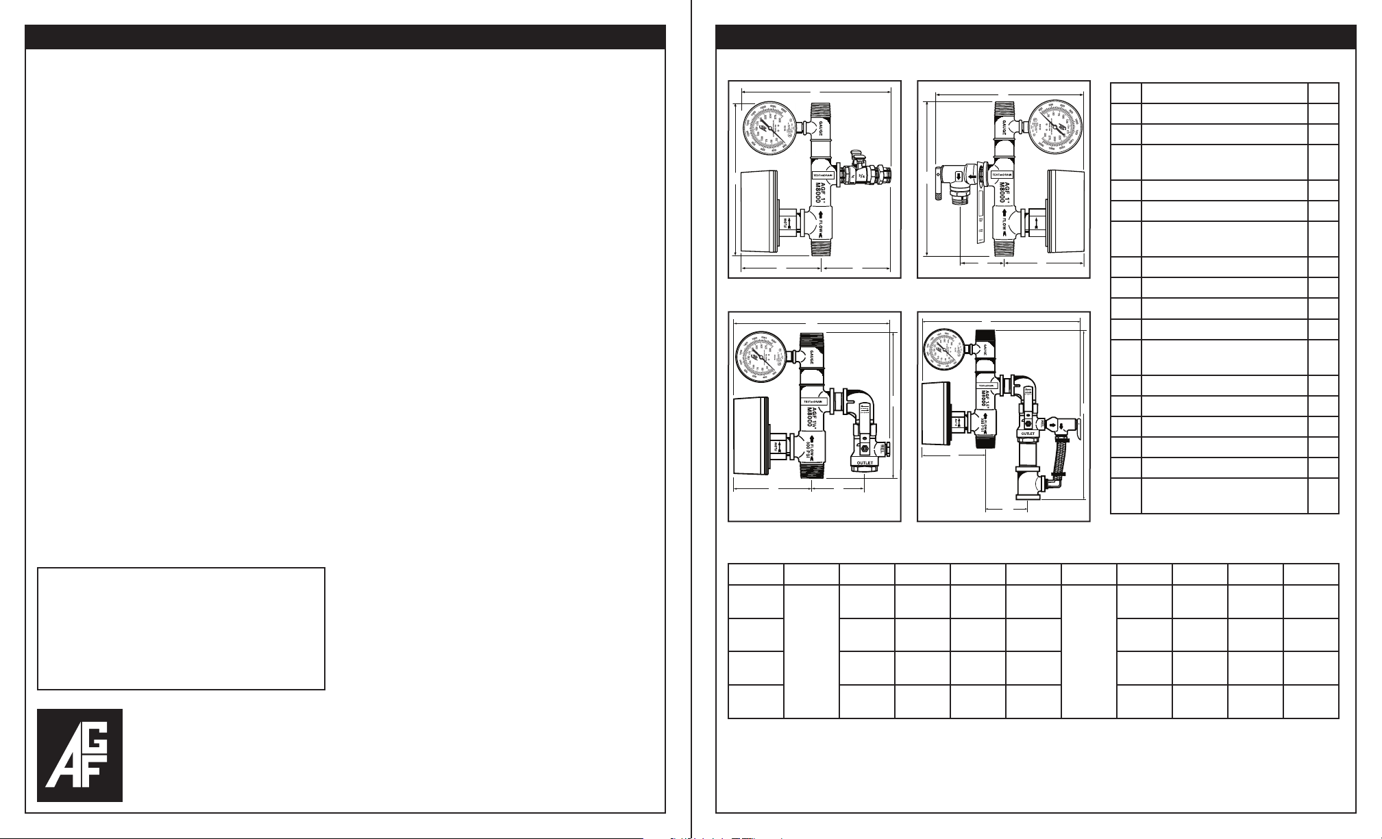
1" mo D e l 8000
1" mo D e l 8011
Co m p o n e n t s
No. Part Qty.
1
Ri s e R PACK® - Bronze Casting 1
2
4
5
1
1¼" – 2" mo D e l 8000
1
4
5
9
1
7
6
2
6
4
5
1¼" – 2" mo D e l 8011
1
4
10
5
3
11
9
10
3
8
14
12
13
16
17
16
15
¾" Male x Female Ball Valve 1
1" M3011BV in s P e C t o R ’stest®
3
Ball Valve
4
M7500 Pressure Gauge 1
5
Water Flow Alarm Switch 1
¾" MNPT x ½" FNPT Hose
6
Adaptor Orifice
7
M7200 ¾" Pressure Relief Valve 1
8
M7000 ½" Pressure Relief Valve 1
9
1" Brass Nipple 1
10
1" Brass Street Elbow 1
½" Brass System Access Port
11
Plug
12
1" Relief Valve Bypass Nipple 1
13
1" Relief Valve Bypass Tee 1
14
½" NPT X-Barb Straight Fitting 1
15
½" NPT X-Barb Elbow Fitting 1
16
Clamps 2
Nylobraid Relief Valve Drain
17
Tubing
Di m e n s i o n s
SIZE Model A B C D Model A B C D
1"
11⁄4"
1½"
2"
101⁄2"
(267 mm)
11"
(279 mm)
12"
(305 mm)
Model 8000
12"
(305 mm)
* Additional space may be necessary to allow for hard drain fitting if required.
** Valve handle clearance required — add 2".
*** Lift handle clearance required — add 31⁄8".
121⁄4"
(311 mm)
43⁄4" *
(121 mm)
121⁄4" **
(311 mm)4"(102 mm)
121⁄2" **
(317 mm)
13"
(329 mm)
41⁄8"
(105 mm)
43⁄8"
(111 mm)
61⁄4"
(159 mm)
61⁄2"
(165 mm)
65⁄8"
(168 mm)
67⁄8"
(174 mm)
101⁄2"
(267 mm)
143⁄4"
(375 mm)
151⁄4"
(387 mm)
Model 8011
151⁄4"
(387 mm)
121⁄4"
(317 mm)
27⁄8" ***
(73 mm)
15"
(381 mm)4"(102 mm)
151⁄4"
(387 mm)
153⁄4"
(399 mm)
41⁄8"
(105 mm)
43⁄8"
(111 mm)
1
1
1
1
61⁄4"
(159 mm)
61⁄2"
(165 mm)
65⁄8"
(168 mm)
67⁄8"
(174 mm)
 Loading...