

Pre-Assembled TESTa n DRAIN® Riser
Bronze:
1¼" 1½" 2"
Sch. 40 Powder Coated:
2½" 3" 4" 6"
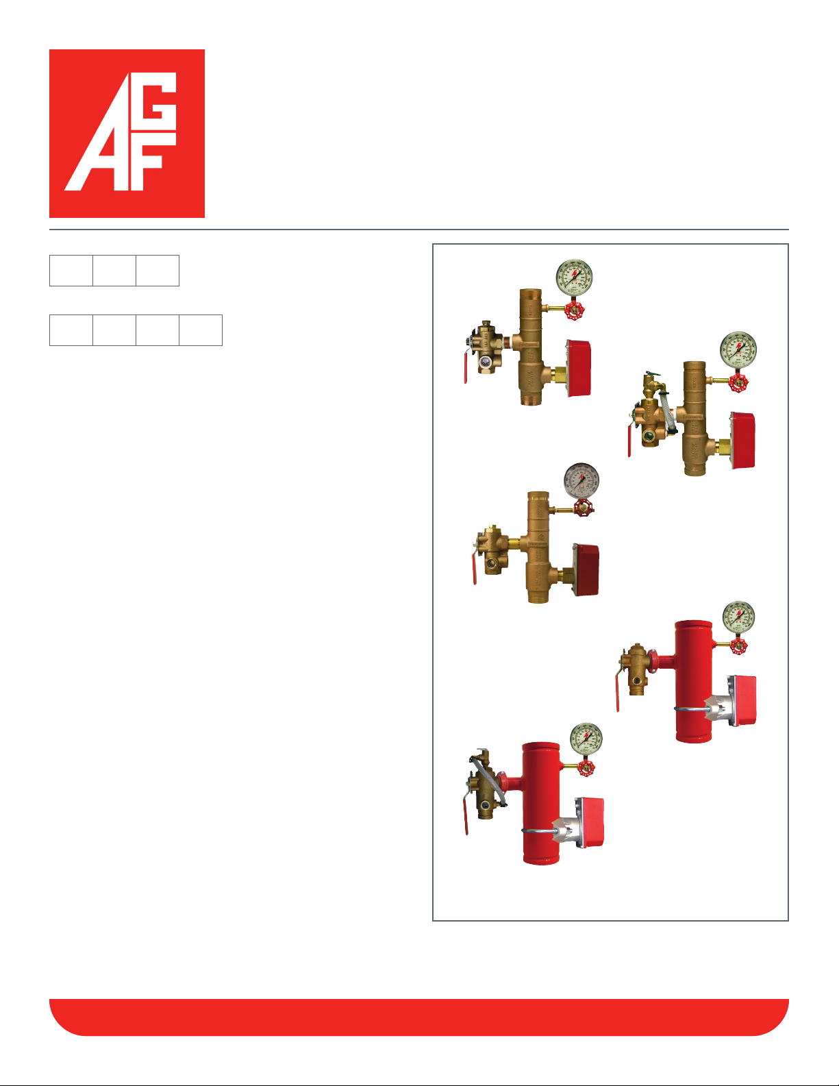
The AGF Commercial Ri s e r PACK™ Model 8000/8011
are compact pre-packaged economical riser assemblies
designed for NFPA 13 wet fire sprinkler systems. Every
model utilizes an appropriate sized UL Listed/FM Approved
patented AGF Model 2500 or 2511 TESTa n DRAIN® valve
designed to comply with NFPA 13 requirements requiring
a sight glass for verification during testing through a
properly sized orifice. All Ri s e r PACKs™ are assembled
with UL Listed/FM Approved AGF Model 7500 Pressure
Gauge (300 PSI), Model 7600 ¼" 3-Way Globe Valve, and
either a 1" NPT or Saddle Mount Water Flow Switch as
required by NFPA 13. The Model 8011 includes UL Listed/
FM Approved AGF Model 7000 Pressure Relief Valve (175
Rated); other ratings are available and may be substituted:
165, 185, 195, 205, 225, or 250.
1¼", 1½", and 2" Models are cast bronze with male •
threaded, grooved, or threaded x grooved ends.
2½", 3", 4", and 6" models are Schedule 40 steel with •
3mil red powder coated finish and grooved ends
300 PSI rating•
Horizontal or Vertical Installation•
1¼", 1½", and 2" models feature a 1" FNPT M2500 or •
M2511 with available orifice sizes of 3⁄8" to 5⁄8" (ELO)
2½" and 3" models feature a 1¼" FNPT M2500 or •
M2511 with available orifice sizes of 3⁄8" to ¾" (ESFR)
4" and 6" models feature a 2" grooved M2500 or M2511 •
with available orifice sizes of 3⁄8" to K-25
The Model 2500/2511 TESTa n DRAIN® valve offers a
unique design benefit that allows system access through
the valve for system integrity testing and/or installation
of the optional relief valve trim kit (Model 8011) without
draining the system.
Model 8000/8011
c o m m e r c i a l
™
ri s e r PacK
Model 8000
Bronze, Threaded
Model 8011
Bronze, Grooved
Model 8000
Bronze, Thread x Groove
Model 8000
Sch. 40 Powdercoated
Model 8011
Sch. 40 Powdercoated
NOTE: It is important to note that the pressure rating of the relief valve indicates an operating range of pressure for both opening and closing of the valve. Standard relief
valves are required to OPEN in a range of pressure between 90% and 105% of their rating. The valves are required to CLOSE at a pressure above 80% of that rating.
The relief valve should be installed where it is easily accessible for maintenance. Care should be taken that the relief valve CANNOT be isolated from the system when the
system is operational. A relief valve should NEVER have a shutoff valve or a plug downstream of its outlet.
Reliability, Versatility, Code Compatibility
Reliability, Versatility, Code Compatibility
SS-M8000M8011-COM · 02/14 TESTan DRAIN® and Re m o t e TEST® are registered trademarks of AGF Manufacturing Inc.
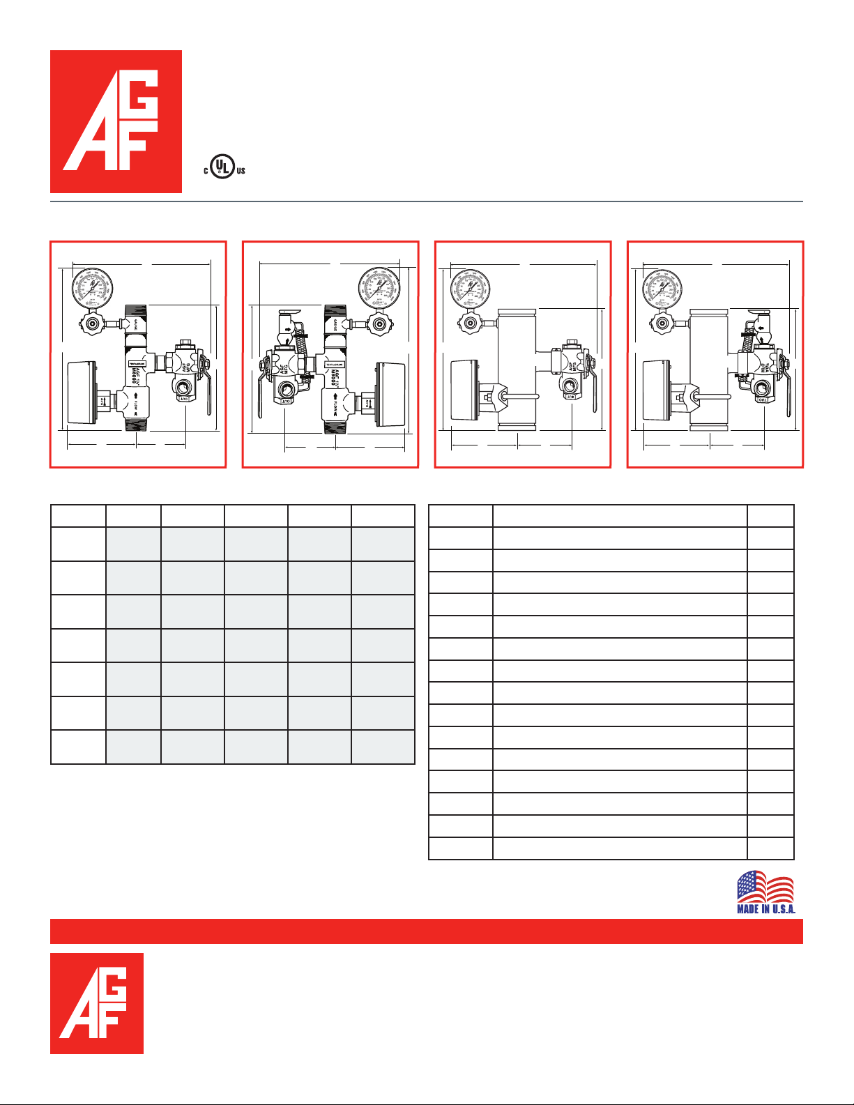
Model 8000/8011
A
B
C
D
E
A
B
C
D
E
B
A
E
C
D
B
A
E
C
D
c o m m e r c i a l
ri s e r PacK
™
1¼"-2" Model 8000 1¼"-2" Model 8011
6
11
10
9 9 9 9
7
14 14 15 15
1
3
8
5 5
12
13
4
8
11
6 6 6
1
12
7
Dimensions
SIZE A B C D E
11⁄4"
1½"
2"
2½"
3"
4" *
6" *
141⁄2"
(369 mm)
151⁄2"
(394 mm)
151⁄2"
(394 mm)
171⁄8"
(435 mm)
171⁄8"
(435 mm)
171⁄8"
(435 mm)
171⁄8"
(435 mm)
*4" and 6" Ri s e r PACKs™ feature a 2" groove x groove M2500/2511
TESTa n DRAIN® valve.
Dimensions have been rounded to the nearest ¼", except "E".
Confirm that enough space is left between the Ri s e r PACK™ and
any obstructions to move handle of M2500/2511 TESTa n DRAIN®
14"
(356 mm)
141⁄4"
(362 mm)
143⁄4"
(374 mm)
141⁄4"
(362 mm)
15"
(381 mm)
19"
(483 mm)
211⁄8"
(537 mm)
43⁄4"
(120 mm)
43⁄4"
(120 mm)
61⁄2"
(165 mm)
63⁄4"
(171 mm)
5"
(127 mm)7"(178 mm)
55⁄8"
(143 mm)6"(152 mm)
57⁄8"
(149 mm)
8"
(203 mm)
91⁄8"
(232 mm)
63⁄8"
(162 mm)
67⁄8"
(175 mm)
77⁄8"
(200 mm)
11"
(279 mm)
12"
(305 mm)
12"
(305 mm)
14"
(356 mm)
14"
(356 mm)
14"
(356 mm)
14"
(356 mm)
2½"-6" Model 8000
10
10 10
7
Components
Item No. Part Qty.
1
2
3
4
5
6
7
8
9
10
11
12
13
14
15
2 2
3
RiserPACK - Bronze Casting 1
RiserPACK - Sch. 40 Powdercoated 1
M2500 TESTa n DRaIn Valve 1
M2511 TESTa n DRaIn Valve 1
M7000 Pressure Relief Valve 1
M7500 Pressure Gauge 1
M7600 ¼" 3-Way Globe Valve 1
Brass Nipple 1
Brass Nipple 1
¼" Brass Plug 1
½" Brass NPT x Barb 90˚ Elbow 2
Clamps 2
Nylobraid Drain Tubing 1
NPT Water Flow Switch 1
Saddle Mount Water Flow Switch 1
valve into the "TEST" position and into the "DRAIN" position.
2½"-6" Model 8011
11
7
12
13
4
12
11
USA Patent and Other Patents Pending
100 Quaker Lane, Malvern, PA 19355
Phone: 610-240-4900
Fax: 610-240-4906
www.testandrain.com
AGF Manufacturing Inc.
Job Name:__________________________________
Architect: ___________________________________
Engineer: ___________________________________
Contractor: _________________________________
 Loading...