


AGF Manufacturing Inc.
Model 5100A, 5200A,
and 5100ALBV
Owner’s Manual
INST-COLLECTan DRAIN_V001.9
Model 5100ALBV
Model 5100A
Model 5200A
Model 5100A, 5200A and 5100ALBV Owner’s Manual
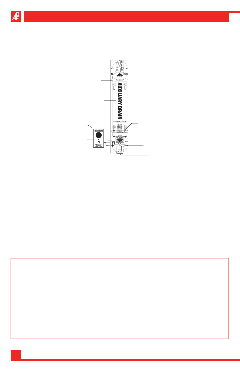
COLLECTa n DRAIN™ Anti-Trip Auxiliary Drains for
Dry Pipe and Pre-Action Fire Sprinkler Systems
Supply Side (Upper)
Ball Valve
Condensate Nipple
Anti-Trip Plate
Water Detection
Alarm
Test Button
(On Back Side)
Model 5100A
Anti-Tamper Lock
Drain Side (Lower)
Ball Valve
Plug
Table of Contents
Installation Instructions
Model 5100A/5200A ............................................................................................. 3
Model 5100ALBV ..............................................................................................3-4
Operation Instructions
Model 5100A/5200A ............................................................................................. 4
Model 5100ALBV ..............................................................................................5-7
WARNING: The COLLECTa n DRaIn™ Anti-Trip Plate is designed to make
sure that the auxiliary drain is operated in the proper manner and correct
sequence as per NPFA guidelines to avoid accidental tripping, improper
maintenance, and acts of vandalism. The M5100ALBV Water Detection
Alarm detects the presence of water in the COLLECTa n DRaIn™ and alerts
personnel when maintenance is needed. COLLECTa n DRaIn™ Model
5100A and 5200A are not designed to prevent freezing or automatically
drain condensation from the system. Failure to drain condensation
from system may result in catastrophic system failure due to
freezing. System must be maintained per NFPA 25 4.6, 4.6A and 4.1.
2

Model 5100A/5200A Installation Instructions
Retro-fitting into an Existing System
Isolate branch line or zone where the 1. COLLECTa n DRaIn™ is to be installed.
Relieve air pressure from the branch line.2.
Remove existing auxiliary drain/condensation collection assembly.3.
Install the 4. COLLECTa n DRaIn™ by attaching the supply valve (upper) to the
sprinkler system pipe in accordance with NFPA 13 (2013 edition) 8.16.2.5 and
8.16.2.5.3 with regards to low-point drains (auxiliary drains).
Confirm that the supply valve (upper) is in the open position and ready to collect 5.
condensation, the drain valve (lower) is closed, and the plug is tight.
Return system back to normal operating conditions.6.
Installation into a New System
Install the 1. COLLECTa n DRaIn™ by attaching the supply valve (upper) to the
sprinkler system pipe in accordance with NFPA 13 (2013 edition) 8.16.2.5 and
8.16.2.5.3 with regards to low-point drains (auxiliary drains).
Confirm that the supply valve (upper) is in the open position and ready to collect 2.
condensation, the drain valve (lower) is closed, and the plug is tight.
Activate system for normal operating conditions.3.
Note: The presence of even a small amount of water in the COLLECTa n DRaIn™
Model 5100A will activate the Model 5100ALBV Alarm’s visual and audible
alerts signaling the need for attention. The COLLECTa n DRaIn™ must be drained
completely to silence the alarm. Please call 610-240-4900 for instructions on how
to locally silence the audible alert if directly wired to a Fire Control Panel or BMS.
Model 5100A/5200A Operating Instructions
To Collect Condensate per NFPA 25 (2011 edition) A.13.4.4.3.2, 13.4.4.3.2*
Close the drain valve (lower) by making sure the valve handle is perpendicular 1.
to the collection assembly.
Apply Teflon2.
the bottom of the drain valve.
Slide the Anti-Trip Plate to its lowest position.3.
Open the supply valve (upper) by making sure the valve handle is in line with 4.
the collection assembly.
If equipped, install the anti-tamper lock.5.
AGF Manufacturing Inc. • Phone: 610-240-4900 • Fax: 610-240-4906 • www.agfmanufacturing.com
®
tape to the plug and make sure the plug is tightly threaded into
3

Model 5100A, 5200A and 5100ALBV Owner’s Manual
To Drain Condensate per NFPA 25 (2011 edition) A.13.4.4.3.2, 13.4.4.3.2*
Close the supply valve (upper) and remove plug.1.
Slide the Anti-Trip Plate to its highest position and open the drain valve (lower) 2.
to drain the accumulated water.
Once the water has been drained, close the drain valve (lower) and slide the 3.
Anti-Trip Plate to its lowest position.
Open the supply valve (upper) and allow time for any remaining water in the 4.
system to accumulate. Repeat steps 1-3 until all of the water has been drained
from the system.
Once all water has been drained apply new Teflon5.
®
tape to the plug and make
sure it is tightly threaded into the bottom of the drain valve.
Close the drain valve (lower) and slide the Anti-Trip plate down into its lowest 6.
possible position.
Open the supply valve (upper).7.
If equipped, install the anti-tamper lock.8.
Model 5100ALBV Installation Instructions
The alarm module operates on the principle of conductivity. The alarm contains a
probe that is attached to the piping system. When condensate collects in the piping
and reaches the probe, the electrical circuit is completed and the unit sounds an
audible alarm, flashes a visual red LED, and changes the state of the output relay.
The module will reset itself when the condensate is completely drained.
Retro-fitting onto an Existing Auxiliary Drain
Isolate the auxiliary drain that the 1. COLLECTa n DRaIn™ Model 5100ALBV is to
be installed on.
Remove the plug and open the drain valve (lower) to empty the condensate 2.
from the auxiliary drain and relieve the air pressure.
Remove the existing drain valve (lower) from the auxiliary drain.3.
Apply PTFE tape or appropriate sealant to the Model 5100ALBV.4.
Install the Model 5100ALBV by threading the valve into the appropriate fitting.5.
Confirm that the drain valve (lower) is closed and the plug is tight. Open the 6.
supply valve (upper) and the auxiliary drain is ready to collect condensate.
Return system back to normal operating conditions.7.
See Page 5-7 for Wiring Instructions.8.
4
Model 5100ALBV Operating Instructions
+V
-V
COM
T
EMPERATURE
JUMPER
VOL T AGE
JUMPER
N.O.
N.C.
Power is supplied to the Model 5100ALBV by a 9V Battery (default) or by installing
a 12-24VDC external hard wire (See Page 6). The 5100ALBV can draw up to
100mA during operation. Ensure the power supply is sized appropriately for
this and any other loads on the same circuit.
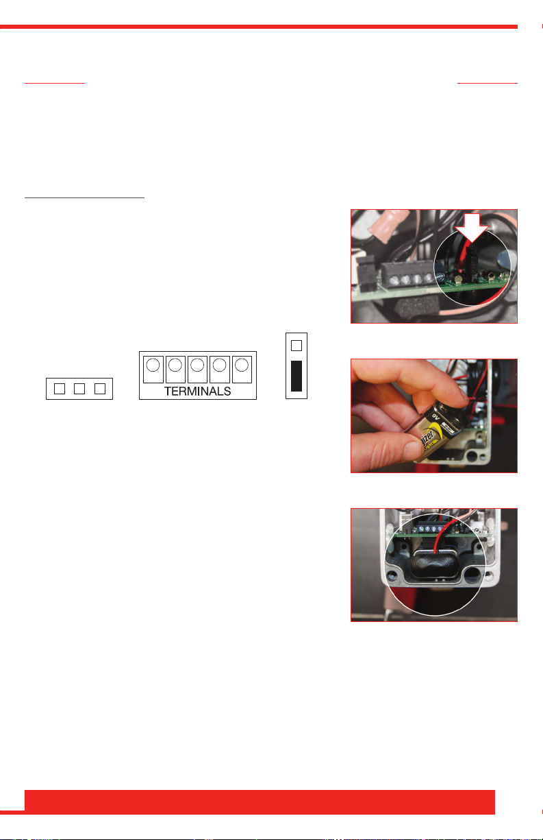
Battery Operation:
Remove four screws on the alarm box and take 1.
off the cover.
For battery operation, check to make sure the 2.
Voltage Jumper is on the front two pins as
shown in Image 1 (Fig. A).
VOLTAGE
JUMPER
(Fig. A)
Install a 9V battery as shown in Image 2.3.
Note: When the battery begins to run low the
alarm will chirp and flash a yellow LED.
Place 9V battery under the circuit board as 4.
shown in Image 3.
Install cover with the four screws.5.
Image 1
Image 2
AGF Manufacturing Inc. • Phone: 610-240-4900 • Fax: 610-240-4906 • www.agfmanufacturing.com
Image 3
5

Model 5100A, 5200A and 5100ALBV Owner’s Manual
+V
-V
COM
T
EMPERATURE
JUMPER
VOL T AGE
JUMPER
N.O.
N.C.
External Hardwire Operation:
Remove four screws on the alarm box and take 1.
off the cover.
For external power operation, place the 2. Voltage
Jumper on the rear two pins as shown in Image
4 (Fig. B).
VOLTAGE
JUMPER
(Fig. B)
While supporting the bottom of the alarm 3.
enclosure, remove the knockout using a slotted
screwdriver and a hammer (Place a clean rag
underneath the knockout to prevent debris from
falling onto the circuit board).
Install ½”, watertight conduit fitting or cord grip 4.
into the knockout opening and run the external
power source into the alarm housing as shown
in Image 5.
Connect external power source to V+ and V- 5.
terminals ash shown in Image 6 (Fig. B). Ensure
DC is from a clean power supply and not fullwave rectified without a capacitor.
Install cover with the four screws.6.
Image 4
Image 5
Image 6
Temperature Sensing Function
When the Temperature Sensing Function is enabled and water is present in the
auxiliary drain the Model 5100ALBV will not activate the audible and visual alerts
if the ambient temperature is above 45° F. When water is present and the ambient
temperature falls below 45° F, the Model 5100ALBV will activate the audible and
visual alerts. The Temperature Sensing Function helps extend battery life and
eliminates unwanted alarm conditions when the threat of freezing is not present.
By default the Temperature Sensing Function is enabled when shipped,
meaning the alarm senses water only when the temperature is under 45° F.
See page 7 to disengage Temperature Sensing Function.
6

+V
-V
COM
T
EMPERATURE
JUMPER
VOL T AGE
JUMPER
N.O.
N.C.
+V
-V
COM
T
EMPERATURE
JUMPER
VOL T AGE
JUMPER
N.O.
N.C.
To Disengage the Temperature Sensing Function:
Remove four screws on the alarm box and take 1.
off the cover.
Remove 2. Temperature Jumper from left/center
pins and reinstall on right/center pins as shown
in Image 7 (Fig. C).
TEMPERATURE
JUMPER
Install cover with the four screws.3.
(Fig. C)
NOTE:
Left/Center pins covered (Temp -): Alarm •
functions at < 45º F (engaged)
Right/Center pins covered (Temp +): Alarm •
functions at all times (disengaged)
Image 7
Note: If the Temperature Jumper only utilizes two pins call for instructions on
how to engage/disengage the Temperature Sensing Function.
Remote Notification Function
The Model 5100ALBV Water Detection Alarm also features a Remote Notification
Function. This function allows you to connect the unit directly to the Fire Control
Panel or BSM so when water is detected in the auxiliary drain you will be notified
remotely.
Remote Operation Setup:
Remove four screws on the alarm box and take 1.
off the cover.
Connect wiring to the 2. Common Terminal and
either the N.O. or N.C. terminal as shown in
Image 8 (Fig. D). Contact is rated for 2.0A @
30VDC.
COM
N.O.
N.C.
Image 8
TERMINALS
(Fig. D)
Install cover with the four screws.3.
Note: Please call for instructions on how to locally silence the audible alert if
directly wired to a Fire Control Panel or BMS.
Thank You For Using AGF Products!
AGF Manufacturing Inc. • Phone: 610-240-4900 • Fax: 610-240-4906 • www.agfmanufacturing.com
7

Auxiliary Drain Freeze Protection
The Model 5400A goes beyond the prevention features of the Model 5100A
and 5200A by providing a temperature controlled environment to deter
system failures due to freezing condensation. The heated and insulated
cabinet contains an auxiliary drain with a float switch to monitor condensation
levels. When condensation reaches a level where maintenance is needed
the float switch activates an audible alarm and an LED warning light. The
Model 5400A also features Fire Control Panel notification capabilities. Visit
www.collectandrain.com for more information.
AGF Manufacturing Inc.
100 Quaker Lane • Malvern, PA 19355
Phone: 610-240-4900
Fax: 610-240-4906
www.agfmanufacturing.com
 Loading...