

AGF Manufacturing 3011 Installation Manual
INSTALLATION INSTRUCTIONS
MODEL 3011 PATENTED AND OTHER PATENTS PENDING 1" SIZE
INSPECTORS TEST
THE 3011 SUBASSEMBLY, CONSISTING OF THE MODEL 3011 INSPECTORS TEST VALVE (WITH THE
RELIEF VALVE PORT PLUGGED), THE CONNECTION NIPPLE AND THE BYPASS TEE (WITH THE BYPASS
BRANCH PLUGGED) SHOULD BE INSTALLED AS THE INSPECTORS TEST VALVE AT THE END OF A
GRIDDED SYSTEM OR WHEN A REGULATING VALVE IS USED IN A SINGLE STORY BUILDING.
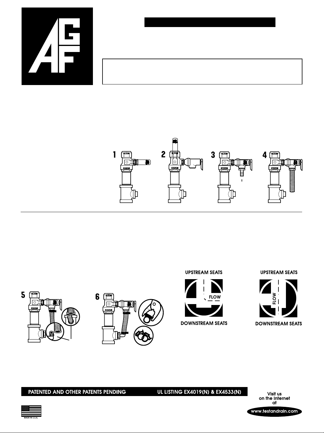
1. Turn the Model 3011 valve handle
to the ”CLOSED” position for the
hydrostatic test of the system
(see drawing 1).
2. Hydrostatically test the system.
3. To install the relief valve and
drain assembly follow this
procedure:
A. Shut off the system at the
supply valve.
B. Turn the Model 3011 valve
handle to the "test" position to
drop the system pressure (see
drawing 2).
C. After the system pressure is
dropped, remove the relief
valve port plug while the
system is draining (see
drawing 2).
H. Remove the plastic plug from the
bypass tee branch and install the
male X-barb elbow into the bypass
tee branch, rolling the barb elbow
into the flexible tubing on the last
turn of the elbow (see drawing 5).
I. Full assembly requires tightening
two pipe clamps on hose barb
fittings (see drawing 6). Clamps
provided.
D. Install the Model 7000 relief
valve in the relief valve port
with the relief valve outlet
pointed toward the bypass tee
branch inlet (see drawing 2).
E. Return the Model 3011 valve
handle to the “closed”
position (see drawing 3).
J. Repressurize the system.
Figure "A" shows the assembly in
the "OFF" position. There is no flow
THROUGH the valve. There is flow
from the inlet into the Relief Valve
providing pressure relief to the
system as required under
Paragraph 5-1.3 of NFPA13.
F. Install the straight male X-
barb adaptor into the outlet
of the Model 7000 relief valve.
G. Install the flexible tubing on
the male X-barb adaptor
(see drawing 4).
X-BARB
The valve in the "TEST" position as
shown in Figure "B" allows flow from
the inlet through the orifice in the
ball providing a testing facility as
required in Paragraph 3-4.1.1 of the
NFPA specifications.
side view
front view
X-BARB
Valve seated in
"OFF" position.
Flow from inlet of
valve to side outlet
into relief valve.
AGF MANUFACTURING INC.
100 Quaker Lane • Malvern, PA 19355
Telephone: (610) 240-4900 • Fax: (610) 240-4906
Figure A
Figure B
Valve seated in
""TEST" position.
Flow from inlet of
to straight
valve
outlet of valve
through orifice
in ball.
 Loading...