

Page 1
AGF Manufacturing Inc.
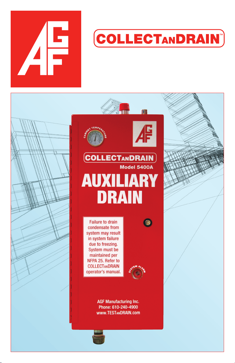
Model 5400A
Owner’s Manual
INST-5400A · 1/13
1
Page 2

AGF Manufacturing Inc.
TABLE OF CONTENTS
Installation Instructions ...................................................................4
Unpacking .........................................................................................4
Sprinkler System Preparation ...........................................................4
Mounting ...........................................................................................4
Wiring ................................................................................................5
Verify Correct Operation ...................................................................6
Operating Instructions ................................................................. 6-8
Maintenance Instructions ................................................................9
Verify Alarm Operation ......................................................................9
Heater Operation ..............................................................................9
Changing Thermostat Setting .........................................................10
Notes ..............................................................................................10
Maintenance Log ............................................................................11
AGF Manufacturing Inc.
100 Quaker Lane • Malvern, PA 19355
Phone: 610-240-4900
Fax: 610-240-4906
www.testandrain.com
Page 3
Model 5400A COLLECTa n DRAIN™ Owner’s Manual
Model 5400A COLLECTa n DRAIN
™
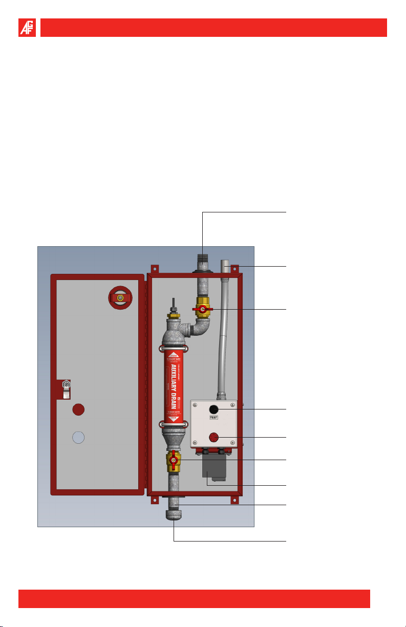
The Model 5400A COLLECTa n DRAIN™ is a heated and insulated condensate collector and auxiliary drain with water level alarm for dry pipe sprinkler systems.
The M5400A is designed for installation in climates where freezing or below freezing temperatures are present and result in the failure of typical collectors. The
M5400A maintains a comfortable temperature above freezing while minimizing
power consumption.
System Supply Pipe
Electrical Connection
System Supply Valve
“TEST” Button
Alarm Light
System Drain Valve
Heater
System Drain Pipe
Drain Pipe Cap
AGF Manufacturing Inc. • Phone: 610-240-4900 • Fax: 610-240-4906 • www.testandrain.com
3
Page 4
Model 5400A COLLECTa n DRAIN™ Owner’s Manual
INSTALLATION INSTRUCTIONS
Unpacking:
Unpack the M5400A COLLECT1. a n DRAIN™ unit and carefully inspect for any
damages from shipping.
Verify box contents:2.
M5400A COLLECT• a n DRAIN™ unit
Four (4) Rubber Mounting Washers•
Two (2) Door Keys•
Electrical Wiring Schematic•
M5400A System Drawing•
Sprinkler System Preparation:
If installing in a new system, proceed to Mounting Instructions below, otherwise
continue with Preparation Instructions.
If adding additional installations, see NFPA 13 Chapters 24 and 26, and NFPA 25
Chapter 14.
Isolate the zone where the COLLECT1. a n DRAIN™ will be installed.
Relieve air pressure from the branch line.2.
Remove the existing auxiliary drain.3.
Mounting:
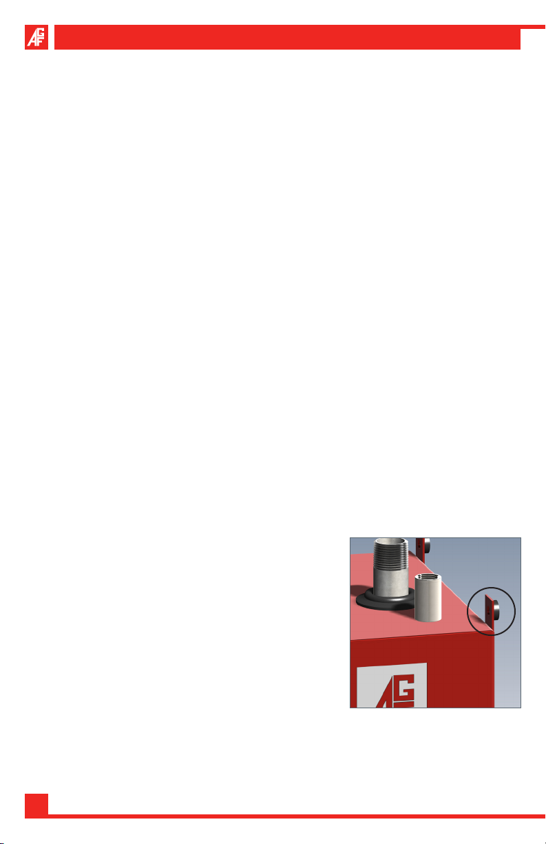
Use the four mounting tabs (3/8” holes x 4) to install the M5400A to a wall or other
secure structure.
Place the rubber washers behind the mounting 1.
tabs to hold the M5400A off of the wall. Select
fasteners suitable for attachment and capable
of supporting the 50 lb. weight of the M5400A.
Connect to the 1” NPT Supply Pipe in accor-2.
dance with NFPA 13 (8.16.2.5 and 8.16.2.5.3) in
regards to low-point drain installations.
Confirm that the Supply Valve (upper valve) is in 3.
the open position (vertical) and ready to collect
condensation, the Drain Valve (lower valve) is
in the closed position (horizontal), and the pipe
cap is tight.
4
Page 5
Wiring:
The M5400A requires 120VAC power source to function.
Run conduit to the ½” connection on the top of the unit.1.
Open the door using the supplied keys.2.
Loosen the four screws on the front of the M5400A Alarm Panel Box and 3.
carefully remove the door.
Run appropriately sized power wires into the Alarm Panel 4.
(Refer to the electrical schematic as necessary).
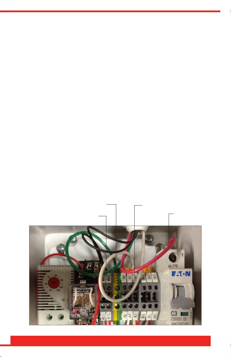
Connect the 120VAC Hot Wire to the circuit breaker.5.
Connect the 120VAC Neutral Wire to one of the three neutral terminals.6.
Connect the ground wire to the green ground terminal.7.
The M5400A can be connected to a Remote Panel. This is accomplished
through a set of N.O. (close on alarm) auxiliary contacts.
Run two additional wires into the M5400A Alarm Panel.1.
Connect one wire to the AC1 (auxiliary contact) Terminal.2.
Connect the other wire to the AC2 (auxiliary contact) Terminal.3.
Connect these wires to the appropriate place in the Remote Panel.4.
Ground Wire
Auxiliary Contact Wires
AGF Manufacturing Inc. • Phone: 610-240-4900 • Fax: 610-240-4906 • www.testandrain.com
Neutral Wire
Hot Wire
5
Page 6
Model 5400A COLLECTa n DRAIN™ Owner’s Manual
Verify Correct Operation:
Apply power to the M5400A and verify that correct voltage is present.1.
Turn on the circuit breaker inside of the M5400A alarm panel.2.
Push and Hold the “TEST” button on the front of the alarm panel for five 3.
seconds to verify that the alarm horn sounds and the alarm light pulses.
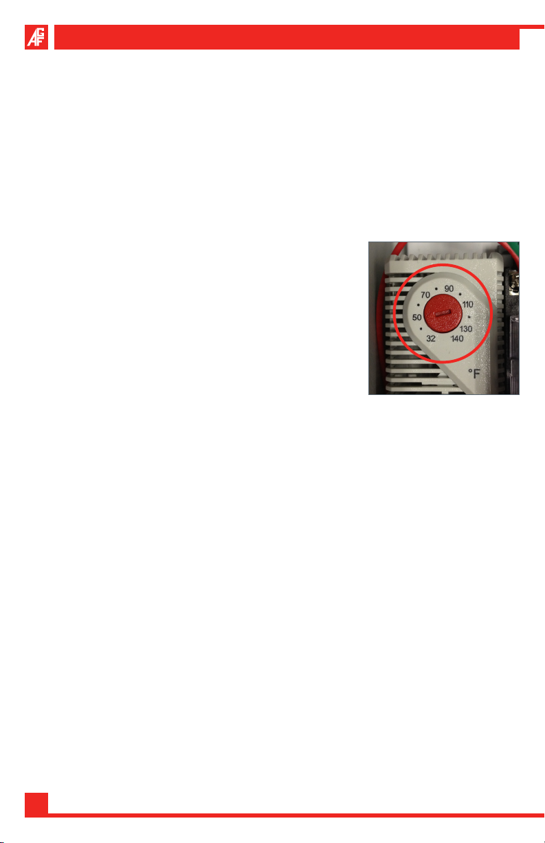
Turn the red Thermostat Set-Point Dial clockwise until the heater turns on.4.
Reset the red Thermostat Set-Point Dial to the factory default of 50º F.5.
NOTE: It is the owner’s responsibility to set the thermostat based upon the climate conditions of the installed
location. The default setting of 50º F is adequate for
outside temperatures down to 0º F. If operating below
this temperature, the set-point should be increased.
Consult AGF for set-point guidelines.
Install the M5400A Alarm Panel Cover and tighten 6.
the four screws securely.
Close and lock the door using the supplied keys.7.
NOTE: If installation was to an existing system, return the system back to normal
operating conditions. If installation was to a new system, activate system for normal operating conditions.
OPERATING INSTRUCTIONS
The M5400A is equipped with a 150W heater controlled by a user-set thermostat.
The factory default setting of 50º F is suitable for conditions down to 0º F. Consult
with AGF for recommended settings if operating the M5400A in areas below 0º F.
The thermostat controls the heater operation to within approximately ± 10º F of
the set-point (i.e. Set-Point=50º F: ON @ 40º F—OFF @ 60º F).
NOTE: AGF does not recommend setting the thermostat below 50º F.
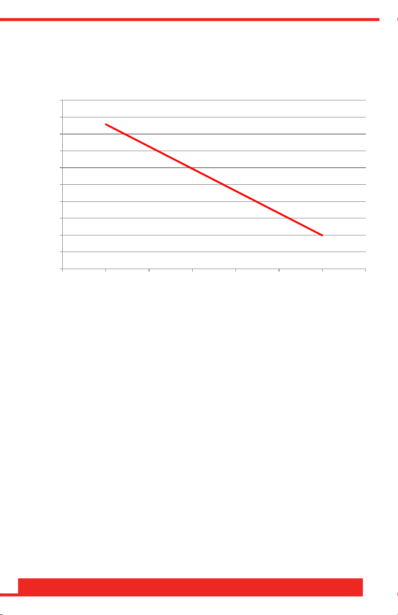
Power Consumption of the M5400A is based on a number of factors including
ambient temperature, humidity, installation location and exposure to sunlight. The
following graph shows an estimation of the daily energy consumption verses ambient temperature when the set-point is 50º F.
6
Page 7
The M5400A features a thermometer on the cabinet for measuring the ambient
0.00
0.20
0.40
0.60
0.80
1.00
1.20
1.40
1.60
1.80
2.00
-20 -10 0 10 20 30 40 50
Power (kWh/day)
Average Ambient Temperature (°F)
Est. Daily Power Consumption
temperature inside the unit. This thermometer is for checking the operating status
of the heater.
The M5400A also features a Float-Style Level Switch for monitoring the collected
condensate. This switch is tied back to the integrated NEMA 4 Alarm Panel. When
enough condensate has accumulated, the Level Switch is activated triggering the
alarm horn to sound and pulse the red light mounted on the M5400A alarm panel.
The alarm horn and light indicates that the M5400A needs to be emptied. An
auxiliary contact is also triggered and is capable of being wired back to a central
control panel for remote indication. The Level Alarm is automatically reset when
the water level is drained below the switch.
The M5400A is equipped with a “TEST” button to confirm that the water alarm
panel is functioning properly. When pressed, the Test Button causes the local
alarm horn and light as well as the remote indication to be triggered.
AGF Manufacturing Inc. • Phone: 610-240-4900 • Fax: 610-240-4906 • www.testandrain.com
7
Page 8
Model 5400A COLLECTa n DRAIN™ Owner’s Manual
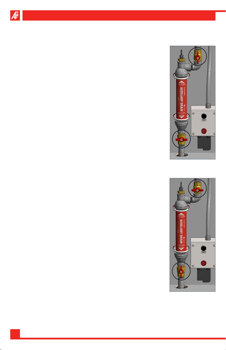
To Collect Condensate per NFPA 25 A.12.4.3.3.3:
CAUTION: Valves may be hot. Use care when operating.
Open the cabinet door using the supplied keys.1.
Close the Drain Valve (lower valve).2.
Install the 1” Pipe Cap onto the drain pipe at the bottom 3.
of the cabinet.
Open the Supply Valve (upper valve).4.
Close and lock cabinet door using the supplied keys.5.
To Drain Condensate per NFPA 25 A.12.4.3.3.3:
CAUTION: Valves may be hot. Use care when operating.
Open the cabinet door using the supplied keys.1.
Close the Supply Valve (upper valve).2.
Remove the 1” Pipe Cap from the drain pipe at the 3.
bottom of the cabinet.
Open the Drain Valve (lower valve) and drain the 4.
accumulated water.
Once the water has been drained, close the Drain Valve 5.
(lower valve).
Open the Supply Valve (upper valve) and allow time for 6.
any additional water to accumulate.
Repeat the process until all of the accumulated water 7.
has been drained.
Once all water has been drained, follow the “COLLECT” 8.
procedure above.
COLLECT
DRAIN
8
Page 9
MAINTENANCE INSTRUCTIONS
Maintenance is the cornerstone to keeping any system operating correctly and
efficiently. It is the building owner’s responsibility to ensure that the M5400A has
been drained of condensation and that the heater and alarm are working properly.
Failure to drain condensation from the system, or conduct regularly scheduled
testing and maintenance could result in system failure due to freezing. System
must be maintained per NFPA 25 4.6, 4.6A, and 4.1.
It is especially important that functional testing of the heater be performed before
the start of the winter season or when temperatures begin to approach freezing
conditions.
Verify alarm operation:
Push and Hold the “TEST” button on the Alarm Panel for five seconds to 1.
verify that the alarm horn sounds and the alarm light pulses.
Verify heater operation:
CAUTION: Always take the necessary precautions when entering the alarm panel
when 120V power is present.
Loosen the four screws on the front of the 1.
M5400A Alarm Panel Box and carefully remove
the door.
Take note of the current thermostat set-point. 2.
Thermostat Set-Point: __________________
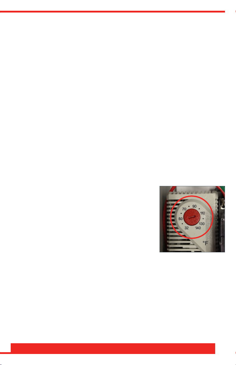
Turn the red Thermostat Set-Point dial clockwise 3.
until the heater turns on.
Reset the red Thermostat Set-Point dial to the 4.
previous setting.
Install the M5400A Alarm Panel Cover and tighten the four screws securely.5.
AGF Manufacturing Inc. • Phone: 610-240-4900 • Fax: 610-240-4906 • www.testandrain.com
9
Page 10
Model 5400A COLLECTa n DRAIN™ Owner’s Manual
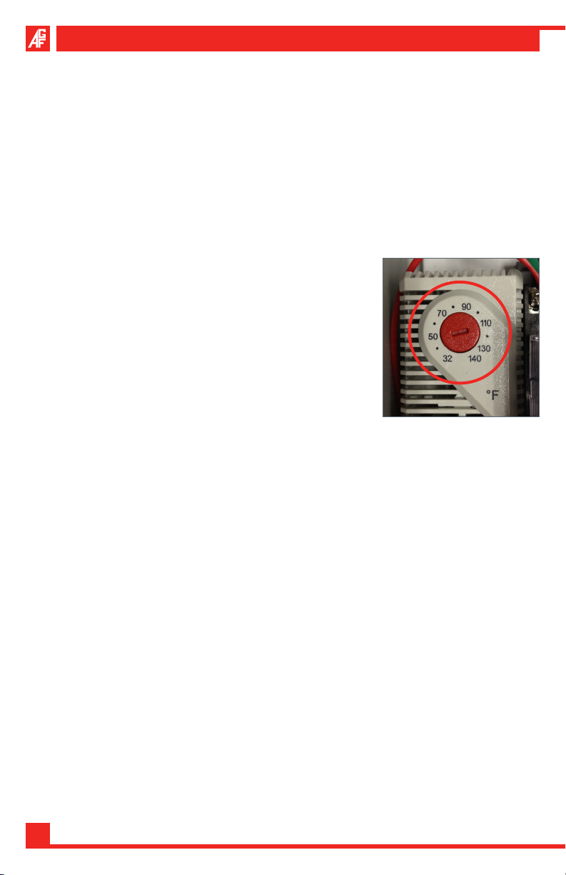
Change Thermostat Setting:
NOTE: It is the owner’s responsibility to set the thermostat based upon the cli-
mate conditions of the installed location. The default setting of 50º F is adequate
for outside temperatures down to 0º F. If operating below this temperature, the
set-point should be increased. Consult AGF for set-point guidelines.
Disconnect electrical power to the M5400A.1.
Loosen the four screws on the front of the M5400A Alarm Panel box and 2.
carefully remove the door.
Turn the red Thermostat Set-Point Dial clockwise 3.
or counterclockwise to the desired setting.
Take note of the new thermostat set-point. 4.
Thermostat Set-Point: __________________
Install the M5400A Alarm Panel Cover and tighten 5.
the four screws securely.
Apply power to the M5400A.6.
Verify that the unit has power by pressing and 7.
holding the “TEST” button.
NOTES
_______________________________________________________________________
_______________________________________________________________________
_______________________________________________________________________
_______________________________________________________________________
_______________________________________________________________________
_______________________________________________________________________
_______________________________________________________________________
_______________________________________________________________________
_______________________________________________________________________
_______________________________________________________________________
10
Page 11

MAINTENANCE LOG
Initials Maintenance Description Date
_________ ________________________________________________ ________
_________ ________________________________________________ ________
_________ ________________________________________________ ________
_________ ________________________________________________ ________
_________ ________________________________________________ ________
_________ ________________________________________________ ________
_________ ________________________________________________ ________
_________ ________________________________________________ ________
_________ ________________________________________________ ________
_________ ________________________________________________ ________
_________ ________________________________________________ ________
_________ ________________________________________________ ________
_________ ________________________________________________ ________
_________ ________________________________________________ ________
_________ ________________________________________________ ________
_________ ________________________________________________ ________
_________ ________________________________________________ ________
_________ ________________________________________________ ________
_________ ________________________________________________ ________
_________ ________________________________________________ ________
_________ ________________________________________________ ________
AGF Manufacturing Inc. • Phone: 610-240-4900 • Fax: 610-240-4906 • www.testandrain.com
11
Page 12

AGF Manufacturing Inc.
100 Quaker Lane • Malvern, PA 19355
Phone: 610-240-4900
Fax: 610-240-4906
www.testandrain.com
 Loading...