

Page 1
查询D2526G17供应商
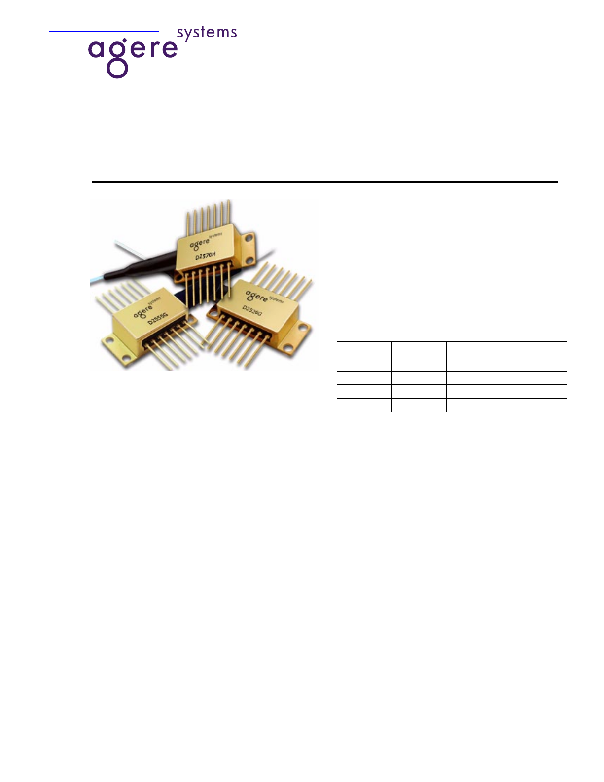
D2570, D2526, D2555 Wa velength-Selected
Direct Modulated Isolated DFB Laser Module
Data Sheet, Rev. 3
July 2001
Applications
■
Three direct-modulated DWDM families available
to meet a number of OC-48/STM-16 applications:
—Extended reach (100 km)
—Very long reach (170 km)
—Metro DWDM
—Digital video
The 1.5 µm D2570, D2526G, and D2555 Laser Modules are
available in a 14-pin, hermetic, butterfly package.
Features
■
ITU wavelengths available from
1528.77 nm —1610.06 nm
■
SONET/SDH compatible up to OC-48/STM-16
■
Temperature tunable for precise wavelength
selection
■
Integrated optical isolator
■
High-performance, multiquantum well (MQW)
distributed-feedback (DFB) laser
■
Industry-standard, 14-pin butterfly package
■
Characterized at 2.488 Gbits/s (NRZ)
■
InGaAs, PIN photodetector back-facet monitor
■
Low threshold current
■
High-reliability, hermetic packaging
■
Excellent long-term wavelength stability can eliminate the need for external wavelength locker
■
Qualified to meet the intent of
gies
* 468
*
Telcordia Technologies
Inc.
is a trademark of Telcordia Technologies,
Telcordia Technolo-
Product Codes
Product
Code
D2570H 10 mW 1800 ps/nm (100 km)
D2526G 2 mW 1800 ps/nm (100 km)
D2555G 2 mW 3000 ps/nm (170 km)
Peak
Power
Dispersion
Performance
Description
The Direct Modulated Isolated DFB Laser Module
contains an internally cooled, InGaAs, MQW, distributed-feedback (DFB) laser designed for 1.5 µm applications. The f ollowing three d irect-modulation D WDM
product families have been established to meet various OC-48/STM-16 system applications:
■
D2526-type: designed to be used in OC-48/
STM-16 (2.488 Gbits/s) for extended reach, dense
WDM applications (1800 ps/nm). The wavelength
of the laser can be temperature-tuned for precise
wavelength selection by adjusting the temperature
of the internal thermoelectric cooler.
■
D2555-type: high-perf ormance device designe d for
very low dispersion; used in fi ber sp ans exceeding
170 km (3000 ps/nm).
■
D2570-type: high-power, direct-modulated laser
eliminates the need for optic al amplifier s in DWDM
many applications.
Page 2
D2570, D2526G, D2555 Wavelength-Selected Data Sheet, Rev. 3
Direct Modulated Isolated DFB Laser Module July 2001
Description
(continued)
Controlled Feedback
The module contains an internal optical isolator that
suppresses optical fee dbac k in l aser-based, fi ber-opt ic
systems. Light reflected back to the laser is attenuated
a minimum of 30 dB.
Controlled Temperature
An integral thermoelectric cooler (TEC) provides stab le
thermal characteristics. The TEC allows for heating
and cooling of the laser chip to mai ntain a te mper ature
of 25 °C for case temperatures from –40 °C to +70 °C .
The laser temperature is monitored by the internal
thermistor, which can be used wi th external circuitry to
control the laser chip temperature.
Controlled Power
An internal, InGaAs, PIN photodiode functions as the
back-f a ce t moni tor. The photodiode monitors emission
from the rear facet of the laser and, when used in conjunction with control circuitry, can control optical power
launched into the fiber. Normally, this configuration is
used in a feedback arr angement to maintain consistent
laser output power.
Standard Package
The laser module is fabricated in a 14-pin, hermetic,
metal/ceramic butterfly package that incorporates a
bias tee, which separates the dc-bias path from the RF
input. The RF input has a nominal 25 Ω impedance.
The laser module is equipped with
SMF-28
The fiber has a 900 µm tight buffer jacket. Var ious connectors and pigtail lengths are available.
*
type fiber .
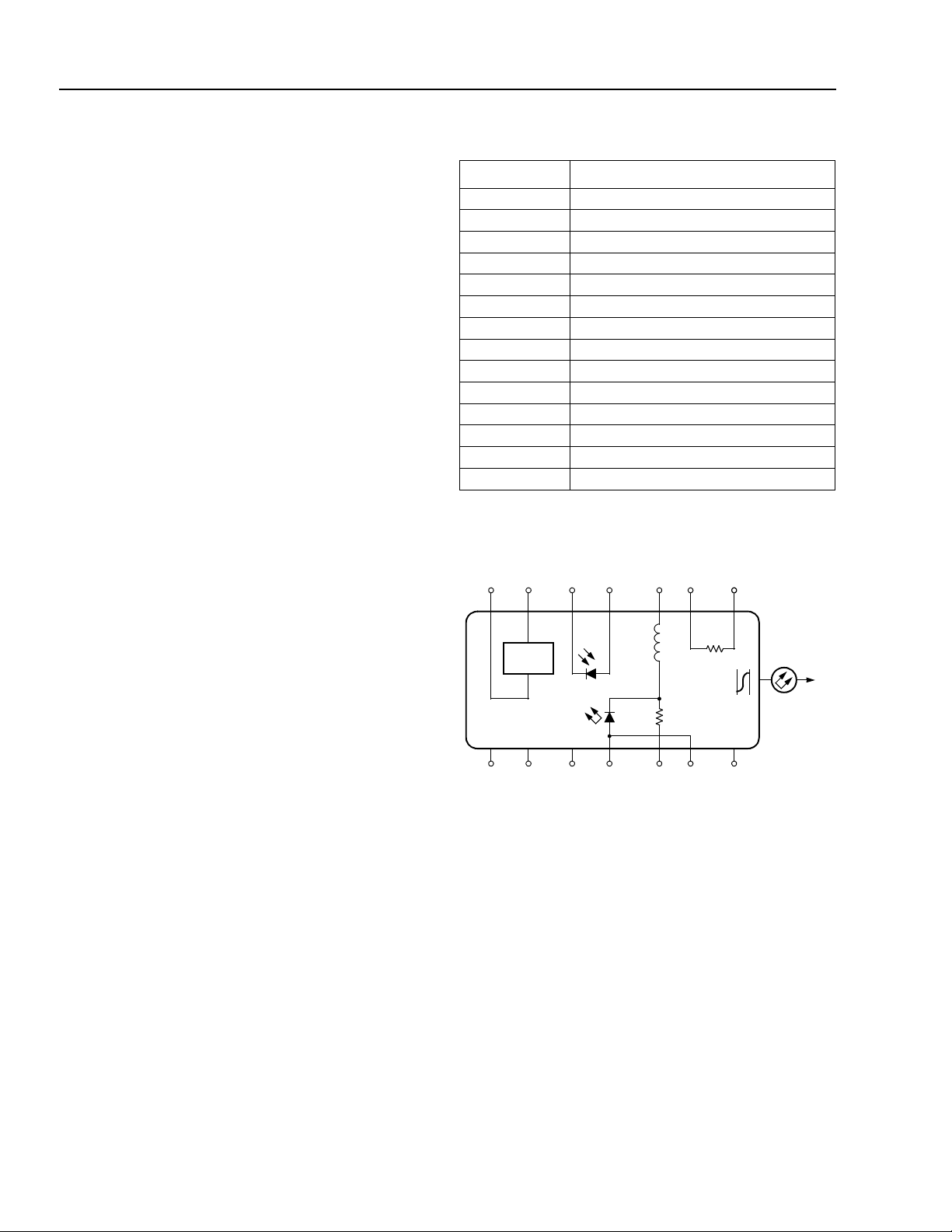
Pin Information
Pin Name
1 Thermistor
2 Thermistor
3 Laser dc Bias (Cathode) (–)
4 Back-facet Monitor Anode (–)
5 Back-facet Monitor Cathode (+)
6 Thermoelectric Cooler (+)*
7 Thermoelectric Cooler (–)
8 Case Ground
9 Case Ground
10 Case Ground
11 Laser Anode (+)
12 RF Laser Input Cathode (–)
13 Laser Anode (+)
14 Case Ground
* A positive current through the thermoelectric heat pump cools the
laser.
† Both leads should be grounded for optim um performance.
76 54 32 1
++– –
–
TEC
PACKAGE
GROUNDS
8 9 10 11 12 13
Top view.
160 nH
+–+
L1
R1
20
Ω
TH
10 k
Ω
ISOLATOR
NC
14
Figure 1. Circuit Schematic
†
†
†
1-567F.b
Agere Systems’ optoelectronic components are being
qualified to rigorous internal standards that are consistent with
design and manufacturing operations are
Telcordia Technologies
TR-NWT-000468. All
ISO
* 9001
certified. The module is being fully qualified for central
office applications.
*
ISO
is a registered trademark of The International Organization f or
Standardization.
†
SMF-28
is a trademark of Corning Inc.
2 Agere Systems Inc.
Page 3
Data Sheet, Rev . 3 D2570, D2526G, D2555 Wavelength-Selected
1-532
Note: Dimensions are in inches and (millimeters).
0.118
(3.00)
0.062 (1.58)
0.140
(3.56)
0.031 (0.79)
0.129 (3.28) R
0.086
(2.18)
0.041 (1.04)
July 2001 Direct Modulated Isolated DFB Laser Module
Absolute Maximum Rat ings
Stresses in excess of the absolute maximum ratings can cause permanent damage to the device. These are absolute stress ratings only. Functional operation of the device is not implied at these or any other conditions in excess
of those given in the performance characteristics of the data sheet. Exposure to absolute maximum ratings for
extended periods can adversely affect device reliability.
Parameter Symbol Min Max Unit
Laser Reverse Voltage V
dc Forward Current I
Operating Case Temperature Range T
Storage Case Temperature Range* T
Photodiode Reverse Voltage V
Photodiode Forward Current I
* Does not apply to shipping container.
RLMAX
FLMAX
C
stg
RPDMAX
FPDMAX
—2V
—150mA
–40 70 °C
–40 85 °C
—10V
—2mA
Handling Precautions
Power Sequencing
To avoid the possibility of damage to the laser module
from power supply switching transients, follow this turnon sequence:
1. All ground connections
2. Most negative supply
3. Most positive supply
4. All remaining connections
Reverse the order for the proper turn-off sequence.
Electrostatic Discharge
CAUTION: This device is susceptible to damage
as a result of electrostatic discharge.
Take proper precautions during both
handling and testing. Follow guidelines such as JEDEC Publication No.
108-A (Dec. 1988).
Mounting Instructions
The minimum fiber bend radius is 1.23 in (31.25 mm).
To avoid degradation in performance, mount the mod-
ule on the board as follows:
1. Place the bottom flange of the module on a flat heat
sink at least 0.5 in. x 1.180 in. (12.7 mm x 30 mm) in
size. The surface finish of the heat sink should be
better than 32 µin. (0.8 µm), and the surf ace flatness
must be better than 0.001 in. (25.4 µm). Using thermal conductive grease is optional ; how ever, thermal
performance can be improved by up to 5% if conductive grease is app lied betwe en the bottom flange
and the heat sink.
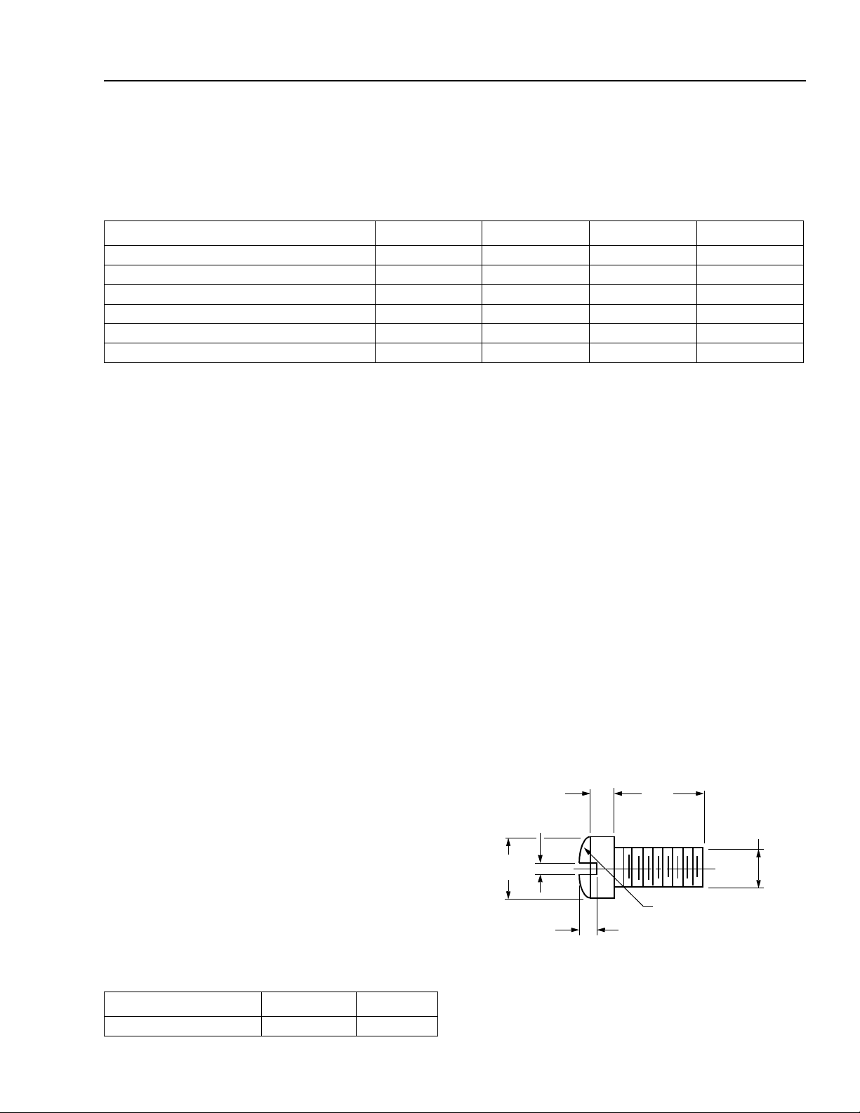
2. Mount four #2-56 screws with Fillister heads
(M2-3 mm) at the four screw hole locations (see
Outline Diagram). The Fillister head diameter must
not exceed 0.140 in. (3.55 mm). Do not apply more
than 1 in./lb. of torque to the screws.
Agere Systems employs a human-body model (HBM)
for ESD-susceptibility testing and protection-design
evaluation. ESD voltage thresholds are dependent on
the critical parameters used to define the model. A
standard HBM (resistance = 1.5 k¾, capacitance =
100 pF) is widely used and, therefore, can be used for
comparison purposes. The HBM ESD threshold presented here was obtained using these circuit parameters:
Parameter Value Unit
Human-body Model >400 V
Agere Systems Inc. 3
Figure 2. Fillister Head Screw
Page 4
D2570, D2526G, D2555 Wavelength-Selected Data Sheet, Rev. 3
Direct Modulated Isolated DFB Laser Module July 2001
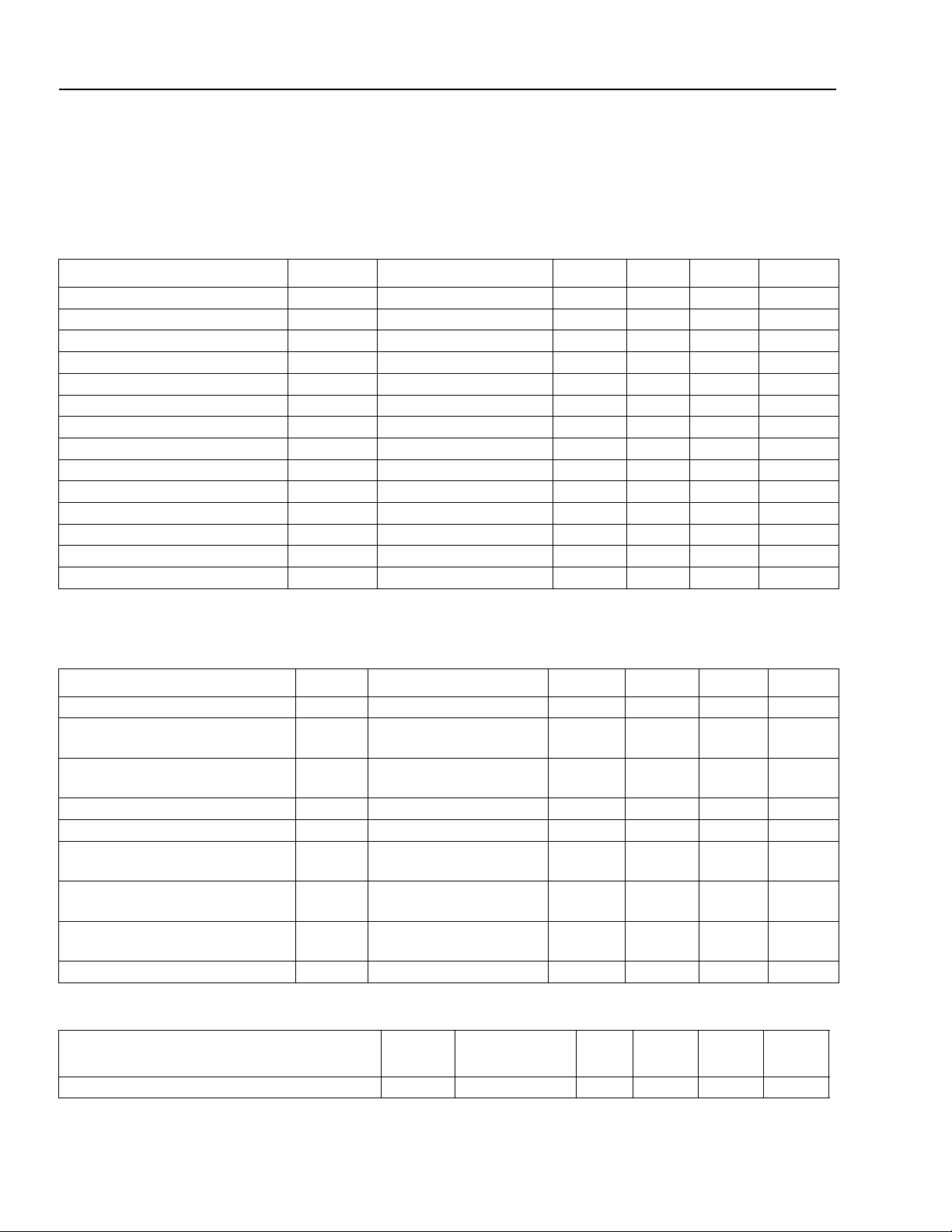
D2526 Characteristics
Minimum and maximum values are testing requirements. Typical values are characteristics of the device and are
the result of engineering e v aluations . Typical values are for inf ormation purposes only and are not part of the testing
requirements.
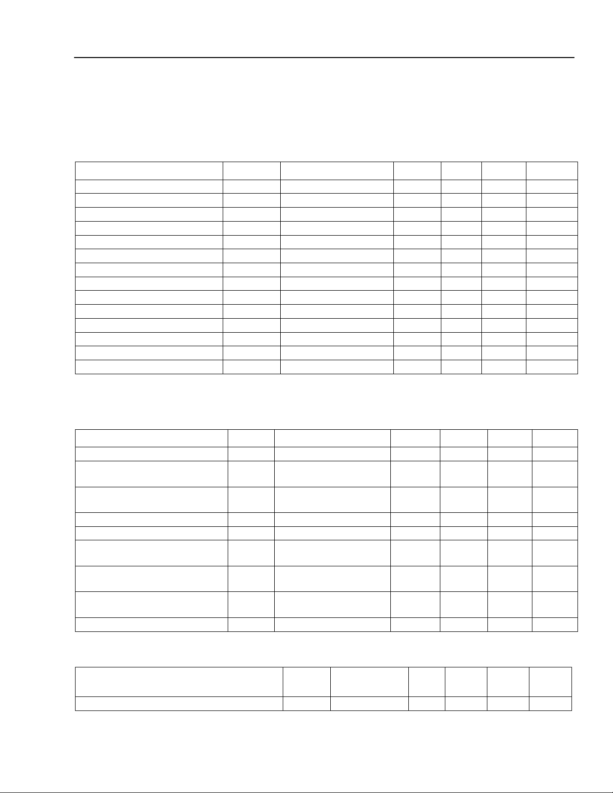
Table 1. Electrical Characteristics (at 25 °C laser temperature)
Parameter Symbol Test Conditions Min Typ Max Unit
Slope Efficiency η L
Threshold Current I
Laser Forward Voltage V
Laser Submount Temperature T
Monitor Reverse-bias Voltage* V
Monitor Current I
Monitor Dark Current I
Input Impedance Z
Thermistor Current I
Resistance Ratio
†
Thermistor Resistance R
TEC Current I
TEC Voltage V
TH
LF
LASER
RMON
RMON
D
IN
TC
— — 9.1 — 9.6 —
TH
TEC
TEC
TEC Capacity ∆TT
* Standard operating condition is 5.0 V reverse bias.
† Ratio of thermistor resistance at 0 °C to thermistor resistance at 50 °C.
F
= 2 mW (CW) 0.06 0.09 0.13 mW/mA
——1430mA
LF = 2 mW (CW) — 1.3 1.8 V
—20—30°C
—3510V
POL = 1 mW (CW) 0.1 0.3 1.5 mA
IF = 0, V
RMON
= 5 V — 0.01 0.1 µA
——25—Ω
— 10 — 100 µA
TL = 25 °C 9.5 — 10.5 kΩ
TL = 25 °C, TC = 70 °C — 0.6 1.0 A
TL = 25 °C, TC = 70°C — 1.3 2.0 V
C
= 70 °C — — 50 °C
Table 2. Optical Characteristics (at 25 °C laser temperature)
Parameter Symbol Test Conditions Min Typ Max Unit
Peak Optical Output Power P
Center Wavelength
(See Table 10.)
Line Width (3 dB full width) ∆λ Modulated at 2.5 Gbits/s
PEAK
λcT
—2.0——mW
L
= 25 °C
CW wavelength
1528.77 — 1610.06 nm
—210MHz
at rated power
Side-mode Suppression Ratio SMSR CW 30 — — dB
C
Optical Isolation — T
Wavelength Drift (EOL) ∆λ Tested over
= 0 °C to 70 °C 30 — — dB
——±0.1nm
25-year lifetime
Center Wavelength Drift with
C
/∆T
0 °C ≤ TC ≤ 70 °C — — 1 pm/°C
C
∆λ
Case Temperature
Wavelength Temperature Tuning
— — — 0.095 — nm/°C
Coefficient
C
Tracking Error — T
= –20 °C/25 °C/70 °C — — 1 dB
Table 3. Dispersion Performance
Parameter Symbol
Test
Conditions
Min Typ Max Unit
Dispersion Penalty for Extended Reach DP 1800 ps/nm — — 2.0 dB
4 Agere Systems Inc.
Page 5
Data Sheet, Rev . 3 D2570, D2526G, D2555 Wavelength-Selected
July 2001 Direct Modulated Isolated DFB Laser Module
D2555 Characteristics
Minimum and maximum values are testing requirements. Typical values are characteristics of the device and are
the result of engineering evaluations. Typical values are for information purposes only and are not part of the testing requirements.
Table 4. Electrical Characteristics (at 25 °C laser temperature)
Parameter Symbol Test Conditions Min Typ Max Unit
Slope Efficiency η L
Threshold Current I
Laser Forward Voltage V
Laser Submount Temperature T
Monitor Reverse-bias Voltage* V
Monitor Current I
Monitor Dark Curren t I
Input Impedance Z
Thermistor Current I
Resistance Ratio
†
Thermistor Resistance R
TEC Current I
TEC Voltage V
TH
LF
LASER
RMON
RMON
D
IN
TC
——9.1—9.6—
TH
TEC
TEC
TEC Capacity ∆TT
* Standard opera ti ng condition is 5.0 V reverse bias.
† Ratio of thermistor resistance at 0 °C to thermistor resistance at 50 °C.
F
= 2 mW (CW) 0.05 0.08 0.10 mW/mA
— — 12 35 mA
LF = 2 mW (CW) — 1.3 1.8 V
—20—30°C
—3510V
POL = 1 mW (CW) 0.1 0.3 1.9 mA
IF = 0, V
RMON
= 5 V — 0.01 0.1 µA
——25—Ω
— 10 — 100 µA
TL = 25 °C 9.5 — 10.5 kΩ
TL = 25 °C, TC = 70 °C — 0.6 1.0 A
TL = 25 °C, TC = 70°C — 1.3 2.0 V
C
= 70 °C — — 50 °C
Table 5. Optical Characteristics (at 25 °C laser temperature)
Parameter Symbol Test Conditions Min Typ Max Unit
Peak Optical Output Power P
Center Wavelength
PEAK
λcT
(See Table 11.)
Line Width (3 dB full width) ∆λ Modulated at 2.5 Gbits/s
—2.0——mW
L
= 25 °C
1528.77 — 1563.86 nm
CW wavelength
—210MHz
at rated power
Side-mode Suppression Ratio SMSR CW 30 — — dB
C
Optical Isolation — T
Wavelength Drift (EOL) ∆λ Tested over
= 0 °C to 75 °C 30 — — dB
——±0.1nm
25-year lifetime
Center Wavelength Drift with
C
/∆T
0 °C ≤ TC ≤ 75 °C — — 1 pm/°C
C
∆λ
Case Temperature
Wavelength Temperature Tuning
— — — 0.095 — nm/°C
Coefficient
C
Tracking Error — T
= –20 °C/25 °C/70 °C — — 1 dB
Table 6. Dispersion Performance
Parameter Symbol
Test
Conditions
Min Typ Max Unit
Dispersion Penalty for Extended Reach DP 3000 ps/nm — — 2.0 dB
Agere Systems Inc. 5
Page 6

D2570, D2526G, D2555 Wavelength-Selected Data Sheet, Rev. 3
Direct Modulated Isolated DFB Laser Module July 2001
D2570 Characteristics
Minimum and maximum values are testing requirements. Typical values are characteristics of the device and are
the result of engineering evaluations. Typical values are for information purposes only and are not part of the testing requirements.
Table 7. Electrical Characteristics (at 25 °C laser temperature)
Parameter Symbol Test Conditions Min Typ Max Unit
Slope Efficiency η L
Threshold Current I
Laser Forward Voltage V
Laser Submount Temperature T
Monitor Reverse-bias Voltage* V
Monitor Current I
Monitor Dark Current I
Input Impedance Z
Thermistor Current I
Resistance Ratio
†
Thermistor Resistance R
TEC Current I
TEC Voltage V
TH
LF
LASER
RMON
RMON
D
IN
TC
— — 9.1 — 9.6 —
TH
TEC
TEC
TEC Capacity ∆TT
* Standard operating condition is 5.0 V reverse bias.
† Ratio of thermistor resistance at 0 °C to thermistor resistance at 50 °C.
F
= 10 mW (CW) 0.12 0.15 0.2 mW/mA
——1425mA
LF = 10 mW (CW) — 1.3 1.8 V
—20—30°C
—3510V
POL = 5 mW (CW) 0.25 0.7 1.25 mA
IF = 0, V
RMON
= 5 V — 0.01 0.1 µA
——25—Ω
—10—100µA
TL = 25 °C 9.5 — 10.5 kΩ
TL = 25 °C, TC = 70 °C — 0.6 1.0 A
TL = 25 °C, TC = 70°C — 1.3 2.0 V
C
= 70 °C — — 50 °C
Table 8. Optical Characteristics (at 25 °C laser temperature)
Parameter Symbol Test Conditions Min Typ Max Unit
Peak Optical Output Power P
Center Wavelength
PEAK
λcT
(See Table 12.)
Line Width (3 dB full width) ∆λ Modulated at 2.5 Gbits/s
—10——mW
L
= 25 °C
1528.77 — 1610.06 nm
CW wavelength
—210MHz
at rated power
Side-mode Suppression Ratio SMSR CW 30 — — dB
C
Optical Isolation — T
Wavelength Drift (EOL) ∆λ Te sted over
= 0 °C to 70 °C 30 — — dB
——±0.1nm
25-year lifetime
Center Wavelength Drift with
C
/∆T
0 °C ≤ TC ≤ 70 °C — — 1 pm/°C
C
∆λ
Case Temperature
Wavelength Temperature Tuning
— — — 0.095 — nm/°C
Coefficient
C
Tracking Error — T
= –20 °C/25 °C/70 °C — — 1 dB
Table 9. Dispersion Performance
Parameter Symbol
Test
Conditions
Min Typ Max Unit
Dispersion Penalty for Extended Reach DP 1800 ps/nm — — 2.5 dB
6
6 Agere Systems Inc.
Page 7

Data Sheet, Rev . 3 D2570, D2526G, D2555 Wavelength-Selected
)
July 2001 Direct Modulated Isolated DFB Laser Module
Outline Drawings
Dimensions are in inches and (millimeters).
0.605
(15.37)
MAX
0.365
(9.27)
MAX
0.500 (12.70)
MIN
0.500
(12.70)
0.350
(8.89)
0.105 (2.67) DIA
TYP (4) PLACES
0.180 (4.56)
0.056 (1.42)
1.025 (26.04)
0.020 (0.51) TYP
0.100 (2.54) TYP
0.820 (20.83)
0.700 (17.78)
PIN 1
TRADEMARK, CODE, LASER SERIAL NUMBER,
AND DATE CODE IN APPROX. AREA SHOWN
STRAIN
RELIEF
~
0.078 (1.98)
PIN 14
0.213 (5.40) TYP
39.37 (1000.00)
2.03 (51.6)
0.863 (21.91)
0.575 (14.61)
MIN
0.10
(2.5)
0.10 ± 0.002
(2.54 ± 0.051)
0.036
(0.91)
0.260 (6.60)
0.200
(5.08
0.215
(5.47)
REF
0.215 (5.45)
1.180 (29.97)
HEAT SINK
0.030 (0.75)
1-520.g
Agere Systems Inc. 7
Page 8

D2570, D2526G, D2555 Wavelength-Selected Data Sheet, Rev. 3
Direct Modulated Isolated DFB Laser Module July 2001
Ordering Information
Table 10. Ordering Information D2526G (FC-PC Connector)
Device
Code
ITU Freq.
(THz)
Center
Wavelength
(nm)
Comcode
D2526G61 196.1 1528.77 108221599
D2526G60 196.0 1529.55 108221581
D2526G59 195.9 1530.33 108221573
D2526G58 195.8 1531.12 108221565
D2526G57 195.7 1531.90 108221557
D2526G56 195.6 1532.68 108003658
D2526G55 195.5 1533.47 108003641
D2526G54 195.4 1534.25 108003633
D2526G53 195.3 1535.04 108003625
D2526G52 195.2 1535.82 108003617
D2526G51 195.1 1536.61 108003609
D2526G50 195.0 1537.40 108003591
D2526G49 194.9 1538.19 108003583
D2526G48 194.8 1538.98 108003575
D2526G47 194.7 1539.77 108003567
D2526G46 194.6 1540.56 108003559
D2526G45 194.5 1541.35 108003542
D2526G44 194.4 1542.14 108003534
D2526G43 194.3 1542.94 108003526
D2526G42 194.2 1543.73 108003518
D2526G41 194.1 1544.53 108003500
D2526G40 194.0 1545.32 108003492
D2526G39 193.9 1546.12 108003484
D2526G38 193.8 1546.92 108003476
D2526G37 193.7 1547.72 108003468
D2526G36 193.6 1548.51 108003450
D2526G35 193.5 1549.32 108003443
D2526G34 193.4 1550.12 108003435
D2526G33 193.3 1550.92 108003427
D2526G32 193.2 1551.72 108003419
D2526G31 193.1 1552.52 108003385
D2526G30 193.0 1553.33 108003377
D2526G29 192.9 1554.13 108003369
D2526G28 192.8 1554.94 108003351
D2526G27 192.7 1555.75 108003344
D2526G26 192.6 1556.55 108003336
D2526G25 192.5 1557.36 108003328
D2526G24 192.4 1558.17 108003310
D2526G23 192.3 1558.98 108003302
D2526G22 192.2 1559.79 108003294
D2526G21 192.1 1560.61 108003286
Device
D2526G19 191.9 1562.23 108003260
D2526G18 191.8 1563.05 108221540
D2526G17 191.7 1563.86 108221532
D2526G916 191.6 1564.68 108512526
D2526G915 191.5 1565.50 108512518
D2526G914 191.4 1566.31 108479858
D2526G913 191.3 1567.13 108479841
D2526G912 191.2 1567.95 108479833
D2526G911 191.1 1568.77 108479825
D2526G910 191.0 1569.59 108479817
D2526G909 190.9 1570.42 108479809
D2526G908 190.8 1571.24 108480369
D2526G907 190.7 1572.06 108480351
D2526G906 190.6 1572.89 108480344
D2526G905 190.5 1573.71 108479791
D2526G904 190.4 1574.54 108479783
D2526G903 190.3 1575.37 108479775
D2526G902 190.2 1576.20 108479767
D2526G901 190.1 1577.02 108479759
D2526G900 190.0 1577.85 108479742
D2526G899 189.9 1578.69 108480336
D2526G898 189.8 1579.52 108479734
D2526G897 189.7 1580.35 108479700
D2526G896 189.6 1581.18 108479692
D2526G895 189.5 1582.02 108479684
D2526G894 189.4 1582.85 108479676
D2526G893 189.3 1583.69 108479668
D2526G892 189.2 1584.53 108479650
D2526G891 189.1 1585.36 108479643
D2526G890 189.0 1586.20 108479635
D2526G889 188.9 1587.04 108479627
D2526G888 188.8 1587.88 108479619
D2526G887 188.7 1588.72 108479601
D2526G886 188.6 1589.57 108479585
D2526G885 188.5 1590.41 108479577
D2526G884 188.4 1591.25 108479569
D2526G883 188.3 1592.10 108479551
D2526G882 188.2 1592.95 108479544
D2526G881 188.1 1593.79 108479536
D2526G880 188.0 1594.64 108479528
D2526G879 187.9 1595.49 108479510
Code
ITU Freq.
(THz)
Center
Wavelength
(nm)
Comcode
8 Agere Systems Inc.
Page 9

Data Sheet, Rev . 3 D2570, D2526G, D2555 Wavelength-Selected
July 2001 Direct Modulated Isolated DFB Laser Module
Ordering Information
Table 10. Ordering Information D2526G (FC-PC Connector)
Device
Code
D2526G20 192.0 1561.42 108003278
D2526G877 187.7 1597.19 108479494 D2526G869 186.9 1604.33 108578220
D2526G876 187.6 1598.04 108479486 D2526G868 186.8 1604.88 108578204
D2526G875 187.5 1598.89 108479478 D2526G867 186.7 1605.74 108578196
D2526G874 187.4 1599.75 108479460 D2526G866 186.6 1606.60 108578188
D2526G873 187.3 1600.60 108479452 D2526G865 186.5 1607.47 108578162
D2526G872 187.2 1601.45 108479445 D2526G864 186.4 1608.33 108578154
D2526G871 187.1 1602.31 108479437 D2526G863 186.3 1609.19 108578105
D2526G870 187.0 1603.17 108578246 D2526G862 186.2 1610.06 108578097
Table 11. Ordering Information D2555G (FC-PC Connector)
Device
Code
D2555G61 196.1 1528.77 108309113 D2555G38 193.8 1546.92 108167008
D2555G60 196.0 1529.55 108309105 D2555G37 193.7 1547.72 108166992
D2555G59 195.9 1530.33 108309089 D2555G36 193.6 1548.51 108166984
D2555G58 195.8 1531.12 108309071 D2555G35 193.5 1549.32 108166976
D2555G57 195.7 1531.90 108309063 D2555G34 193.4 1550.12 108166968
D2555G56 195.6 1532.68 108167180 D2555G33 193.3 1550.92 108166950
D2555G55 195.5 1533.47 108167172 D2555G32 193.2 1551.72 108166943
D2555G54 195.4 1534.25 108167164 D2555G31 193.1 1552.52 108166935
D2555G53 195.3 1535.04 108167156 D2555G30 193.0 1553.33 108166927
D2555G52 195.2 1535.82 108167149 D2555G29 192.9 1554.13 108166877
D2555G51 195.1 1536.61 108167131 D2555G28 192.8 1554.94 108166851
D2555G50 195.0 1537.40 108167123 D2555G27 192.7 1555.75 108166836
D2555G49 194.9 1538.19 108167115 D2555G26 192.6 1556.55 108166810
D2555G48 194.8 1538.98 108167107 D2555G25 192.5 1557.36 108166794
D2555G47 194.7 1539.77 108167099 D2555G24 192.4 1558.17 108166786
D2555G46 194.6 1540.56 108167081 D2555G23 192.3 1558.98 108166760
D2555G45 194.5 1541.35 108167073 D2555G22 192.2 1559.79 108166745
D2555G44 194.4 1542.14 108167065 D2555G21 192.1 1560.61 108166737
D2555G43 194.3 1542.94 108167057 D2555G20 192.0 1561.42 108166695
D2555G42 194.2 1543.73 108167040 D2555G19 191.9 1562.23 108166687
D2555G41 194.1 1544.53 108167032 D2555G18 191.8 1563.05 108309972
D2555G40 194.0 1545.32 108167024 D2555G17 191.7 1563.86 108309964
D2555G39 193.9 1546.12 108167016
ITU Freq.
(THz)
ITU Freq.
(THz)
(continued)
Center
Wavelength
(nm)
Center
Wavelength
(nm)
Comcode
Comcode
(continued)
Device
Code
ITU Freq.
(THz)
Center
Wavelength
Comcode
(nm)
D2526G878 187.8 1596.34 108479502
Device
Code
ITU Freq.
(THz)
Center
Wavelength
(nm)
Comcode
Agere Systems Inc. 9
Page 10

D2570, D2526G, D2555 Wavelength-Selected Data Sheet, Rev. 3
Direct Modulated Isolated DFB Laser Module July 2001
Orderin g Information
Table 12. Ordering Information D2570H
Device
Code
D2570H61 196.1 1528.77 108278425 D2570H18 191.8 1563.05 108277369
D2570H60 196.0 1529.55 108278417 D2570H17 191.7 1563.86 108277351
D2570H59 195.9 1530.33 108278409 D2570H916 191.6 1564.68 108512500
D2570H58 195.8 1531.12 108278391 D2570H915 191.5 1565.50 108512492
D2570H57 195.7 1531.90 108278383 D2570H914 191.4 1566.31 108488149
D2570H56 195.6 1532.68 108277914 D2570H913 191.3 1567.13 108488131
D2570H55 195.5 1533.47 108277500 D2570H912 191.2 1567.95 108488123
D2570H54 195.4 1534.25 108277492 D2570H911 191.1 1568.77 108488115
D2570H53 195.3 1535.04 108277484 D2570H910 191.0 1569.59 108488107
D2570H52 195.2 1535.82 108277476 D2570H909 190.9 1570.42 108488099
D2570H51 195.1 1536.61 108277468 D2570H908 190.8 1571.24 108488081
D2570H50 195.0 1537.40 108277450 D2570H907 190.7 1572.06 108488073
D2570H49 194.9 1538.19 108277443 D2570H906 190.6 1572.89 108488065
D2570H48 194.8 1538.98 108277435 D2570H905 190.5 1573.71 108488057
D2570H47 194.7 1539.77 108277427 D2570H904 190.4 1574.54 108488040
D2570H46 194.6 1540.56 108277419 D2570H903 190.3 1575.37 108488032
D2570H45 194.5 1541.35 108277393 D2570H902 190.2 1576.20 108488024
D2570H44 194.4 1542.14 108177924 D2570H901 190.1 1577.02 108488016
D2570H43 194.3 1542.94 108177916 D2570H900 190.0 1577.85 108488008
D2570H42 194.2 1543.73 108177908 D2570H899 189.9 1578.69 108487992
D2570H41 194.1 1544.53 108177890 D2570H898 189.8 1579.52 108487984
D2570H40 194.0 1545.32 108177882 D2570H897 189.7 1580.35 108487976
D2570H39 193.9 1546.12 108177874 D2570H896 189.6 1581.18 108487968
D2570H38 193.8 1546.92 108177866 D2570H895 189.5 1582.02 108487950
D2570H37 193.7 1547.72 108177858 D2570H894 189.4 1582.85 108487943
D2570H36 193.6 1548.51 108177841 D2570H893 189.3 1583.69 108487935
D2570H35 193.5 1549.32 108177833 D2570H892 189.2 1584.53 108487927
D2570H34 193.4 1550.12 108177153 D2570H891 189.1 1585.36 108487919
D2570H33 193.3 1550.92 108177825 D2570H890 189.0 1586.20 108487901
D2570H32 193.2 1551.72 108177809 D2570H889 188.9 1587.04 108487893
D2570H31 193.1 1552.52 108177791 D2570H888 188.8 1587.88 108487885
D2570H30 193.0 1553.33 108177783 D2570H887 188.7 1588.72 108487877
D2570H29 192.9 1554.13 108177767 D2570H886 188.6 1589.57 108487869
D2570H28 192.8 1554.94 108177759 D2570H885 188.5 1590.41 108487851
D2570H27 192.7 1555.75 108177742 D2570H884 188.4 1591.25 108487844
D2570H26 192.6 1556.55 108177734 D2570H883 188.3 1592.10 108487836
D2570H25 192.5 1557.36 108177726 D2570H882 188.2 1592.95 108487828
D2570H24 192.4 1558.17 108177718 D2570H881 188.1 1593.79 108487810
D2570H23 192.3 1558.98 108177700 D2570H880 188.0 1594.64 108487802
D2570H22 192.2 1559.79 108177692 D2570H879 187.9 1595.49 108487794
D2570H21 192.1 1560.61 108177684 D2570H878 187.8 1596.34 108487786
D2570H20 192.0 1561.42 108277385 D2570H877 187.7 1597.19 108487778
D2570H19 191.9 1562.23 108277377 D2570H876 187.6 1598.04 108487760
ITU Freq.
(THz)
(
continued)
Center
Wavelength
(nm)
®
(
Ferrule)
ST
Comcode Device
Code
ITU Freq.
(THz)
Center
Wavelength
(nm)
Comcode
10 Agere Systems Inc.
Page 11

Data Sheet, Rev . 3 D2570, D2526G, D2555 Wavelength-Selected
July 2001 Direct Modulated Isolated DFB Laser Module
Ordering Information
Table 12. Ordering Information D2570H
Device
Code
D2570H875 187.5 1598.89 108487752
D2570H874 187.4 1599.75 108487745
D2570H873 187.3 1600.60 108487737
D2570H872 187.2 1601.45 108487729
D2570H871 187.1 1602.31 108487711
D2570H870 187.0 1603.17 108578659 D2570H863 186.3 1609.19 108578402
D2570H869 186.9 1604.33 108578642 D2570H862 186.2 1610.06 108578394
ITU Freq.
(THz)
(continued)
Center
Wavelength
(nm)
Ferrule)
(
ST
Comcode Device
(continued)
Code
D2570H868 186.8 1604.88 108578634
D2570H867 186.7 1605.74 108578618
D2570H866 186.6 1606.60 108578469
D2570H865 186.5 1607.47 108578428
D2570H864 186.4 1608.33 108578410
ITU Freq.
(THz)
Center
Wavelength
(nm)
Comcode
Laser Safety Information
Class IIIb Laser Product
FDA/CDRH Class IIIb laser product. All versions are Class IIIb laser products per CDRH, 21 CFR 1040 Laser
Safety requirements. The device has been classified with the FDA under accession number 8720010.
This product complies with 21 CFR 1040.10 and 1040.11.
8.3 µm/125 µm single-mode fiber pigtail with 900 µm tight buffer jacket and connector
Wavelength = 1.5 µm
Maximum power = 40 mW
Because of size constraints, laser saf ety labeling (includi ng an FD A Class IIIb label) is not affix ed to the module b ut
attached to the outside of the shipping carton.
Product is not shipped with power supply.
Caution: Use of controls, adjustments, and procedures other than those specified herein may result in
hazardous laser radiation exposure .
DANGER
INVISIBLE LASER RADIATION
IS EMITTED FROM THE END
OF FIBER OR CONNECTOR
Avoid direct exposure to beam
Do not view beam directly with
optical instruments
INVISIBLE LASER RADIATION EMITTED FROM END OF FIBER OR CONNECTOR
Avoid exposure to beam
Class IIIb Laser Product FDA/CDRH, 21 CFR 1040 Max. Output: 40 mW Wavelength: 1.5 µm
Agere Systems Inc. 11
Page 12

D2570, D2526G, D2555 Wavelength-Selected Data Sheet, Rev. 3
Direct Modulated Isolated DFB Laser Module July 2001
For additional information, cont ac t your Agere S y s tems A cc ount M anager or the following:
INTERNET:
E-MAIL:
N. AMERICA: Agere Systems Inc., 555 Union Boulevard, Room 30L-15P-BA, Allentown, PA 1810 9-3286
ASIA PACIFIC: Agere Systems Singapore Pte. Ltd., 77 Science Park Drive, #03-18 Cintech III, Singapore 118256
CHINA: Agere Systems (Shanghai) Co., Ltd., 33/F Jin Mao Tower, 88 Century Boulevard Pudong, Shanghai 200121 PRC
JAPAN: Agere Systems Japan Ltd., 7-18, Higashi-Gotanda 2-chome, Shinagawa-ku, Tokyo 141, Japan
EUROPE: Data Requests: DATALINE:
Agere Systems Inc. reserves the right to make changes to the product(s) or information contained herein without notice. No liability is assumed as a result of their use or application.
is a registered trademark of Agere Systems Inc.
ST
Copyright © 2001 Agere Systems Inc.
All Rights Reserved
July 2001
DS00-165OPTO-3 (Replaces DS00-165OPTO-2)
http://www.agere.com
docmaster@agere.com
1-800-372-2447
Tel. (65) 778 8833
Tel. (86) 21 50471212
Tel. (81) 3 5421 1600
Tec hni c al Inquiries: OPTOELECTRONICS MARKETING:
, FAX 610-712-4106 (In CANADA:
, FAX (65) 777 7495
, FAX (86) 21 50472266
, FAX (81) 3 5421 1700
Tel. (44) 7000 582 368
1-800-553-2448
, FAX (44) 1189 328 148
, FAX 610-712-4106)
(44) 1344 865 900
(Ascot UK)
 Loading...