

AGERE P172ABCJ, P172PCCF, P172PCCJ, P172PCCS, P172PBCJ Datasheet
...
P172-Type Receiver
Advance Data Sheet
August 2001
Features
■
Low-profile, 8-lead mini-DIL or gull-wing style
package:
— Suitable for SONET/SDH applications
■
Metal package:
— Offers superior shielding for high noise
immunity
■
Planar structure for high reliability
■
Operating wavelength range:
— 1.25 µm—1.6 µm
The P172-Type PIN/Preamp and APD/Preamp receivers are
available in a mini-DIL package (top) or a gull-wing package
(bottom).
■
Available in 8 µm core single-mode fiber or
62.5 µm core multimode fiber pigtails
■
Wide operating temperature range:
— APD/PIN, –40 °C to +85 °C
■
Scheduled to be qualified according to
Technologies
■
Typical sensitivity:
™ GR-468-CORE
Telcordia
— APD, –32 dBm
— PIN, –23 dBm
■
Thermistor in APD version
Applications
■
Long-reach or metro SONET OC-48 and
SDH STM-16, or multidata-rate telecommunications applications
■
SONET/SDH receivers and transponders
■
Line terminal equipment
Benefits
■
Compact size
■
Easily board mounted
Advance Data Sheet
P172-Type Receiver August 2001
DATA
Description
The P172-type receiver consists of a PIN or APD coupled to a single-mode or multimode fiber pigtail and a
linear preamplifier. Both the PIN and APD are rear-illuminated planar diode structures with a low-capacitance
active area for maximum responsivity and speed.
This device incorporates the new Laser 2000 manufacturing process from the Optoelectronics Products unit
of Agere Systems Inc. Laser 2000 is a low-cost platform that targets high-volume manufacturing and tight
product distributions on all optical subassemblies. This
platform incorporates an advanced optical design that
is produced on Agere Systems’ highly automated production lines. The Laser 2000 platform is qualified for
central office and uncontrolled environments, and can
be used for applications requiring high performance
and low cost.
GND GND
DATA V
4321
56
DATA
GND GND
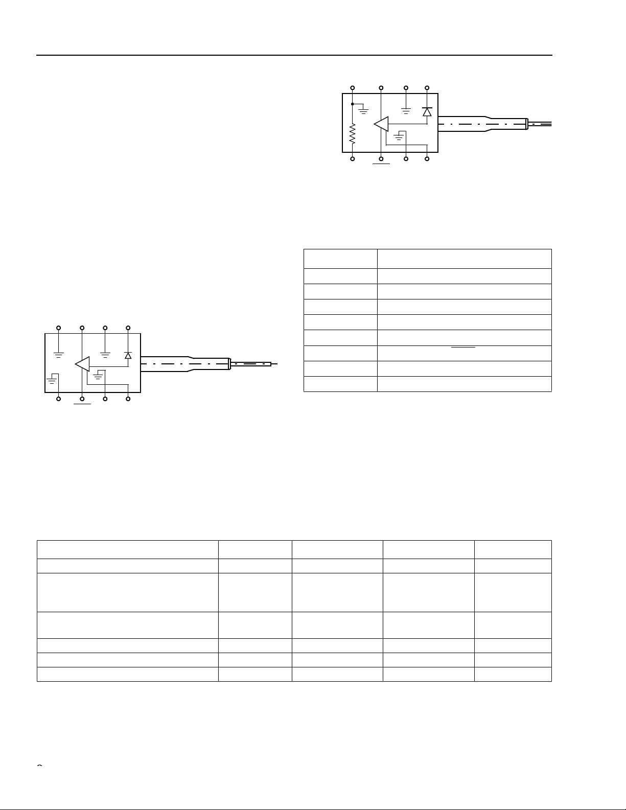
Figure 1. P172P PIN/Preamp Schematic (Top View)
PD
78
V
CC
1-902(F).b
GND
4321
5678
THERMISTOR
Figure 2. P172A APD/Preamp (Top View)
Table 1. P172-Type PIN/Preamp and APD/Preamp
Pin Descriptions
Pin Number Description
1 Photodiode Bias
2 Case Ground
3DATA*
4 Case Ground
5 Thermis tor /Cas e Grou nd
6DATA
7 Case Ground
8V
* Logic high when light is on.
† Thermistor in APD version; case ground in PIN version
‡ Logic low when light is on.
DATA
GND V
GND
PD
V
CC
‡
CC
1-902(F).c
†
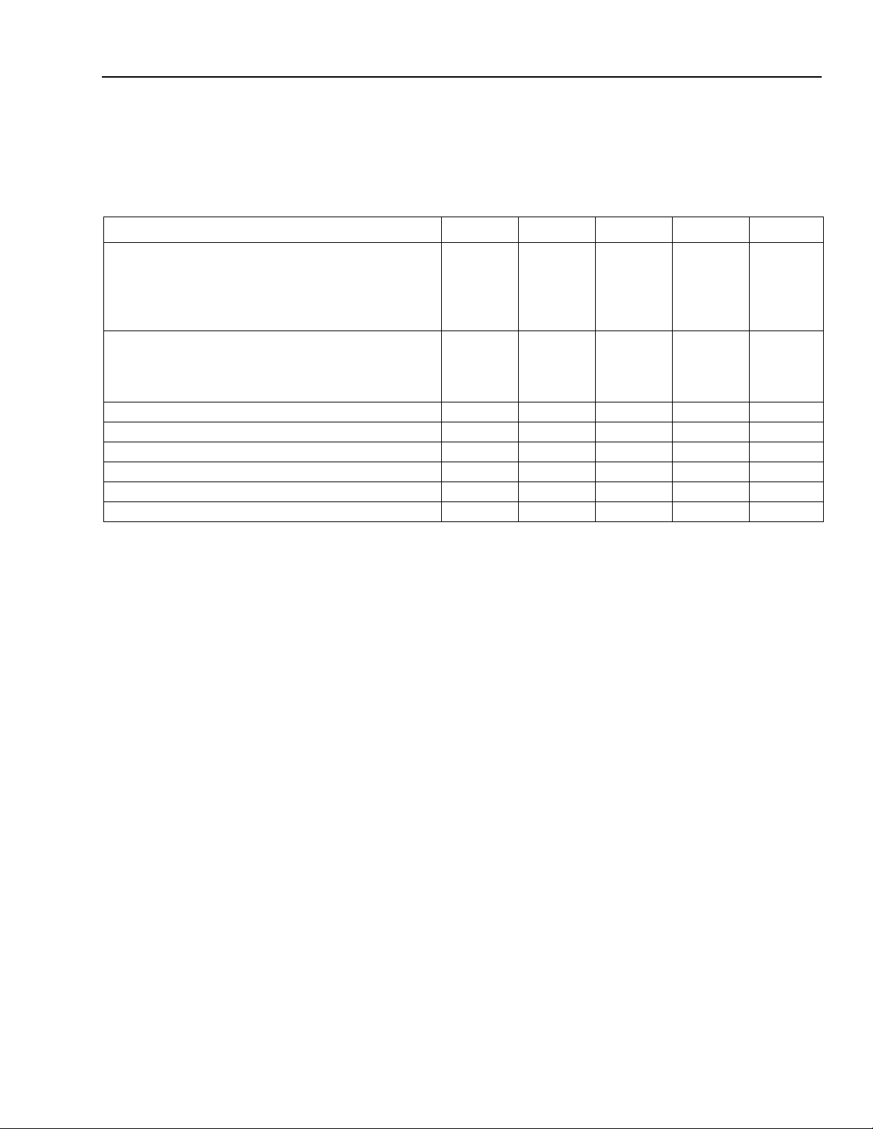
Absolute Maximum Ratings
Stresses in excess of the absolute maximum ratings can cause permanent damage to the device. These are absolute stress ratings only. Functional operation of the device is not implied at these or any other conditions in excess
of those given in the operational sections of the data sheet. Exposure to absolute maximum ratings for extended
periods can adversely affect device reliability.
Parameter Symbol Min Max Unit
Positive Supply Voltage V
Optical Input Power:
APD
PIN
Operating Case Temperature Range:
APD/PIN T
Storage Temperature Range T
Lead Soldering Temperature — — 250 °C
Lead Soldering Time — — 10 s
CC
IN
P
IN
P
C
stg
–0.5 4.0 V
—
—
0
8.0
dBm
dBm
–40 85 °C
–40 85 °C
2
2
Agere System s Inc.
Advance Data Sheet
August 2001 P172-Type Receiver
Electrical Characteristics
Minimum and maximum values specified over operating case temperature range and end of life (EOL), and typical
values are for 25 °C and beginning of life (BOL), unless otherwise specified
Table 2. Electrical Characteristic
Parameter Symbol Min Typ Max Unit
dc Power Supply Voltages:
Positive Supply
APD Operating Bias Voltage
V
V
APD Operating Voltage Temperature Coefficient
PIN Operating Bias Voltage
V
dc Power Supply Currents:
Positive Supply
APD Bias Supply at V
PIN Bias Supply at V
OP
OP
I
I
I
dc Power Dissipation P
Small Signal (<10 µA) Transimpedance T
Input Noise Current (100 kHz—2 GHz) N
Output Return Loss (130 MHz—5 GHz) S
3 dB Bandwidth f
Thermistor resistance at 25 °C* R
CC
OP
—
OP
CC
APD
PIN
DISS
z
rms
22
C
TH
3.15
45
0.07
3.0
—
—
—
3.3
—
—
5.0
55
—
—
3.45
70
0.14
15
101
4
4
— 200 350 mW
1.7 2.5 3.1 kΩ
— 322 466 nArms
— –15 –9 dB
1.7 2.0 — GHz
9.5 10 10.5 kΩ
V
V
V/°C
V
mA
mA
mA
* The resistance of the thermistor is inversely proportional to the temperature. The temperature can be calculated from the resistance value
using the Steinhart-Hart equation: 1/T = A + B ln(R) + C ln(R)
C = 4.5421 x 10
–8
.
3
;
where A, B, and C are constants: A = 1.0267 x 10
–3
,
B = 2.565 x 10
–4
,
Agere Systems Inc.
3
 Loading...