

AGERE A1112PC, A1112PB, A1112NC, A1112NB Datasheet
A1112 High-Power 1550 nm DFB Source Lasers
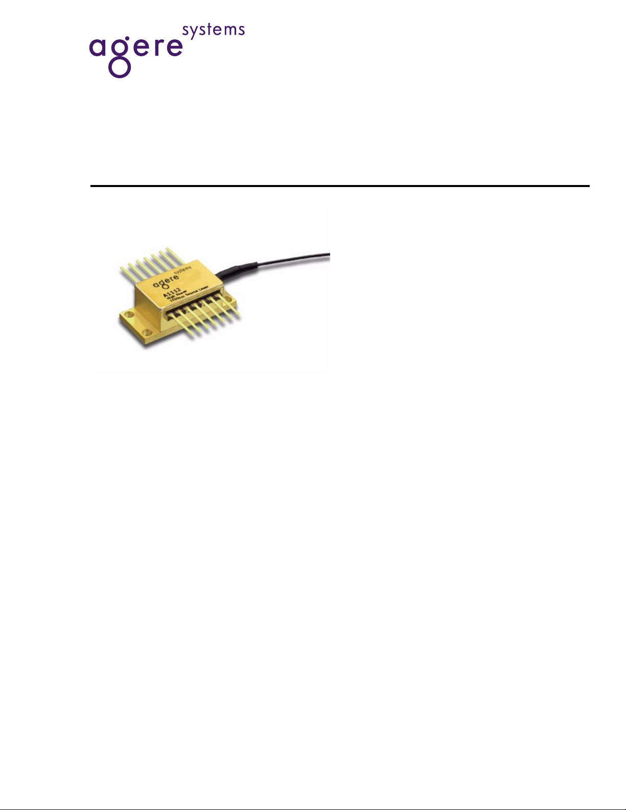
Description
The A1112 1550 nm DFB laser modules are highpower devices in a 14-pin butterfly package with a
thermoelectric cooler and monitor photodiode. The
lasers are designed to be used in conjunction with
commercially available external modulators for highperformance analog and digital applications. Agere
Systems Inc. offers modules with 30 mW or 40 mW
output power coupled into polarization-preserving
fiber. The A1112 operates with positive or negative
bias.
Data Sheet
January 2001
Features
■
High fiber-coupled power, 30 mW and 40 mW
■
Narrow linewidth, <3 MHz
■
Low relative intensity noise, < –162 dB/Hz
■
Coupled to polarization-preserving (PANDA-type
fiber)
Applications
■
Externally modulated CATV transmitters
■
Externally modulated analog and digital communication links

Data Sheet
A1112 High-Power 1550 nm DFB Source Lasers January 2001
Absolute Maximum Ratings
Stresses in excess of the absolute maximum ratings can cause permanent damage to the device. These are absolute stress ratings only. Functional operation of the device is not implied at these or any other conditions in excess
of those given in the operational sections of the data sheet. Exposure to absolute maximum ratings for extended
periods can adversely affect device reliability.
Parameter Symbol Min Max Unit
Operating Case Temperature Range T
C
Storage Temperature Range Tstg –40 70 °C
Forward Current (Laser)
I
F
A1112PB, A1112NB
A1112PC, A1112NC
Reverse Voltage (Laser) V
Photodiode Reverse Voltage V
TEC Voltage V
TEC Current
RPD
TEC
I
TEC
R
Cooling
Heating
–20 65 °C
—
—
275
400
mA
mA
—2.0V
—10V
—2.0V
—
—
1.8
1.5
A
A
Electrical/Optical Characteristics
Table 1. Optical Characteristics
Parameter Symbol Conditions Min Max Unit
Optical Output Power
A1112PB, A1112NB
A1112PC, A1112NC
Center Wavelength λ
Linewidth (FWHM) ∆
Side Mode Suppression Ratio SMSR I
Relative Intensity Noise RIN l
Operating Current I
Threshold Current I
Forward Voltage V
Optical Isolation — –20 °C to +65°C 30 — dB
Polarization Extinction Ratio T
Reverse Voltage V
Table 2. Electrical Characteristics
Parameter Symbol Condition Min Max Unit
Monitor Photodiode Reverse Voltage V
Monitor Photodiode Current I
TEC Current I
TEC Voltage V
Thermistor Resistance R
(25 °C Case Temperature)
P
O
C
V
40 MHz to 860 MHz
OP
TH
F
E/TM
R
From fiber end, I
RMPD
MPD
TEC
TEC
TH
∆T = 40 °C — 1.8 A
∆T = 40 °C — 2.2 V
25 °C 9.0 11.0 kΩ
—
—
I
OP
I
OP
OP
,
OP
30
40
—
—
1540 1560 nm
—3MHz
30 — dB
— –162 dBc/Hz
— — 250/350 mA
— — 35/40 mA
— — 2.5/3.0 V
OP
20 — dB
——2.0V
Iop — 10 V
— 40 2000 µA
mW
mW
2
Agere Systems Inc.
 Loading...