

AGERE 2623Y, 2623N, 2623CSA, 2623CS Datasheet
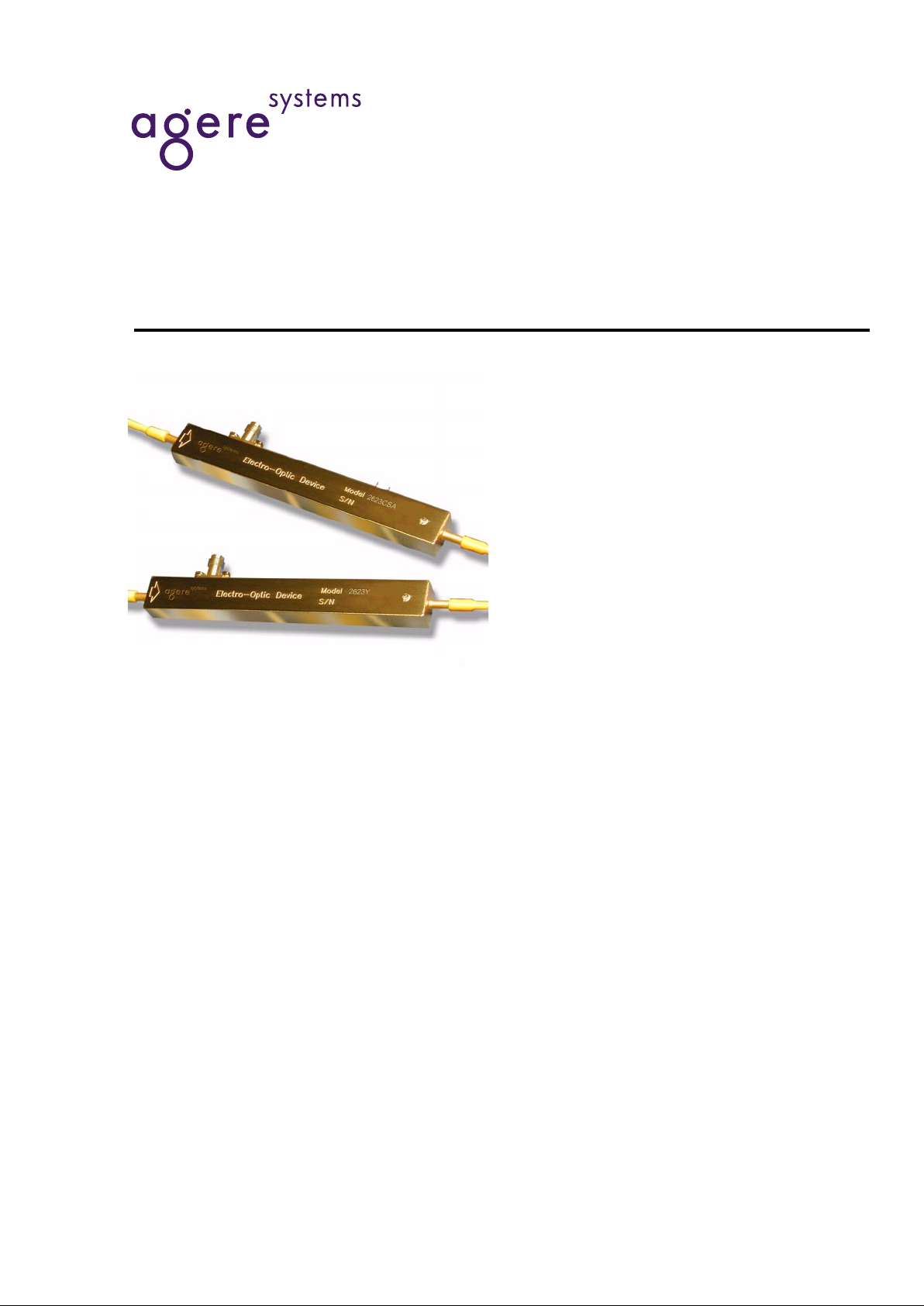
10 Gbits/s Lithium Niobate Electro-Optic Modulator
Data Sheet
May 2001
The Lithium Niobate Modulators include three single-drive
modulators (2623N, 2623Y, 2623CS) and a single-drive modulator with an integrated attenuator (2623CSA). All devices are
capable of modulation rates up to 10 Gbits/s.
Features
■
Ti-diffusion process
■
Single-drive technology
■
C- and L-band models
■
Slim, hermetic package
■
Bandwidths up to 10 GHz
■
Operational over a temperature range of 0 °C to
70 °C
■
43 Ω design for minimal electrical reflections
■
Angled interfaces for minimal optical reflections
■
Integrated optical attenuator available on
10 Gbits/s modulator (2623CSA)
■
Tested to
Telcordia Te chnologies
* 468
Benefits
■
Excellent long-term bias stability
■
Internal polarizer
■
Low modulation voltages
Applications
■
Digital high-speed telecommunications:
— SONET: OC-1 through OC-192
— SDH: STM-16, STM-64
— Undersea communications
■
Internet data communications
■
SONET/SDH test equipment
*
Telcordia Technologies
is a trademark of Telcordia Technologies,
Inc.
Data Sheet
10 Gbits/s Lithium Niobate Electro-Optic Modulator May 2001
22 Agere Systems Inc.
Description
The 10 Gbits/s Electro-Optic Modulator is designed for
long-wavelength, single-mode external amplitude modulation applications. It uses an integrated MachZehnder configuration to convert single polarization
CW light from a semiconductor (DFB) laser into a timevarying optical output signal. Agere Systems Inc. also
offers a 10 mW CW laser with polarization-maintaining
fiber (D2525P) to use as a source for the modulator.
The Ti-diffusion process is a standard feature on all
modulator devices. The 2623N, 2623Y, and 2623CS
are single-drive, 10 Gbits/s modulators; the 2623CSA
is a single-drive, 10 Gbits/s modulator with an attenuating section. Variable attenuation to >19 dB is achieved
through a dc bias voltage.
The package is hermetic to protect the LiNbO
3
die from
the environment. Novel processing techniques now
make it possible to achieve 20-year operation with little
drift in the dc bias point. The modulator is tested to, and
meets the intent of TR-NWT-00468.
Other standard features include PANDA-type polarization-maintaining fiber (PMF) for the optical input (all
codes) and output (2623N, 2623Y, and 2623C) fiber
with FC-type connectors that are keyed to the axis of
polarization. Custom designs are available.
Absolute Maximum Ratings
Stresses in excess of the absolute maximum ratings can cause permanent damage to the device. These are absolute stress ratings only. Functional operation of the device is not implied at these or any other conditions in excess
of those given in the operational sections of the data sheet. Exposure to absolute maximum ratings for extended
periods can adversely affect device reliability.
Parameter Symbol Min Max Unit
Storage Temperature T
stg
–40 85 °C
Optical Input Power @ 1.5 µm
P
IN
—
30 mW
RF Voltage (peak to peak) V
RF
—
10 V
dc Voltage (RF input) V
dcRF
–20 20 V
dc Voltage (Attenuator input) V
dcATT
–25 25 V
Operating Temperature T
OP
070°C
Data Sheet
May 2001 10 Gbits/s Lithium Niobate Electro-Optic Modulator
3
Agere Systems Inc.
Optical/Electrical Characteristics
* Bandwidth stated is electrical-optical-electrical as determined by the ratio of the received RF electrical power (at a photodiode) relative to the
RF electrical power used to drive the modulator. This response is referenced to the value at 130 MHz.
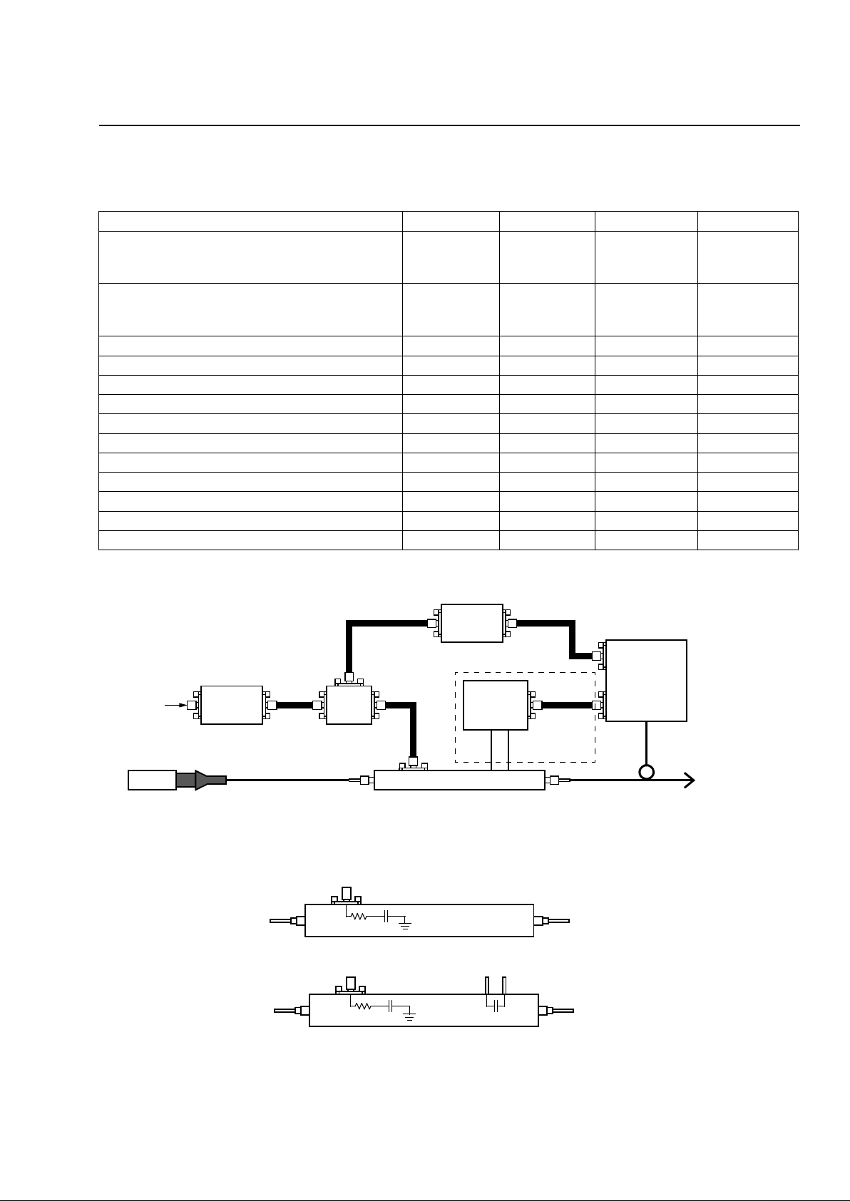
Note: Circuitry in dotted lines is used only with the 2623CSA.
Figure 1. Recommended Operating Circuit Diagram
Figure 2. Equivalent Circuit Diagram
Table 1. Optical/Electrical Characteristics
Parameter Min Typ Max Unit
Operating Wavelength:
C-band
L-band
1525
1565
—
—
1565
1620
nm
nm
Insertion Loss:
2623N, 2623Y, 2623CS
2623CSA
3
3.5
3.7
4.5
5.5
6.5
dB
dB
Extinction Ratio @ dc 20 27 — dB
Extinction Ratio @ RF — 13 — dB
S11 Optical Return Loss — — –35 dB
Bandwidth* 8 10 — GHz
Drive Voltage (Vπ) @ dc 2.8 3.1 4.0 V
Drive Voltage (Vπ) @ 1 GHz 3.5 4.1 5.0 V
Attenuation Voltage @ –19 dB 15 19 22 V
Electrode Impedance — 43 — Ω
S11 Electrical Return Loss (0.13 GHz—5 GHz) — –15 –13 dB
S11 Electrical Return Loss (5 GHz—10 GHz) – –14 –12 dB
S11 Electrical Return Loss (10 GHz—18 GHz) — –8 –6 dB
MODULATOR
DRIVER
BIAS
TEE
dc BIAS
CONTROLLER
PHOTODETECTOR/
PREAMP
dc
ATTENUATION
CONTROLLER
HIGH-
SPEED
DATA
INPUT
PMF
CW-LASER 2623N, 2623Y, 2623CS, 2623CSA
SPLITTER
SEE NOTE.
2623N, 2623Y, 2623CS
43
Ω
0.2 µF
43
Ω
0.2 µF
–10 pF
2623CSA
1-1063 (F)
1-1062 (F)
 Loading...