

Agema AG7448CU-R User Manual

AG-7448CU
Switch
Installation Guide

COMPLIANCES AND SAFETY STATEMENTS
FCC - CLASS A
This equipment has been tested and found to comply with the limits for a Class A digital device, pursuant to
part 15 of the FCC Rules. These limits are designed to provide reasonable protection against harmful
interference when the equipment is operated in a commercial environment. This equipment generates, uses,
and can radiate radio frequency energy and, if not installed and used in accordance with the instruction
manual, may cause harmful interference to radio communications. Operation of this equ ipment in a residential
area is likely to cause harmful interference in which case the user will be required to correct the interference at
his own expense.
You are cautioned that changes or modifications not expressly approved by the party responsible for
compliance could void your authority to operate the equipment.
You may use unshielded twisted-pair (UTP) for RJ-45 connections - Category 3 or better for 10 Mbps
connections, Category 5 or better for 100 Mbps connectio ns, Category 5, 5e, or 6 for 1000 Mbp s conn ections.
For fiber optic connections, you may use 50/125 or 62.5/125 micron multimode fiber or 9/125 micron singlemode fiber.
CE MARK DECLARATION OF CONFORMANCE FOR EMI AND SAFETY (EEC)
This information technology equipment complies with the requirements of the Council Directive 89/336/EEC
on the Approximation of the laws of the Member States relating to Electromagnetic Compatibility and 73/23/
EEC for electrical equipment used within certain voltage limits and the Amendment Directive 93/ 68/EEC. For
the evaluation of the compliance with these Directives, the following standards were applied:
RFI Emission Limit according to EN 55022:2010, Class A
Limit for harmonic current emission according to EN 61000-3-2:2006+A1:2009+A2:2009
Limitation of voltage fluctuation and flicker in low-voltage supply system according to
EN 61000-3-3:2008
Immunity
LVD
Product family standard according to EN 55024:2010
Electrostatic Discharge according to IEC 61000-4-2:2008
Radio-frequency electromagnetic field according to EN 61000-4-3:2006/A1:2007/A2:2010
Electrical fast transient/burst according to EN 61000-4-4:2004/A1:21010
Surge immunity test according to IEC 61000-4-5:2005
Immunity to conducted disturbances, Induced by radio-frequency fields: IEC 61000-4-6:2008
Power frequency magnetic field immunity test according to EN 61000-4-8:2009
Voltage dips, short interruptions and voltage variations immunity test according to
IEC 61000-4-11:2004
EN 60950-1:2006+A11:2009
SAFETY COMPLIANCE
Warning: Fiber Optic Port Safety
When using a fiber optic port, never look at the transmit laser while it is powered on. Also, never look
directly at the fiber TX port and fiber cable ends when they are powered on.
Avertissment: Ports pour fibres optiques - sécurité sur le plan optique
Ne regardez jamais le laser tant qu'il est sous tension. Ne regardez jamais directement le port TX
(Transmission) à fibres optiques et les embouts de câbles à fibres optiques tant qu'ils sont sous tension.
Warnhinweis: Faseroptikanschlüsse - Optische Sicherheit
Niemals ein Übertragungslaser betrachten, während dieses eingeschaltet ist. Niemals direkt auf den
Faser-TX-Anschluß und auf die Faserkabelenden schauen, während diese eingeschaltet sind.
- 2 -

CONTENTS
1INTRODUCTION 4
Overview 4
Features 4
Front View 5
Rear View 5
LED Identification 6
Technical Specifications 8
System Requirements 9
Data Center Deployment 9
Power Supply Modules 10
Fan Tray Module 10
2INSTALLING THE SWITCH 11
Equipment Checklist 11
Package Contents 11
Mounting 12
Rack Mounting 12
Horizontal Surface Mounting 14
Installing an Optional SFP+/QSFP Transceiver 15
Connecting to the Console Port 16
Connecting to a Power Source 17
3MAKING NETWORK CONNECTIONS 18
Twisted-Pair Connections 18
Cabling Guidelines 18
Connecting to the Management Port 18
Fiber optic Connections 19
Ethernet Cabling 19
4SUPPORT AND CONTACT INFORMATION 20
Limited and Support Warranty 20
Contact and Return Information 20
- 3 -

1
INTRODUCTION
OVERVIEW
The AG-7448CU is a bandwidth rich switch. The device has forty-eight 10GbE SFP+ ports
and four 40GbE QSFP slots. In addition to the rich bandwidth, the AG-7448CU provides
comprehensive switch hardware capability to support Cumulus layer 2 and layer 3 features.
FCoE and MPLS are also supported on the AG-7448CU Designed for high-speed
throughput and featuring leading edge software, this switch carries on Agema's tradition of
producing affordable, high performance workgroup layer 3 stackable switches.
FEATURES
The following lists the key main features of the AG-7448CU switch:
640Gbps switching bandwidth (1280Gbps duplex)
Support Jumbo Frame up to 12Kbyte
Automatic address learning function to build the packet-forwarding information table.
The table contains up to 128K MAC addresses
Store-and-Forward transmission to remove bad packets from the network
Alternate Store-Forward (ASF) mode - Cut-through is available to minimize the latency
Power supply LED / Stack ID / FAN status LED indication
Extensive system LED and per port LEDs
External power supply
Standard 1U chassis high
17" rack mountable
Memory Management:
8 MB of packet buffer memory
Explicit Congestion Notification (ECN)
Weighted Random Early Detection (WRED)
- 4 -
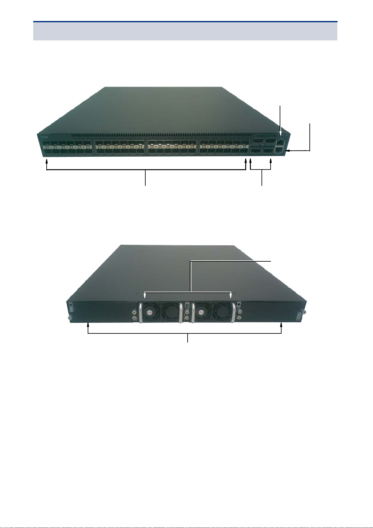
FRONT VIEW
SFP+ port x 48 QSFP port x 4
Management port x 1
Ethernet port x 1
Redundant PSU x 2
System fan x 4
Figure 1: Front View
CHAPTER 1 | Introduction
Overview
REAR VIEW
Figure 2: Rear View
- 5 -
CHAPTER 1 | Introduction
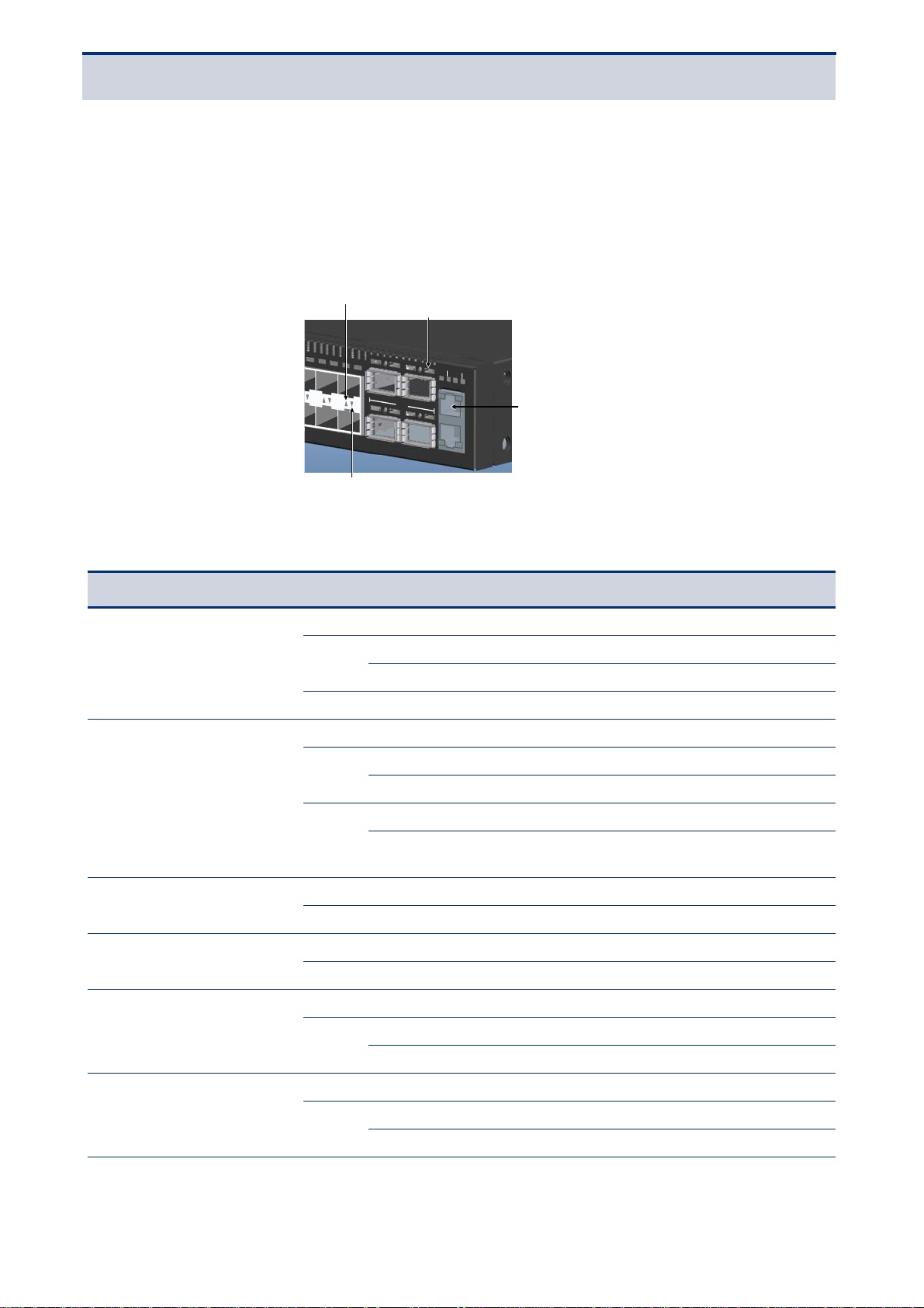
Upper SFP+ Port LED
Lower SFP+ Port LED
QSFP+ LED
Management Port LED
Front
Overview
LED IDENTIFICATION
This section provides an overview of the front and rear LEDs.
Front LEDs
Figure 3: Front LED Identification
Master
PSU
SYS FAN
52 60
QSFP+
2
4644
48 56
RS-232
Enthernet
ACTLNK
Table 1: Front LED Identification Fi elds
LED Color Status Description
Green Solid Both power suppliers presented and operating normally
Power
System
Master
Fan status
40G QSFP slot (1x LED per
port)
Amber
N/A OFF Power disconnected
N/A OFF No power
Green
Red
N/A OFF Unit is in slave mode
Green Solid Unit is in master mode
Green Solid Fan operating normally
Amber Solid Fan failure
N/A OFF No link
Green
Solid POST in progre ss
Blinking One power supply has failed
Blinking Booting up or running diagnostics
Solid Normal operation
Solid Critical system error
Blinking
Non-critical system error, for example redundant power
supply failure
Solid A valid link
Blinking Packet transmission or reception in progress
10G SFP+ slot (1x LED per
port)
N/A OFF No link
Solid A valid link
Green
Blinking Packet transmission or reception in progress
- 6 -
 Loading...