

AGD SYSTEMS MC 133 User Manual
RFbeam Microwave GmbH
© RFbeam Microwave GmbH www.rfbeam.ch
Parameter
Conditions / Notes
Symbol
Min
Typ
Max
Unit
Operating conditions
Supply voltage
V
cc
3.15
3.3
6.0
V
Supply current
Module enabled
I
cc1
40
60
80
mA
RF-Part disabled
I
cc2
5 10
mA
VCO input voltage
U
vco
0
5.5
V
VCO pin resistance
Internal pulldown 100k
R
vco
100k
Operating temperature
T
op
-20
+70
°C
Storage temperature
T
st
-40
+85
°C
Power down/Enable
RF power down
Input tied high with pullup 100k
V
IH1
2.7
Vcc+ 0.3
V
RF enable
V
IL1
-0.2
0.7
V
Minimum enable time
RF-part fully functional
ton
5
s
Maximum hold time
LP capacitor charge error < 10%
t
off
2 ms
Transmitter
Transmitter frequency
U
VCO
= 3.0V, T
amb
= 25°C
f
TX
24.120
24.125
24.130
GHz
Frequency drift vs temp.
Vcc=3.3V, -20°C .. +70°C
fTX
-0.27
MHz/°C
Frequency tuning range (VCO)
U
VCO
= 1V .. 5V
f
vco
35
50
70
MHz
VCO sensitivity
S
vco
12.5
MHz/V
VCO Modulation Bandwidth
f=1MHz
B
VCO
200
kHz
Output power
EIRP
P
TX
+13
+16
+20
dBm
Output power deviation
Full VCO tuning range
PTX
+/- 2
dBm
Spurious emission
According to ETSI 300 440
P
spur
-30
dBm
Receiver
Antenna gain
FTX=24.125GHz
G
Ant
15
dBi
LNA gain
FRX=24.125GHz
G
LNA
9 dBMixer Conversion loss
fIF =500Hz
D
mixer
-2.0
dB
Receiver sensitivity
fIF =500Hz, B=1kHz, S/N=6dB
P
RX
-114
dBm
Overall sensitivity
fIF =500Hz, B=1kHz, S/N=6dB
D
system
-130
dBc
Datasheet
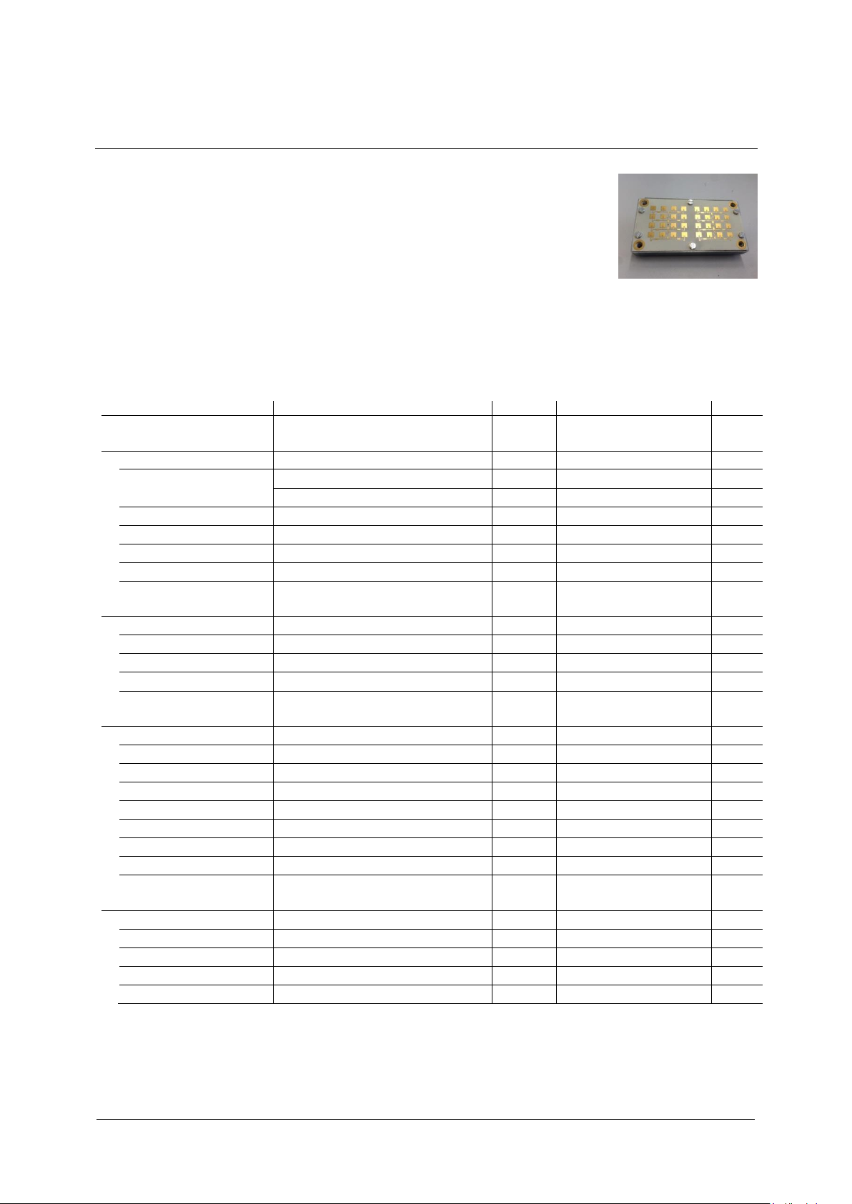
AGD-T7813-125 Issue ‘1’ MC-133
Introduction
This document describes the AGD-T7813 modules Issue ‚1’.
This module has the following features:
Improved Ceramics Material (Temex E2036)
RF-Transistor with higher gain
Adjusted PCB Layout with tighter coupling for Resonator (lower loss)
Electrical Specification
Page 1/5
RFbeam Microwave GmbH
Datasheet
© RFbeam Microwave GmbH www.rfbeam.ch
Parameter
Conditions / Notes
Symbol
Min
Typ
Max
Unit
IF output
IF output impedance
R
IF
100
IF Amplifier gain
G
IF
30
dB
I/Q amplitude balance
fIF =500Hz, UIF=100mVpp
U
IF
3
dB
I/Q phase shift
fIF =500Hz, UIF=100mVpp
70
90
110
°
IF frequency range
-3dB Bandwidth
f
IF_AC
20
500k
Hz
IF noise voltage
fIF =500Hz
U
IFnoise
1.0
3.2
7.9
V/Hz
fIF =500Hz
U
IFnoise
-120
-110
-102
dBV/Hz
IF output offset voltage
Vcc = 3.3V
U
os_AC
1.0
1.5
2.0
V
Supply rejection
Rejection supply pins to IF outputs, 1kHz
D
supply
26
dB
Antenna
Horizontal -3dB beamwidth
E-Plane
W 28
30
32
°
Vertical -3dB beamwidth
H-Plane
W
28
30
32
°
Horiz. sidelobe suppression
D
-20
-25
dB
Vert. sidelobe suppression
D
-16
-20
dB
Body
Outline Dimensions
connector left unconnected
35*65*17
mm3 Weight
62
g
Connector
8
pins
AGD-T7813-125 Issue ‘1’ MC-133
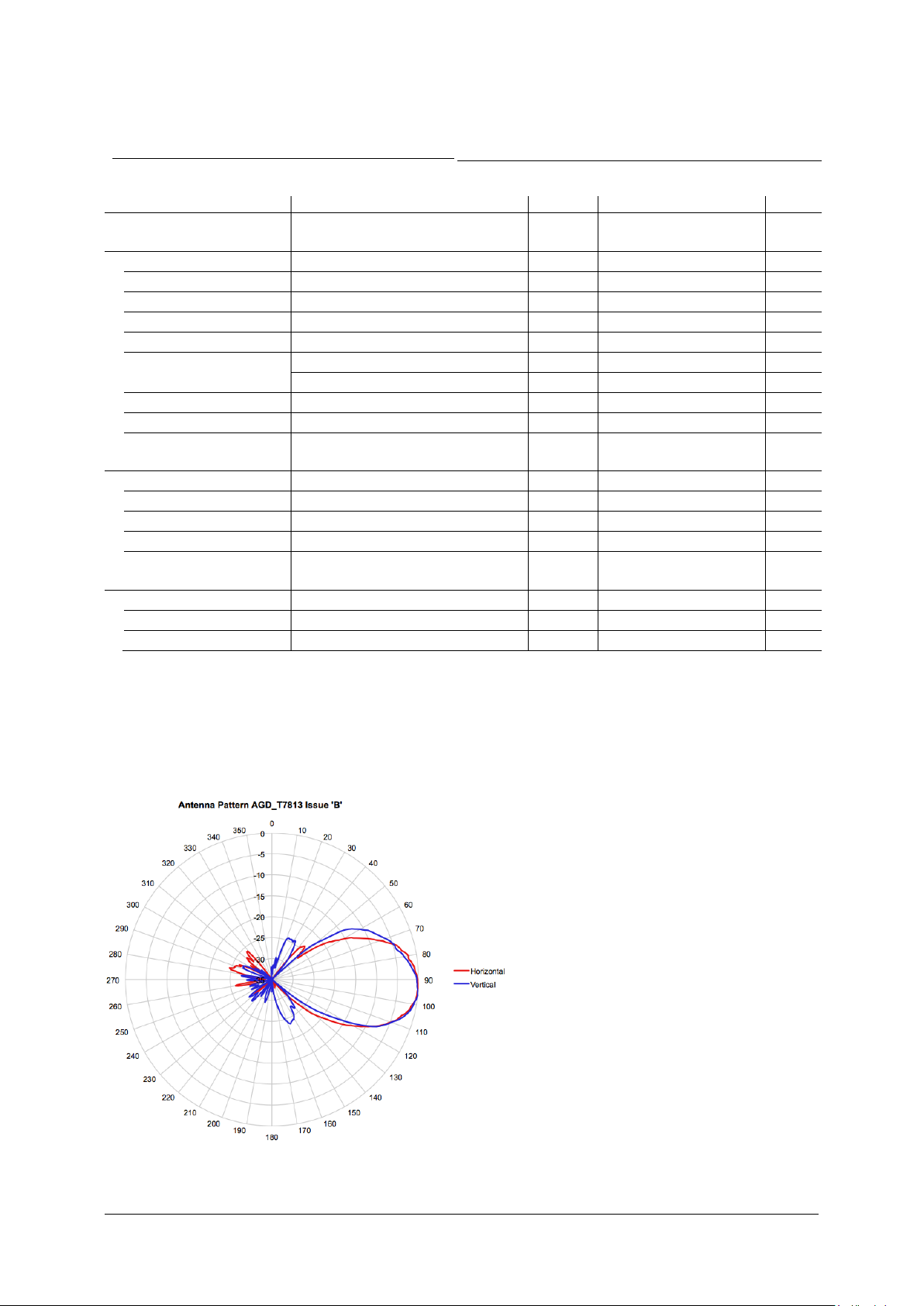
Antenna Pattern
Typical Antenna Pattern for one antenna (RX- or TX-side). Measured at 24.200GHz:
Page 2/5
 Loading...