

AGD SYSTEMS AGD315 207 User Manual
AGD315-205 and AGD315-207
RADAR USERS MANUAL
1 INTRODUCTION
These instructions detail the use and operation
of the AGD315-205 and -207 radars. This
radar has been specifically designed for the
accurate measurement of the speed and range
of passing vehicles when mounted at the side
of the road for enforcement purposes. The
radar is designed to work in conjunction with
an AGD340 radar plus a host, photographic
based, enforcement system. The host system
may be mobile or fixed location in nature.
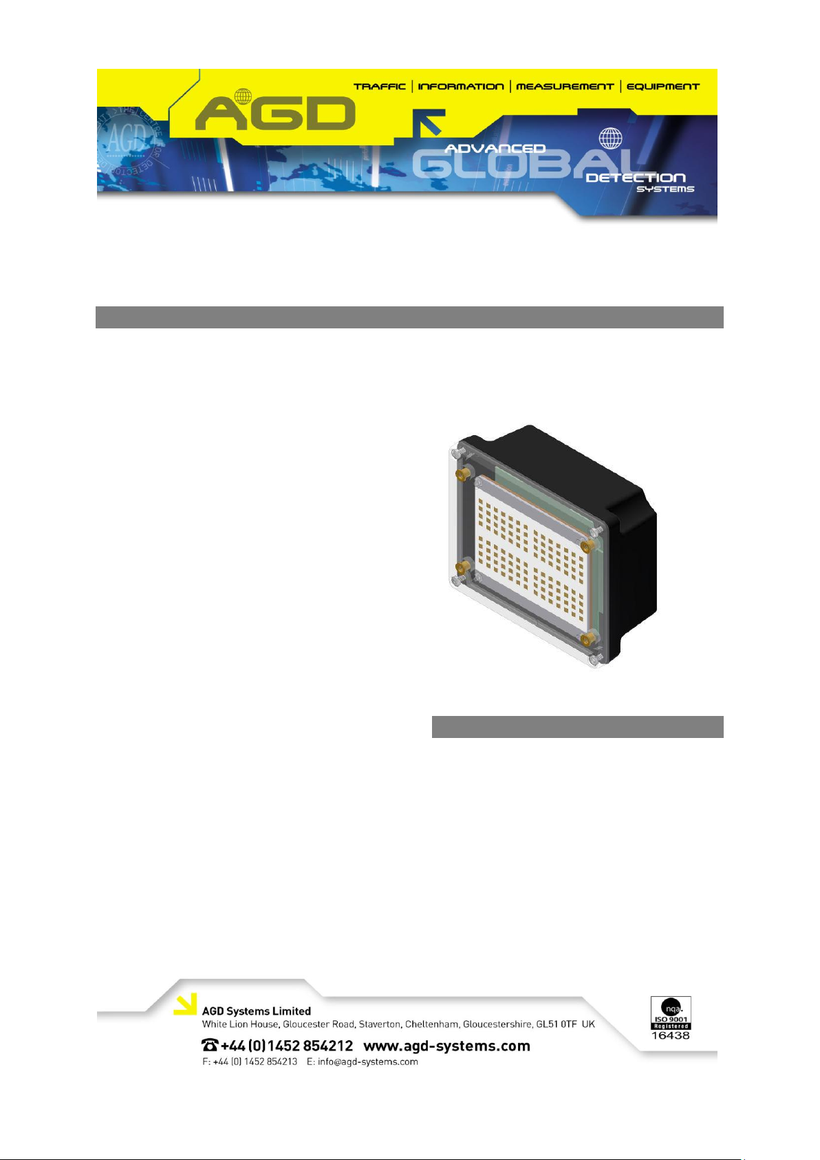
The radar is supplied in a black plastic
enclosure which incorporates all the radar
circuitry and processing circuitry to perform the
speed and range measurement. The
connection to the radar is via a 1 metre cable
with multi-pin connector, and mounting is
provided by fixings on the housing.
The AGD315-205 is a 24.2GHz frequency
modulated continuous wave (FMCW) radar
whereas the AGD315-207 is a 24.125GHz
(24.075GHz-24.175GHz) radar which are
capable of measuring range and speed. The
radar’s integral planar antenna forms a narrow
beam which is sited at a predetermined angle
across the road. When vehicles pass through
the beam the radar accurately measures the
speed and range at a frame rate of 40
readings per second via an advanced digitising
and tracking technique to a resolution of
approximately 1 mph and 2 metres.
Details of each vehicle speed measurement
are passed to the host system via a high
speed serial communications interface.
Changes or modifications to this equipment,
not expressly approved by AGD Systems Ltd,
may void the user’s authority to operate this
equipment
1 INTRODUCTION
2 DOCUMENT REVISION
3 FMCW OVERVIEW
4 SPECIFICATIONS
5 SYSTEM HARDWARE OVERVIEW
6 MESSAGE FORMATS
7 RADAR USAGE
8 CABLE CONNECTIONS
9 TEST & CALIBRATION
Contents
© AGD Systems Ltd 2010. All rights reserved., the information contained in this document is the property of AGD Systems Ltd., and is supplied
without liability for errors or omissions. AGD315 User ManualPage 1 of 12
,
Issue
Amendment Details
Date of Issue
By
1
Initial Draft
23/12/2009
NK
2
DCR3006 – added section relating to test and
calibration procedures. Figures and Tables
identified using auto-numbered captions.
14/06/2010
SCH
2 DOCUMENT REVISION
3 FMCW OVERVIEW
3.1 Basic Operating Principles of FMCW Radar
In an FMCW radar such as the AGD315-205/207, the following basic operating principles are applied:
The transmit signal is frequency modulated, normally by a linear modulation (a chirp)
The modulation of the received signal is compared to the modulation of the transmitted signal to
determine time delay and therefore range
velocity is determined by range differentiation or Doppler processing
Consider a signal transmitted from the radar at time t=0 and with frequency f
strikes a target, the signal will be reflected back and received by the radar at a time t=t
the time of flight of the reflected signal. the transmit frequency will have increased to a new frequency
f
delayed
, where f
is given by the chirp rate and amplitude.
delayed
Hence at any instance in time after t
, there is a difference in frequency between the transmitted
delayed
and received frequencies. This frequency difference is proportional to the time of flight for the
received signal, and since the radar signal travels at the speed of light (a constant), the time of flight is
also proportional to the range of the target which reflected the radar signal.
In an FMCW system, the transmit and receive signals are compared using an RF Mixer. The mixer is
driven by the transmit and receive signals, and the mixer output is the difference between the two
input signals. The output signal is referred to as the intermediate frequency (IF).
If the IF is sampled into an analogue to digital converter (ADC) at fixed time intervals during a single
excursion of the frequency modulation (one period of the chirp) and the resultant digital signal is
viewed in the frequency domain, a number of different frequencies will be seen, where each frequency
corresponds to a target at a particular range.
If data from a number of successive chirps is gathered and processed, speed and range for individual
targets can be determined.
. When this signal
start
delayed
. During
© AGD Systems Ltd 2010. All rights reserved., the information contained in this document is the property of AGD Systems Ltd., and is supplied
without liability for errors or omissions. AGD315 User Manual Page 2 of 12
Radar General
Items
Specification
Notes
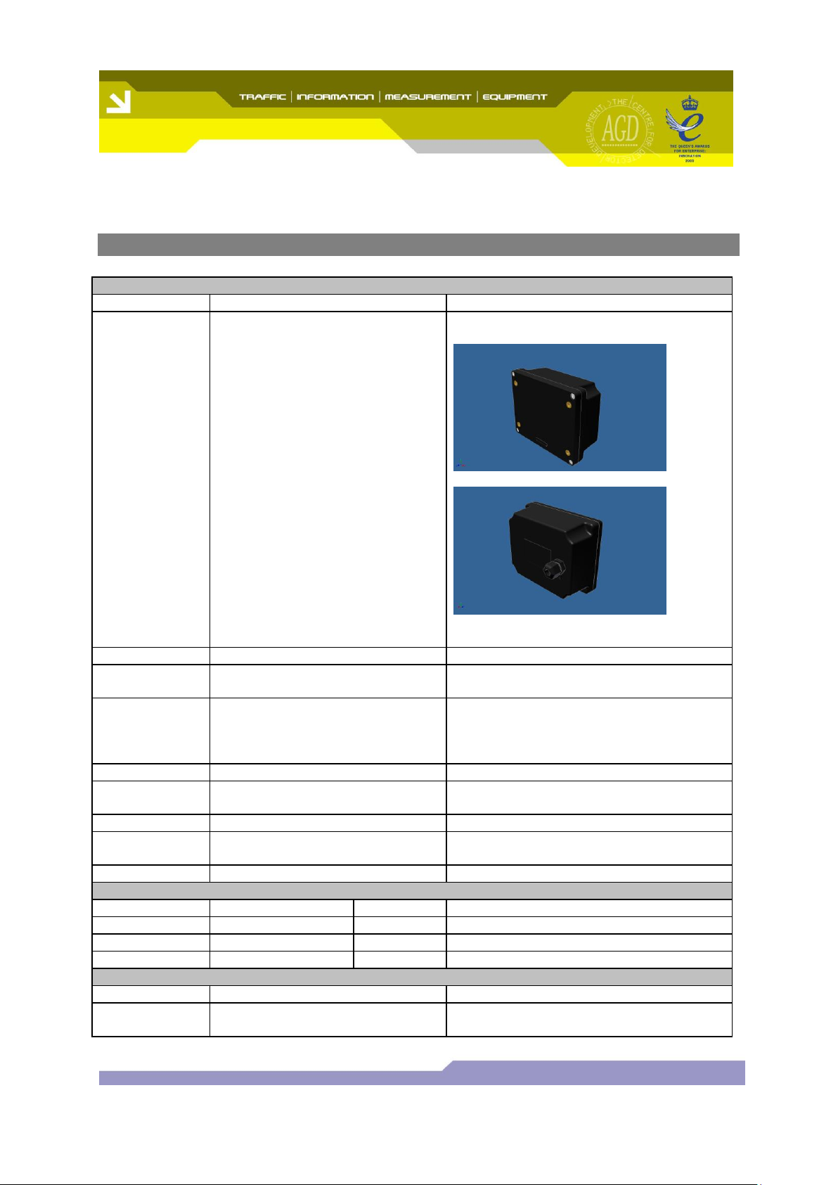
Housing
Black UV stabilised polycarbonate
Fine spark finish
Radar Weight
0.80 Kg
Including 1 metre lead and connector
External
Dimensions
160mm(W) x 130mm(H) x
60mm(D)
Mounting
Fixings
4 x M4 threaded inserts
M16 cable gland
Sealing
IP66
Radar
Connection
9 pin Bulgin Bucanneer (male)
attached to end of 1 metre lead
Bulgin PX0728/P
See section 9 for more information
Radar Labelling
Manufacturer’s Label
LED
Red status indicator LED
Blue ‘Bluetooth’ indicator LED
Radar Power Connection
Parameter
Specified
Tolerance
Notes
Supply Voltage
24V dc
9-30V
Current
263mA
10%
At 12Vdc
Radar Data Connection
Parameter
Specified
Notes
4 wire RS 422
See extra notes on data connection and
BAUD command.
4 SPECIFICATIONS
,
© AGD Systems Ltd 2010. All rights reserved., the information contained in this document is the property of AGD Systems Ltd., and is supplied
without liability for errors or omissions. AGD315 User Manual Page 3 of 12
Environmental Performance
Test
Severity
Specification
Cold
(-20 C Operational)
IEC 68-2-1 Test Ab
Dry Heat
+60 C Operational
IEC 68-2-2 Test Bb
Damp Heat
Cyclic 48Hrs 25 C to 40 C 95%RH
IEC 68-2-30 Test Db
Free Fall
Each top rear corner & each top
rear face. 1000mm free fall to
concrete.
IEC 68-2-32 Test Ed
Drop and
Topple
All faces & corners 100mm drop
IEC 68-2-31 Test Ec
Shock
4000m/S2, 2mS Duration
IEC 68-2-27 Test Ea
Random
Vibration
0.02g2/ Hz (10-50Hz)
0.01g2/ Hz (50-150Hz)
0.002g2/ Hz (150-500Hz)
Overall RMS 1.58g 3Hrs on X,Y,Z
axes
IEC 68-2-34 Test Fd
Sinusoidal
Vibration
5-7Hz 1.5mm
7-35Hz 10m/S2
IEC 68-2-6 Test Fc
Bump
1000 in X,Y,Z axes 100m/S2,16mS
IEC 68-2-29 TestEb
Immersion
Preconditioned to +30 C over
ambient before 12Hrs Immersion.
IEC 68-2-18 Test R
Radar Transceiver
Component
Specification
Notes
Antenna
Planar patch array
Transmitter
Quarter wave resonator
Receiver
Homodyne I Q down converter
Radome
Black UV stabilised polycarbonate
Radar Transmission
Parameter
Specified
Notes
Radar Centre
Frequency
24.200 GHz UK/EU/AS/NZS
24.125GHz USA
Modulation
Bandwidth
80MHz
Operating
Frequency Band
24.150 - 24.250GHz (UK/EU/AS/NZS)
24.075 – 24.175GHz (USAVersion)
Modulation bandwidth of ~80MHz plus
temperature stability guard bands (+/10MHz)
Fundamental
Frequency Power
<20dBm EIRP
Fundamental
Frequency Field
Strength
<1000mV/m
@3m
Frequency
Temperature
Stability
Typically < 1 MHz/ C
Uncompensated
Polarisation
Plane polarised with E-Field vertical
Horizontal
Beamwidth
7 degrees
,
© AGD Systems Ltd 2010. All rights reserved., the information contained in this document is the property of AGD Systems Ltd., and is supplied
without liability for errors or omissions. AGD315 User Manual Page 4 of 12
 Loading...