

AGD SYSTEMS 350101 Users Manual
350
VEHICLE DETECTION
Enforcement Radar Traffic Detector
PRODUCT MANUAL
CERTIFIED
ISO 9001
Registered
Quality
Management
ISO 14001
Registered
Environmental
Management
015
015
©AGD Systems Limited 2015 Doc. Ref. 350 PM ISS 2

TABLE OF CONTENTS
INTRODUCTION
Product & technology 3
Key features 3
Typical applications 4
Product overview 5
INSTALLATION
Radar mounting 6
Radar Installation - Red Light Enforcement (receding flow) 7-8
Radar Installation - Red Light Enforcement (avancing flow) 9-10
Radar mounting 11
Selecting a suitable site 11
Radar Speed Accuracy 11
Radar Range Accuracy 11
Radar Angular Accuracy 11
Radar Angle and Range Modes 11
SYSTEM HARDWARE OVERVIEW
System hardware overview 12
RS422 serial interface 13
Ethernet Interface 14
Power supply 15
Power up Sequence 15
Power Supply Tolerance 15
Mating Connector Pin Out Connections 15
RADAR CHARACTERISTICS
General 16
Frequency Variants 17
Antenna Plots 18
RADAR COMMANDS
Radar Command Overview 19
Radar Command list 20-21
MESSAGE FORMATS
Detect Message 22-23
Event Trigger Point Message 24-25
Tracked Target Message 26-27
Heartbeat Message 28
TECHNICAL SPECIFICATIONS
Product specification 29
MANUFACTURING TEST PROCESS
Hyperion Test Equipment 30
END OF LIFE – DISPOSAL INSTRUCTIONS (EOL) 31
IMPORTANT SAFETY INFORMATION
Safety precautions 32
Low power non-ionising radio transmission and safety 33
DISCLAIMER 36
Warranty 36
2
INTRODUCTION
PRODUCT & TECHNOLOGY
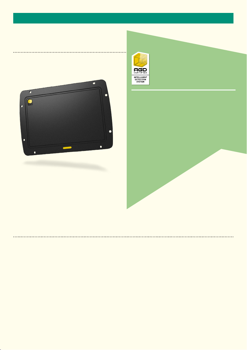
350
The 350 is specifically designed for O.E.M integration
into photo enforcement systems to measure the
position, speed and range of passing vehicles.
Operating in the K-band at 24GHz, the radar offers
market leading performance for demanding
applications such as red light (&speed) and yellow box
violations at signalised intersections.
Positioned in front of (or optionally behind) an
intersection stop line, the 350 will track up to
thirty two targets simultaneously and allows
the setting of two precise trigger
points for data output to the
host system when a
violation occurs.
KEY FEATURES
• Radar reports speed, range and positional data to each event
• Tracks up to 32 simultaneous targets
• Speed measurement from 10kph - 250kph
• Target range 4m - 85m
• 40º field of view
• Suitable for advancing or receding traffic flow
• Dual user selectable virtual trigger points
• High speed RS422 serial communications
• Optional Ethernet interface
• Continuous radar self-check features
• Self calibrating bandwidth control
3
INTRODUCTION
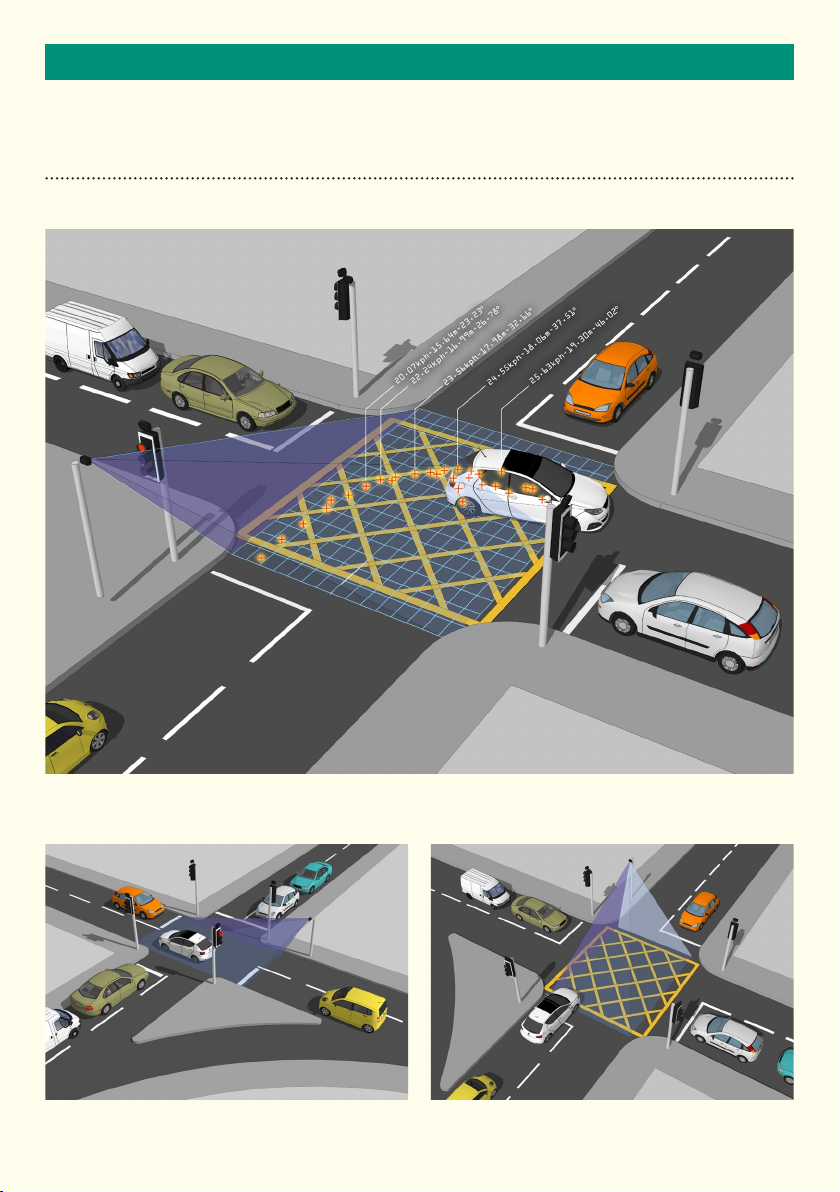
TYPICAL APPLICATIONS
Vehicle speed, distance and angle is captured through the detected zone
Red light violation Yellow box violation
4
INTRODUCTION
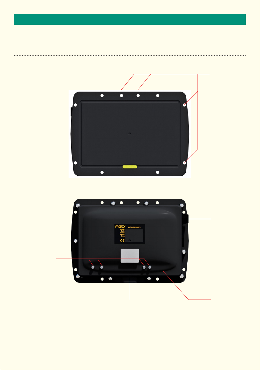
PRODUCT OVERVIEW
Flange mounting
points
Multi-function LEDs
Tripod mounting point
or
mounting bracket fixing
5
Multi-pin
mating
connector
RJ45 Ethernet
connector

INSTALLATION
RADAR MOUNTING
The radar mounting features and dimensions are shown below.
30,0035,00
104,00
Ø 5,70 -14,97 DE EP
1/4-20 UNC - 1B
M4x0.7 - 6H
35,00
48,0048,00
12,25
22,25
26,25
44
6
INSTALLATION
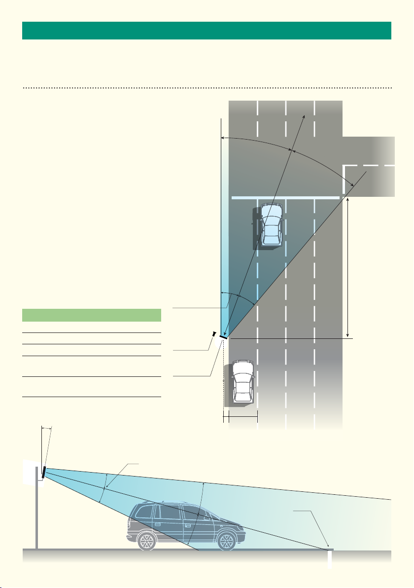
RADAR INSTALLATION - RED LIGHT ENFORCEMENT (RECEDING FLOW)
The nature of the design of the radar lends itself to
versatility in its mounting on the roadway. There are
however, factors to be considered when siting the
radar to ensure optimum performance is achieved.
The radar should be installed at an angle of
approximately 20º from the pavement line and sited
toward the centre of the junction area. The area to
be enforced should be within the ‘D1’ range of the
radar (85 metres max). Mounting height should
be approximately 3 metres from ground level.
Offset (setback) should be approximately 2 metres.
Declination angle of the radar head should be
approximately 10º.
Care should be taken to ensure that the area of
interest is covered by the 40º field of view, this can
be affected by mounting height, correct mounting
angle to the road, correct declination
angle and the radar offset.
Horizontal
field of view
350 Radar Installation Approximation
D1 - Maximum range at centre of radar bore (85m)
D2 - approximate distance from the stopline (20m)
Offset - approximate setback from lane 1 (2m)
Horizontal field of view - approximately
centre bore of radar
Vertical field of view - approximately
bore of radar
±20º from
±10º from centre
Host
Enforcement
350 Radar
20º
Lane 1
Lane 2 Lane 3 Lane 4
20º
D1
D2
10º
Declination angle
(Downward toward
pavement)
3.5m
Offset 2m
Vertical field of view
Approximate
stopline location
7
INSTALLATION
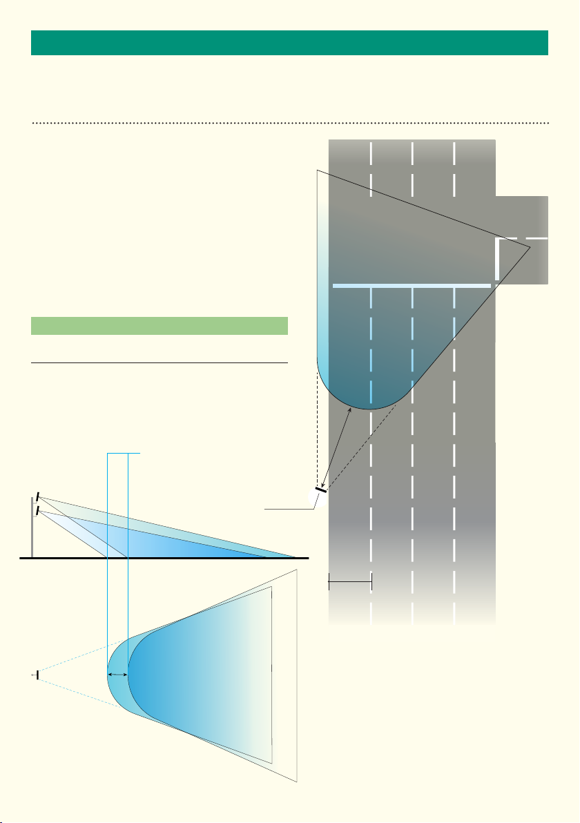
RADAR INSTALLATION - RED LIGHT ENFORCEMENT (RECEDING FLOW)
This diagram shows the potential beam coverage of the
350 Radar being used to monitor an intersection for red
light enforcement. The ‘D4’ distance is an important
consideration when adjusting mounting parameters of
the radar.
Adjusting mounting height, offset and mounting angle
will all have the effect of increasing or decreasing the
‘D4’ value. The value is defined as the initial point of
radar coverage on the surface of the roadway. See
diagram below.
350 Radar Installation Analysis (beam coverage)
D4 - This distance is approximately four metres based on suggested
parameters but is variable.
20º
20º
Initial point of radar coverage
on road shifts upon adjustment
of radar height.
Shift
350 Radar
8
D4
Lane 2 Lane 3 Lane 4
Lane 1
3.5m
INSTALLATION
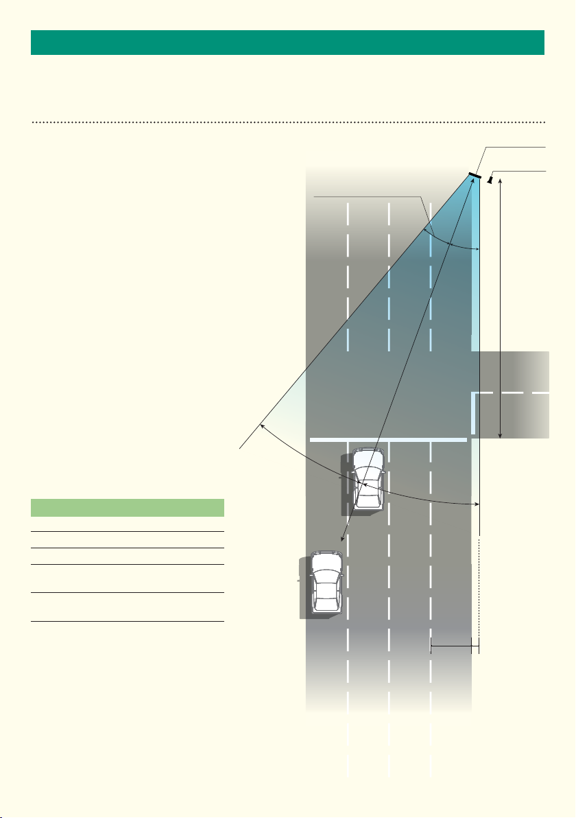
RADAR INSTALLATION - RED LIGHT ENFORCEMENT (ADVANCING FLOW)
The nature of the design of the radar
lends itself to versatility in its mounting
on the roadway. There are however,
factors to be considered when siting the
radar to ensure optimum performance is
achieved.
The radar should be installed at an angle
of approximately 20º from the pavement
line and sited toward the centre of the
junction area. The area to be enforced
should be within the ‘D1’ range of the
radar (85 metres max). Mounting height
should be approximately 3 metres from
ground level. Offset (setback) should
be approximately 2 metres. Declination
angle of the radar head should be
approximately 10º.
Care should be taken to ensure that the
area of interest is covered by the 40º field
of view, this can be affected by mounting
height, correct mounting angle to the
road, correct declination
angle and the radar offset.
350 Radar Installation Approximation
D1 - Maximum range at centre of radar bore (85m)
D2 - approximate distance from the stopline (20m)
Offset - approximate setback from lane 1 (2m)
Horizontal field of view - approximately
centre bore of radar
Vertical field of view - approximately
bore of radar
±20º from
±10º from centre
Horizontal
field of view
Lane 1
20º
Lane 2 Lane 3 Lane 4
D1
20º
350 Radar
Host
Enforcement
D2
3.5m
Offset 2m
9
INSTALLATION
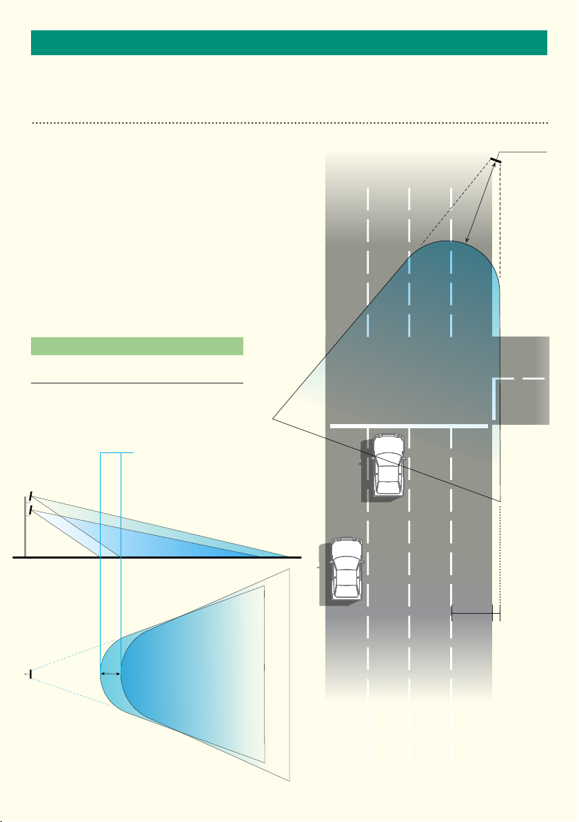
RADAR INSTALLATION - RED LIGHT ENFORCEMENT (ADVANCING FLOW)
This diagram shows the potential beam
coverage of the 350 Radar being used
to monitor an intersection for red light
enforcement. The ‘D4’ distance is an
important consideration when adjusting
mounting parameters of the radar.
Adjusting mounting height, offset and
mounting angle will all have the effect of
increasing or decreasing the ‘D4’ value. The
value is defined as the initial point of radar
coverage on the surface of the roadway. See
diagram below.
350 Radar Installation Analysis (beam
coverage)
D4 - This distance is approximately four metres based on
parameters but is variable.
suggested
Initial point of radar coverage
on road shifts upon adjustment
of radar height.
350 Radar
Lane 1D4Lane 2 Lane 3 Lane 4
Shift
3.5m
Offset 2m
10

INSTALLATION
RADAR MOUNTING
As highlighted on the previous page(s). There is a certain amount of flexibility in the position of where the
RADAR is mounted. The offset, height, distance from stop line, even orientation in relation to the stop line can
be altered, however when selecting a mounting position, all parameters should be reviewed to ensure that
sufficient RADAR beam coverage of the area of interest, can be achieved at the chosen mounting location.
Selecting a Suitable Site
When choosing to deploy the radar at a location, the following is a non-exhaustive list of considerations which
should be taken into account.
• Does the proposed mounting position give sufficient beam coverage to ‘view’ the enforceable area ?
• Are there any large reflecting surfaces directly in front or behind the RADAR mounting position ?
Radar Speed Accuracy
Simulated target up to 262km/hr ±…….Km/hr
Real target typical accuracy ±…….Km/hr
Radar speed resolution readout 0.1 Km/hr
Radar Range Accuracy
Simulated range up to 70m ±………m
Real target range accuracy ±2m for a range up to 70m
Range readout resolution 0.1m
Radar Angular Accuracy
Simulated angle ±…….º
Real target angular accuracy ±…….º
Angular readout resolution 0.1 º
Radar Angle and Range Modes
The radar has two modes when reporting range and angle. This can be set to a distance based range and
angular approach of the target vehicle, or alternatively, the position of the vehicle can be expressed as an
‘X, Y’ co-ordinate (polar or cartesian).
11
 Loading...