

AGD SYSTEMS 343501 User Manual
AGD 343
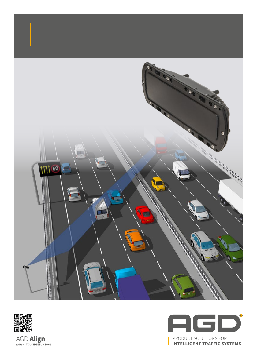
HIGHWAYS MONITORING RADAR
AGD 343
HIGHWAYS MONITORING RADAR
PRODUCT MANUAL
© AGD Systems Limited 2019 Doc. Ref 343 PM ISS1
✓

Table of Contents
INTRODUCTION 2
Product and Technology 2
Key Features 2
Typical Applications 2
Product overview image 2
Installation 3
Installation Information 3
Mounting Location 3
Mounting Location Considerations 3
Physical Installation 4
343 Mounting Bracket Kit 4
Step 1 – Mount bracket to the pole 4
Step 2 – Mount bracket to the radar 4
Step 3 – Mount radar to the pole 5
Electrical Installation 6
Connections 6
343 Power/RS422 Cable Assembly 6
AGD 343
HIGHWAYS MONITORING RADAR
safer, greener, more eicient
2
Introduction
PRODUCT & TECHNOLOGY
AGD 343
HIGHWAYS MONITORING RADAR
The AGD 343 Highways Monitoring Radar is an easy-tointegrate traic flow monitoring solution that provides
real-time data on multi-lane highways. Designed for traic
profiling and incident detection, the 343 dramatically
enhances highways safety, capability and eiciency.
AGD’s 343 employs proven enforcement-grade radar &
measurement techniques to quantify speed, range and
length of passing vehicles. Detailed traic information
- such as, ‘is traic free-moving, slowing or starting-toqueue?’ - is available in all weather conditions to inform
control rooms and allow instant decision making.
AGD radar can replace intrusive high-maintenance loops,
mounting on existing roadside poles or gantries where
it ‘looks’ across the road at 30 degrees. The additional
capability to operate at a ≥ 2-metre oset, while
maintaining a 6-metre plus mounting height, ensures
reliable operation in managed motorway scenarios and
ALR (All Lanes Running) schemes. The 343 has been
designed to cope with the many diiculties
facing international road network installations.
KEY FEATURES
• Flow monitoring solution for multi-lane real-time data
• Traffic Profiling and Incident Detection
• Ten lane highway capability
• Enforcement grade radar & techniques
• Identifies, tracks & measures speed, length, lane/direction of individual targets
• Multi-level incident detection mode
• Non-intrusive loop replacement
• Mounts on existing infrastructure
• Simple to install, setup and configure using AGD Align
3
Introduction
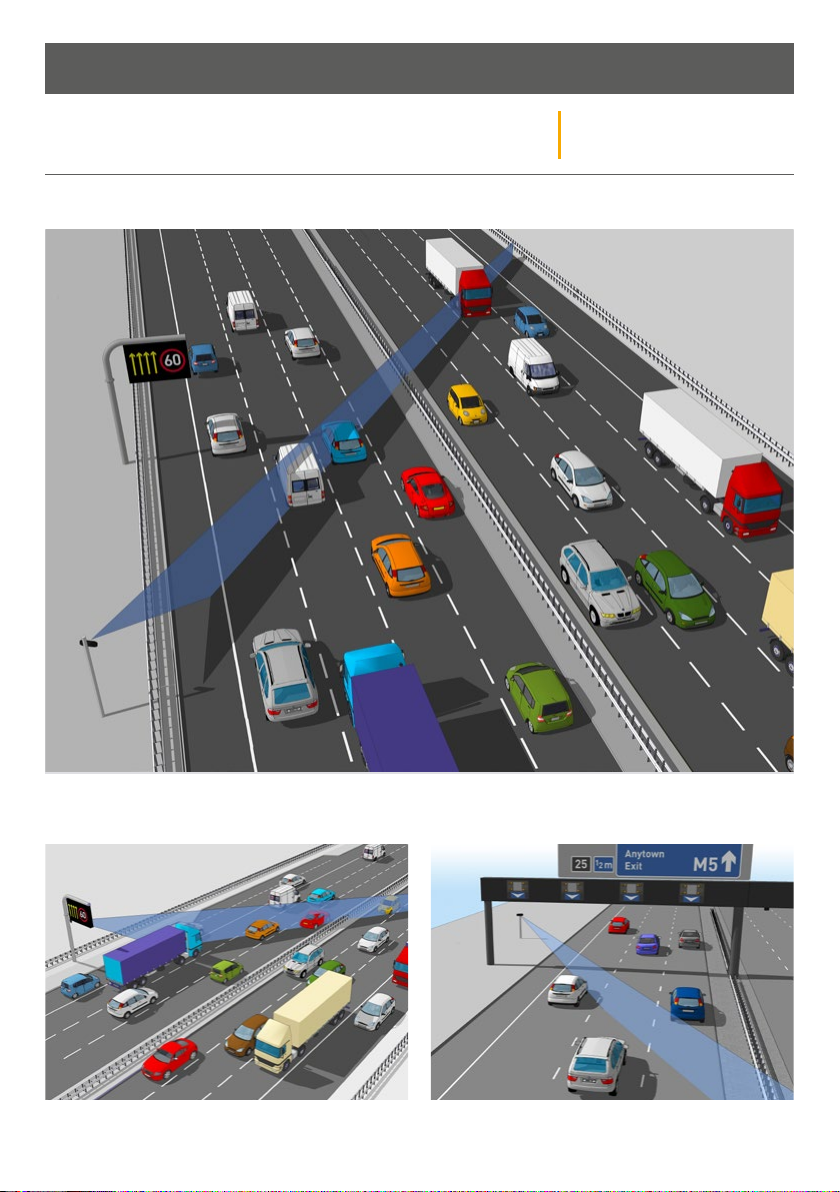
TYPICAL APPLICATIONS
Multi-Lane Highways Monitoring Radar
AGD 343
HIGHWAYS MONITORING RADAR
Caption Caption
4
Introduction
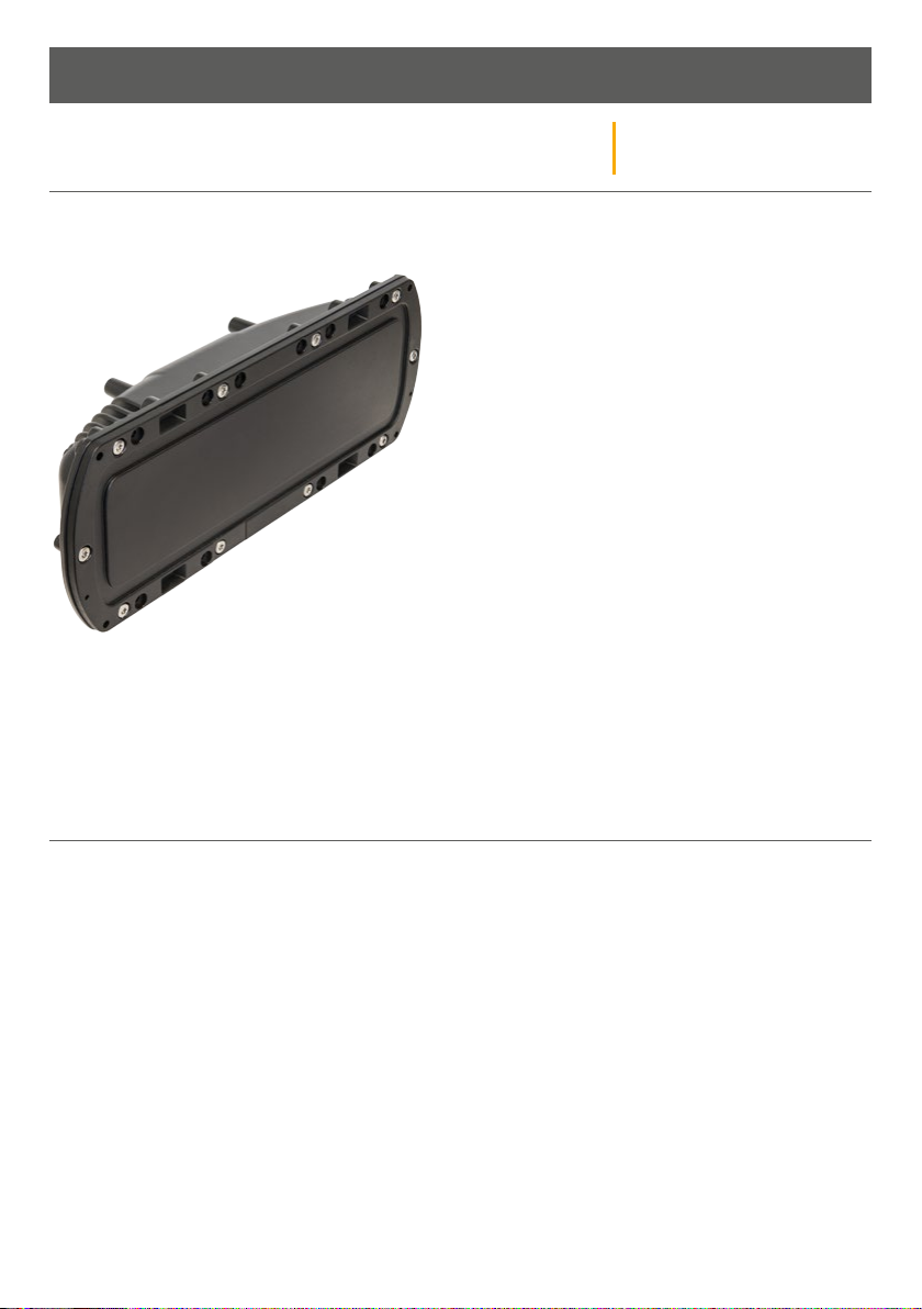
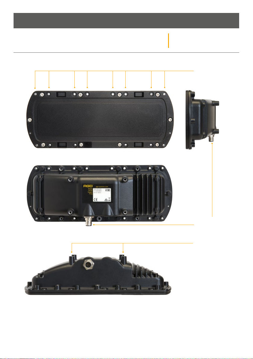
PRODUCT OVERVIEW
AGD 343
HIGHWAYS MONITORING RADAR
Flange Mounting
Points
safer, greener, more eicient
5
Power/RS422 Cable
Connector Port
X4 Fixing Points
Installation
AGD 343
INSTALLATION INFORMATION
The radar is designed to be mounted to various structures such as a dedicated column, gantry or sign.
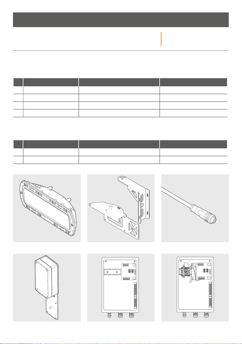
To install the radar, the following parts will be required:
No. Part No Description Notes
1 343-500-000 AGD 343 Highways Monitoring Radar
2 MS-246 343 Mounting Bracket Kit
3 CA-310 343 Power/RS422 Cable Assembly
4 MK343-05 Camera Setup Tool (this is removed upon setup)
To provide power and communication interfaces the following parts will assist in detector integration:
No. Part No Description Notes
5 MK343-01 343 Interface Enclosure
6 MK343-03 343 Interface Enclosure (c/w 24Vdc PSU)
HIGHWAYS MONITORING RADAR
1
4
2
5
6
3
6
Installation
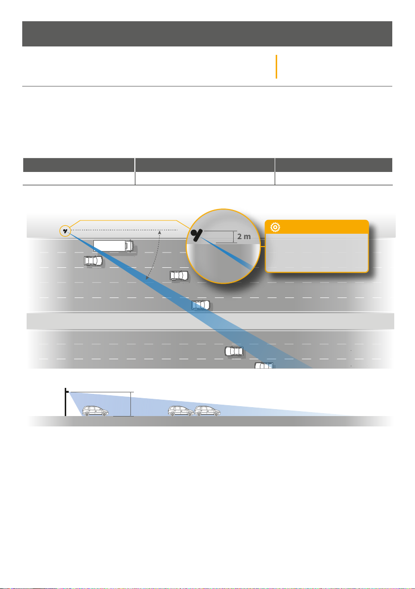
Oset: 2 metres
Height: 6 metres
Setup: AGD Align Visual
& Histogram
2 m
30º
CONFIGURATION:
AGD 343
MOUNTING LOCATION
The AGD 343 has been designed to be mounted on a variety of structures, where it looks across the carriageway
at 30 degrees to provide highly accurate traic data.
The detector must be mounted at a minimum height of 6m above the carriageway and at an angle of
30 degrees. The AGD align set-up tool assists in accurate set up of the angle.
Offset Recommended Mounting Height Acceptable Mounting Height
2m 6m 6m
HIGHWAYS MONITORING RADAR
2 m
30º
CONFIGURATION:
Oset: 2 metres
Height: 6 metres
Setup: AGD Align Visual
& Histogram
6 m
Mounting Location Considerations
The detector has been designed to monitor traic in inter-urban environments while maintaining resilience to
externl factors, however, care must be taken when choosing a mounting location.
Avoid where possible:
• Installing the detector where it points toward large reflective surfaces (such as signs, barriers and metal
retaining walls)
7
Installation
AGD 343
PHYSICAL INSTALLATION
343 Mounting Bracket Kit
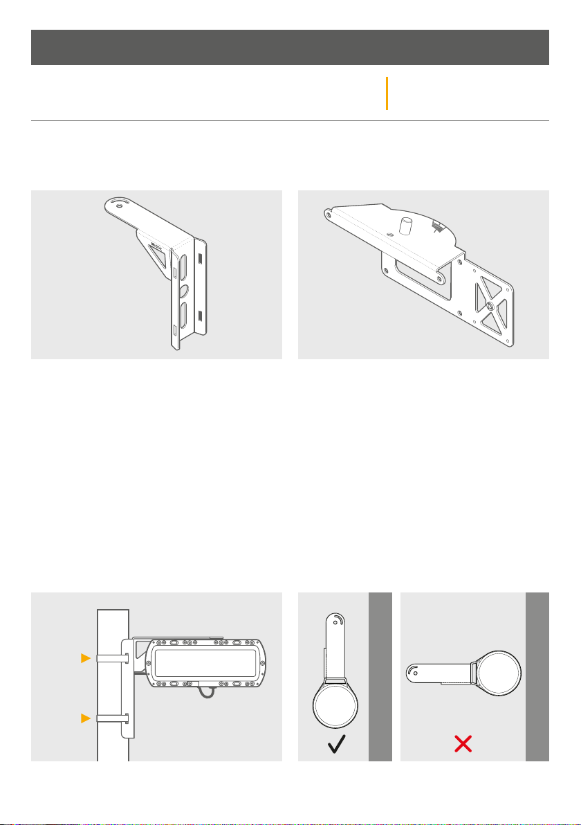
The AGD 343 bracket mounting kit (part number MS-246) consists of two brackets and all the required fixing
hardware.
BR-270 is the component of the bracket kit that BR-271 is the component of the bracket kit that
fits to the structure you are mounting to. fits to the rear of the radar.
Fixing hardware consists of:
7no. M5 x 10mm Torx T20 A2 Stainless Screws
7no. M5 External Shakeproof A2 Stainless Washers
HIGHWAYS MONITORING RADAR
Step 1 – Mount bracket to the pole
Attach BR-270 to the structure you are mounting too
using mounting straps (AGD recommends stainless
steel sign banding ½” thick).
The position of the bracket should be parallel to the
carriageway as in the image below, le. Do not install
the bracket as shown in the right hand image.
s
Pole
Pole
DIRECTION OF TRAVEL
8
s
DIRECTION OF TRAVEL
Installation
PHYSICAL INSTALLATION
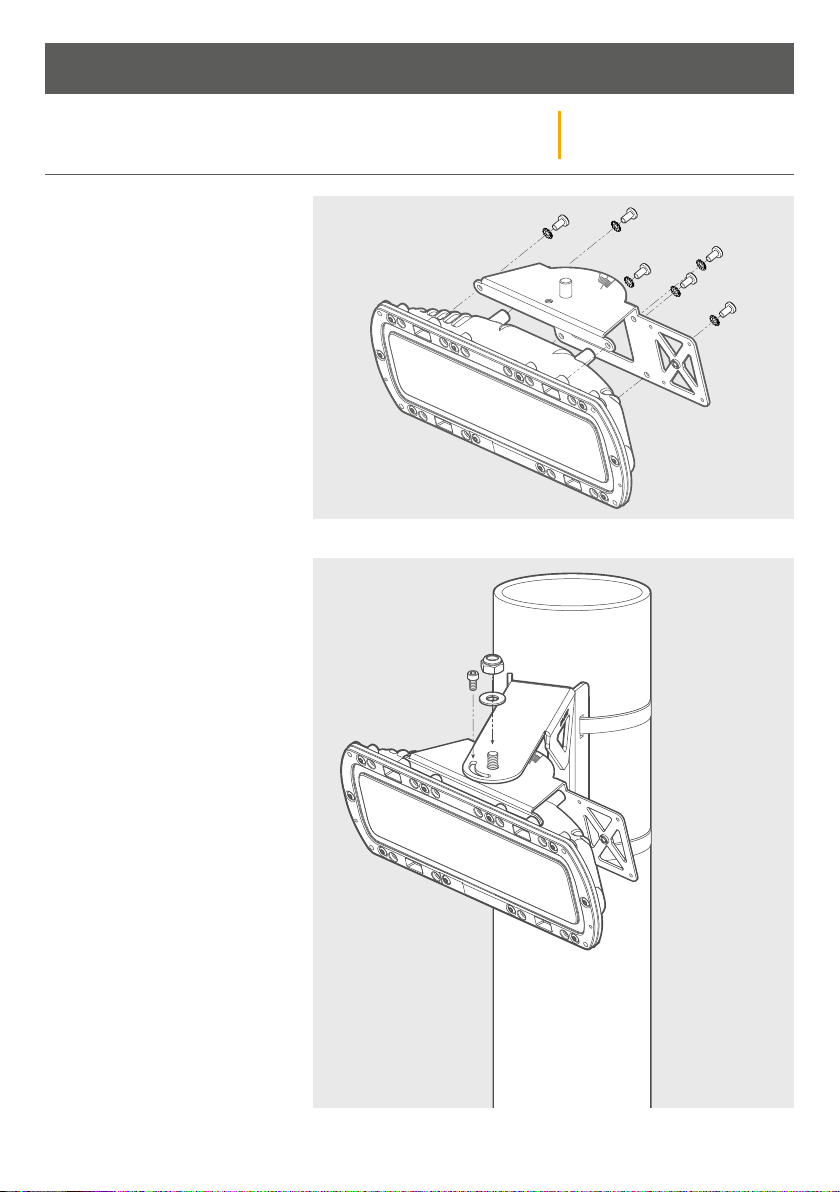
Step 2 – Mount bracket to the radar
Fit the six torx screws and washers and
tighten to a torque of 1.2Nm.
Step 3 – Mount radar to the pole
Insert the M10 Mounting Bolt through
the hole in the bracket on the pole,
loosely tighten the M10 Nyloc Nut.
Position the radar at roughly
30 degrees to the road, the etched
marks on top of the bracket will help
with alignment.
AGD 343
HIGHWAYS MONITORING RADAR
9
5
8
6 4
7 3
1 2
Installation
AGD 343
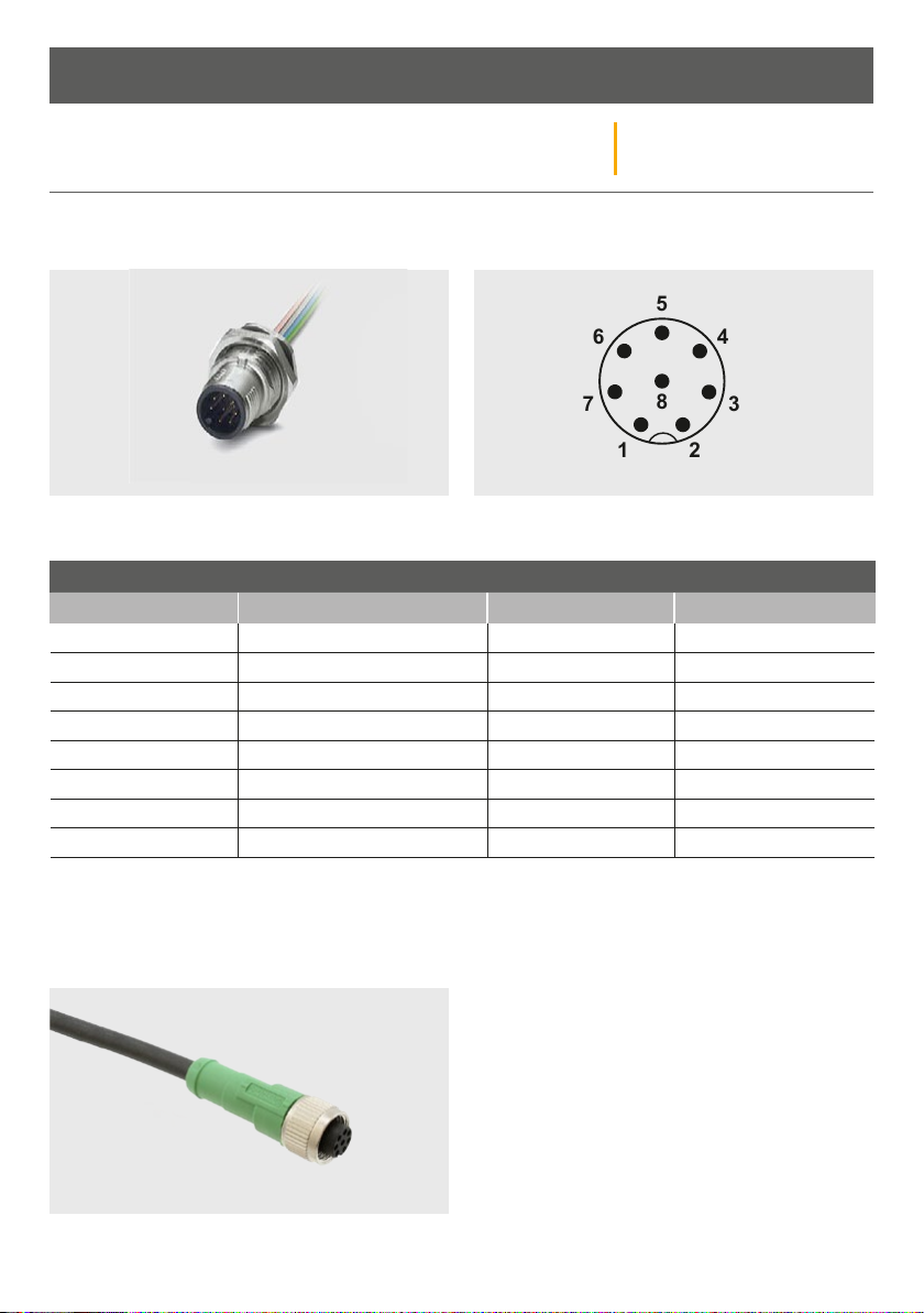
ELECTRICAL INSTALLATION
The detector is powered using a 24Vdc supply. The power is applied to the detector using the multi-pin mating
connector.
The product mating connector is shown above and is located on the bottom of the product.
CONNECTIONS
Pin No. Associated wire colour Function Additional Notes
1 White GND (0v)
2 Brown GND (0v)
3 Yellow Y (TX-)
4 Green Z (TX+)
5 Grey B (RX-)
6 Pink A (RX+)
7 Blue Vin
8 Red Vin
HIGHWAYS MONITORING RADAR
343 Power/RS422 Cable Assembly
The cable assembly to connect power and comms to the radar is Part Number CA-310. This cable is supplied in
a 10m length and is shown below:
CA-310 has the same attributes as shown in the Connections table above.
10
 Loading...