

Page 1

SERVICE TOOL
OPERATOR MANUAL
Electronic Diagnostic Tool (EDT)
22.01.2014
1
Page 2

2
Page 3

Electronic Diagnostic Tool (EDT)
CONTENTS
HARDWARE AND MAINTENANCE .................................................................................................................... 5
General Information ........................................................................................................................................... 5
Annual Subscription ........................................................................................................................................... 5
EDT Diagnostic Terminal ................................................................................................................................... 6
Diagnostic Terminal Components ............................................................................................................... 7
Touch Screen Sensitivity ............................................................................................................................. 9
Protective Bump Case ................................................................................................................................. 9
Suction Cup Work Platform ....................................................................................................................... 10
Convenience Kit ............................................................................................................................................... 11
Screen Cleaning Cloth .............................................................................................................................. 11
Screen Protector Replacement ................................................................................................................... 11
Cigarette Lighter Adapter .......................................................................................................................... 12
Docking Station ......................................................................................................................................... 12
2X4 CAN USB Vehicle Communication Interface ............................................................................................ 13
Modular Expansion System ............................................................................................................................. 14
Diagnostic Terminal Set-Up ............................................................................................................................. 14
Terminal Connections ............................................................................................................................... 15
Connecting to a Wireless Network ............................................................................................................ 15
Connecting to a LAN Network ................................................................................................................... 16
USB Port .................................................................................................................................................... 16
Care of the Diagnostic Terminal ...................................................................................................................... 17
Diagnostic Terminal Durability ................................................................................................................... 17
Cleaning the Screen .................................................................................................................................. 17
Replacing Screen Protector ...................................................................................................................... 17
EDT Software ................................................................................................................................................... 18
Registration ...................................................................................................................................................... 19
Region Set-Up ..................................................................................................................................................... 21
Software Updating ........................................................................................................................................... 23
Update Release Notes .............................................................................................................................. 25
Timeout and License Notification ..................................................................................................................... 25
On-Screen Keyboard ....................................................................................................................................... 27
Installing EDT Software to a Laptop ................................................................................................................ 28
Laptop Requirements ................................................................................................................................ 28
Installation Procedure ................................................................................................................................ 29
Using a Printer ........................................................................................................................................... 34
Non-AGCO Approved Software ................................................................................................................ 34
OPERATION ....................................................................................................................................................... 35
Getting Started ................................................................................................................................................. 35
Help ........................................................................................................................................................... 36
Home Page ................................................................................................................................................ 37
Unit Selection ............................................................................................................................................ 37
Language Selection ................................................................................................................................... 38
CAN-USB Presence .................................................................................................................................. 38
Utilities ....................................................................................................................................................... 39
Vehicle Selection ............................................................................................................................................. 47
Whole Machine Help Files ......................................................................................................................... 48
Diagnostic Connection Selection ..................................................................................................................... 49
Network Scan ................................................................................................................................................... 50
Network Summary ..................................................................................................................................... 51
3
Page 4

CAN Network Status ................................................................................................................................. 51
Diagnostics by Function ................................................................................................................................... 52
Graphical Diagnostics ............................................................................................................................... 53
Diagnostics Summary ............................................................................................................................... 54
Diagnostics Reporting ............................................................................................................................... 55
Calibration ........................................................................................................................................................ 59
Configuration .................................................................................................................................................... 60
Diagnostic Test ................................................................................................................................................ 61
Software Flash ................................................................................................................................................. 62
Software Package Flash (Multiple Files) ................................................................................................... 62
Individual File Flash ................................................................................................................................... 62
Diagnostic Trouble Codes ................................................................................................................................ 63
Active Codes ............................................................................................................................................. 63
Stored Fault Codes ................................................................................................................................... 65
Fault Tree Index ........................................................................................................................................ 66
CAN Trace ....................................................................................................................................................... 67
EDT LITE ............................................................................................................................................................. 69
EDT Lite Installation Creator ............................................................................................................................ 69
EDT Lite Installer ............................................................................................................................................. 74
EDT Lite Application ........................................................................................................................................ 75
INDEX ................................................................................................................................................................. 77
4
Page 5
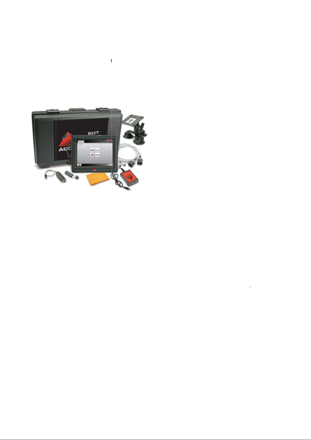
GENERAL INFORMATION
The EDT is used by dealership technicians to interface with specific machines that have a Cont
(CAN) BUS as part of the electronic system architecture.
FIG.1
EDT is a
protocol adapter, carry case, and other items.
A versio
software application, cables, and 2x4 CAN USB Protocol Adapter.
ANNUAL SUBSCRIPTION
The annual software subscription fe
dealership sells that are supported by the dealership. Software subscription is not charged by
The annual subscription fee covers continual tool functional improvements, sof
support for the EDT (hardware and software issues) based on the type of EDT kit purchased. The subscription fee also
covers a loaner program for EDT kits purchased with a diagnostic terminal.
If the annual subscription is
expiration date, but eventually will become non
plug and play
n of the EDT kit less the diagnostic terminal and associated parts is available. This kit will contain the EDT
diagnostic tool kit that contains a diagnostic terminal, vehicle connection cables, CAN BUS
HARDWARE AND MAINTEN
e covers machine software updates for all AGCO brands and product lines the
not renewed, the EDT application will work for a limited period of time after the renewal
functional (application will automatically lock).
ANCE
tware update process and technical
roller Area Network
-brand.
-
5
Page 6
6
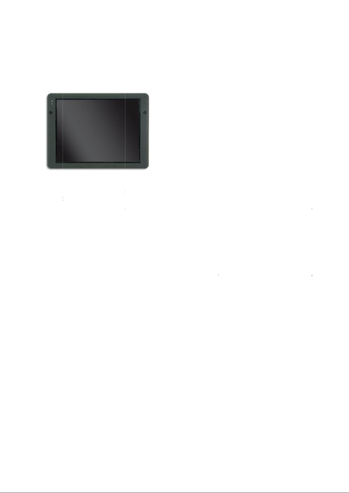
EDT DIAGNOSTIC TERMI
NOTE:
FIG.2
The EDT
other computer.
The EDT diagnostic
during use. The screen is fluid resistant (including oil) with a replaceable protective cover.
NOTE:
The EDT diagnostic terminal has an electronic keyboard program installed. The keyboard can be activated by the user
from within the EDT application.
The on
language requirements.
Make sure hands are clean of grease
diagnostic terminal is a tablet computer. The terminal has a network connection port and will function like any
It is advised to treat the EDT diagnostic terminal as a service tool and not an additional computer to include in
the dealership LAN network.
The diagnostic terminal needs to be available to the service technician at all times for use in repairing custome
machines.
screen keyboard is touch
terminal is semi
NAL
ruggedized which means the terminal will withstand moderate shock and vibration
screen activated, fully functional, and is presented in the reg
, water or excessive grime before touching or turning on the unit.
ional format based on
-
r
-
-
Page 7
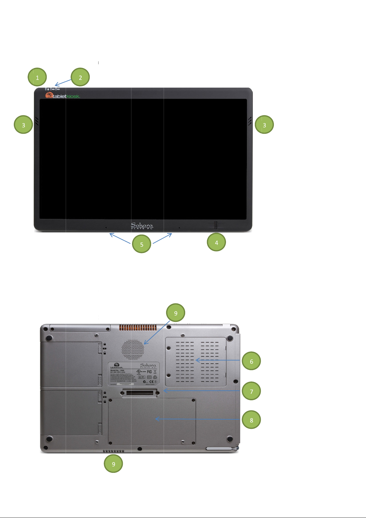
Diagnostic Terminal Components
FIG.3 &
Front
(1)
(2)
(3)
(4)
(5)
(6)
(7)
(8)
(9)
FIG.4
and back
Hard drive activity LED
Battery LEDs 1 and 2
Speaker
Fingerprínt Reader
Digital Microphone Array
RAM modules
Docking Connector Port
Hard Drive / Solid State Drive
terminal view
(2 SODIMM slots)
and CPU Intake Vents
Stereo
System
s
7
Page 8
8
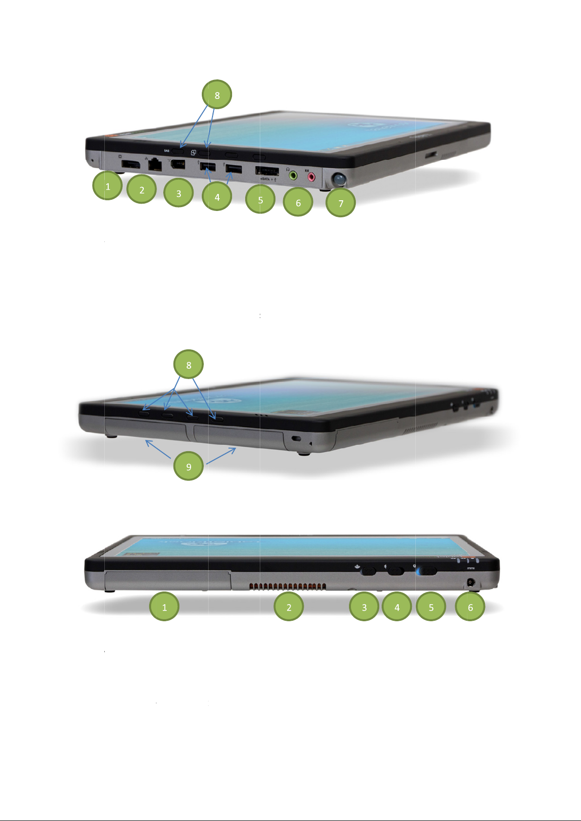
FIG.5 &
Left
(1)
(2)
(3)
(4)
(5)
(6)
(7)
(8)
(9)
FIG.7
Top terminal view
(1)
(2)
(3)
(4)
(5)
(6
IG.6- and right
Digital Video Out + Display Port+
Ethernet port (RJ45)
Firewire 400 (6
High Speed USB 2.0
eSATA
Audio Headphone Out and Microphone In jack
Pen in Garage
Function Buttons:
Lithium Ion Ba
Modular Expansion S
System Ventilation
Transmitter Power S
Bluetooth
System Power Switch
DC In (power in)
hand side terminal view
Ethernet port (RJ45)
SAS, Screen Rotation,
Transmitter Power S
witch
s
Touch Screen Lock, 3 User Programmable quick buttons
s
Gigabit
F
-
-pin)
ports
port
Stylus
tteries
lot
WiFi
)
witch
Page 9
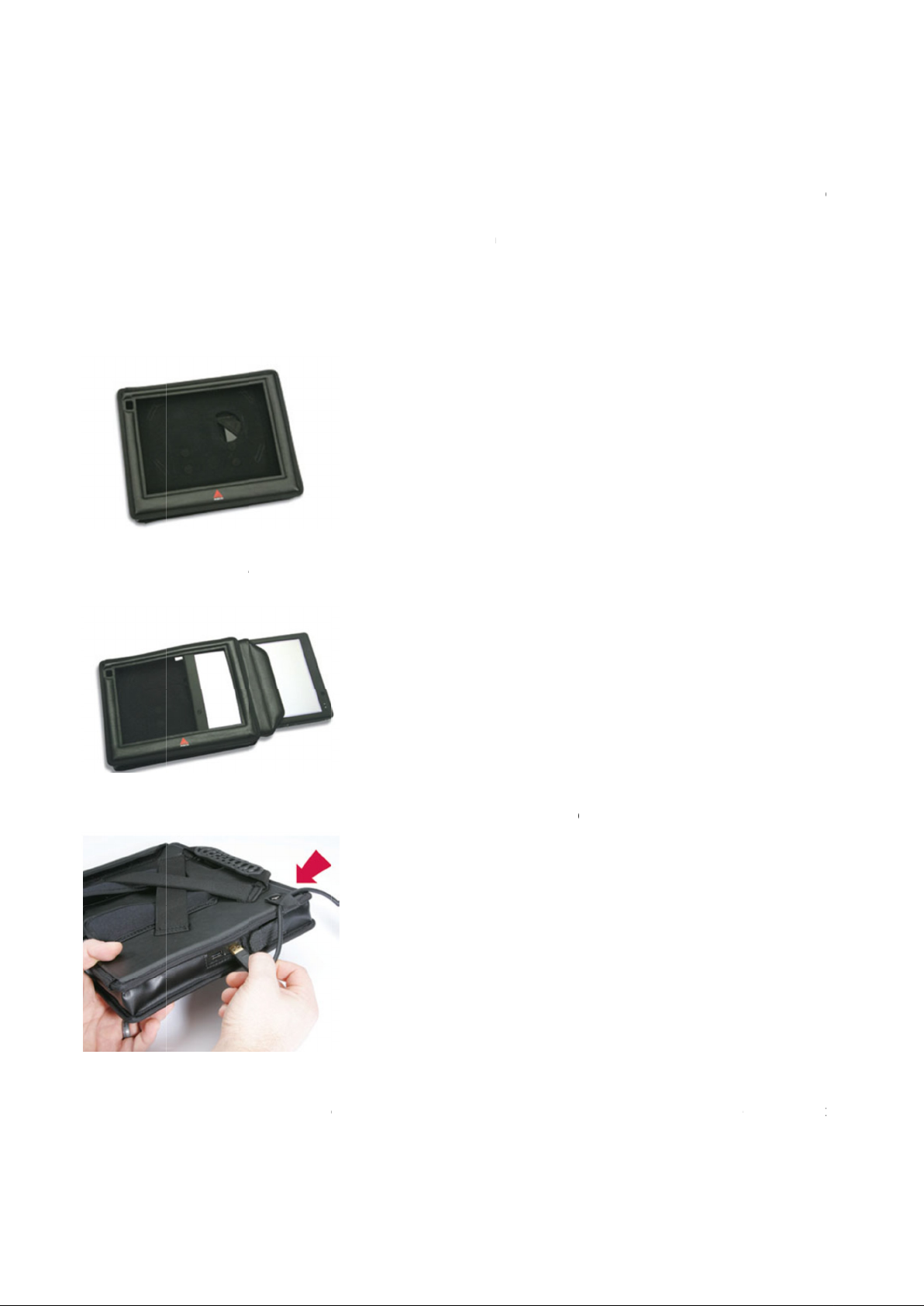
Touch Screen Sensitivity
The touch screen is resistive touch and requires some pressure to register a result. Do not use excessive force when
usi
IMPORTANT:
Protective B
FIG.8
The protective b
as well as impact.
FIG.9
To use the bump case, slide the d
FIG.10
Connect the
cable provides a convenient point for the
te
ng the touch screen. Smooth even pressure on the screen will result in prolonged screen life.
pencils, pens, screwdrivers or any other objects to touch
90 degree USB cable to the diagnostic terminal. Att
rminal USB port is not damaged.
Do NOT use any objects other than the stylus that comes with the terminal or a finger tip. Do not use
ump Case
ump case for the diagnostic terminal will provide reasonable protection against dust, dirt a
It is recommended the bump case be installed on the termin
iagnostic terminal into the bump case and close the access cover.
2x4 CAN USB protocol adapter, and provides a “break away” protection so the
the screen or damage can occur.
ach the cable to the bump case.
al during operation of the EDT.
The 90 degree USB
nd moisture,
9
Page 10
10
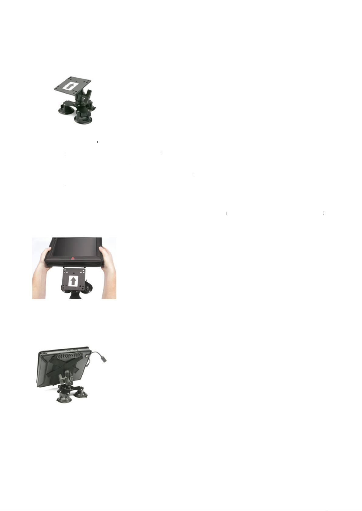
Suction Cup Work Platform
FIG.11
The suction cup work platform can be mounted on the vehicle cab window.
The diagnostic terminal can then be
IMPORTANT:
Make sure the window or other smooth surface is clean before attaching the suction cup work platform.
Attach the suction cup mount to the window BEFORE sliding the diagnostic terminal onto the mou
Place the suction cups on the window and twist the lock to the On position.
IMPORTANT:
FIG.12
Make sure the plate is orien
FIG.13
Slide the diagnostic terminal onto the mount.
NOTE:
glass or other smooth surface before installing the terminal ont
brace
Mount attachment will become easier with repeated use.
Make sure not to obstruct the view from the operator seat.
Make sure all three suction cups are latched to the On position, and have firm contact to the window
attached to the work platform, allowing hands
ted with the arrow pointing up.
o the mount.
free diagnostics.
Connect the arm and plate to the
-
nt.
.
Page 11

CONVENIENCE KIT
The EDT convenience kit comes with four items:
• • •
•
Screen Cleaning Cloth
FIG.14
The
terminal screen. The cloth is washable and reusable.
Screen Protector Replacement
FIG.15
The screen protector is made o
scratches and damage due to bumps. Use the screen protector to extend the touch screen life.
Screen cleaning cloth
Screen protector replacements pack
Cigarette lighter adapter
Docking station with power adapter
bright orange microfiber cleaning cloth is used for removing dust, dirt, and oily smudges from the diagnostic
f a durable material and is self
adhesive. The screen protector helps to prevent screen
11
11 12
-
Page 12
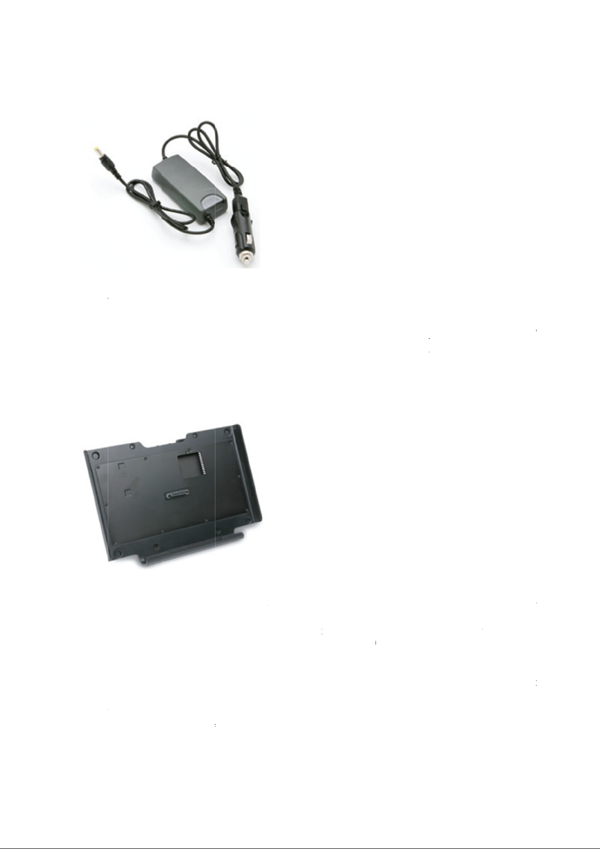
Cigarette Lighter Adapter
FIG.16
Use the
for 6V or 24V systems.
Recharge the diagnostic terminal battery in the field by plugging the DC adapter into the terminal. The DC adapter ca
remain plugged into the diagnostic terminal for extended periods, and is recommended for use during vehicle software
reflashing procedures where loss of terminal power during the procedure could lead to vehicle controller damage.
D
FIG.17
The docking station provides a pass
allowing the ability to charge and connect easily with the terminal in a secure storage position.
The dockin
This allows the t
multiple cords.
To insert the termin
and push back to make the connection. An
terminal is ON.
Pull from the top of the ter
After removing the diagnostic terminal from the docking station, insert the terminal into the bump case.
Connect the 90 degree USB to diagnostic terminal. Attach the cable to the
cigarette lighter adapter by plugging into the 12V cigarette lighter adapter receptacle of the machine. Do not use
ocking Station
g station can be connected to an external monitor, keyboard, mouse, AC power, and internet connection.
erminal to be docked, recharged
al, remove from the bump case. Place the lower edge of the diagnostic terminal into the dock first
minal to remove. A
thru of all functional ports on the diagnostic terminal, including power and internet,
and receive required updates for the software without connection of
upchime
downchime
sound from the system will verify connection to the dock if the
sound from the system will verify disconnection.
bump case.
n
-
Page 13
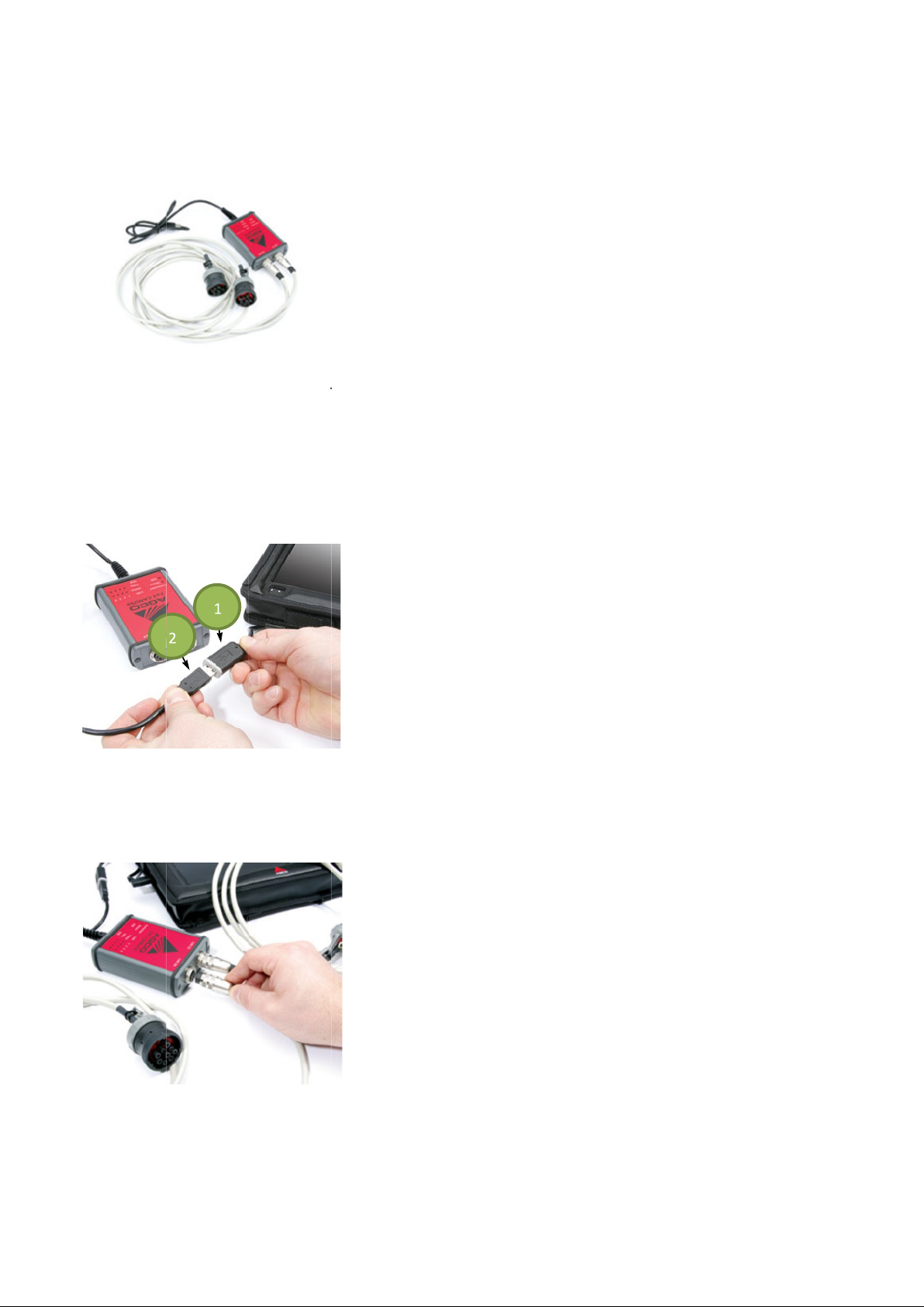
2X4 CAN USB V
FIG.18
The
on a singl
The CAN USB protocol adapter provides the communication link between the ECUs on the vehicle and the EDT
software application.
The cables plug into the vehicle side of the 2x4 CAN USB and can be used either i
FIG.19
Connect the 90 degree USB (1) to the 2x4 CAN USB (2).
IMPORTANT:
FIG.20
Connect the vehicle side cables to th
manual for connection inform
CAN USB protocol adapter for EDT is a 2x4 channel adapter capable of reading four CAN BUS network channels
e vehicle (two channels at once).
EHICLE COMMUNICATION
It is highly recommended the 90 degree USB cable be used for all USB connections to the terminal.
e 2x4 CAN USB protocol adapter.
ation to the electrical system for the machine.
INTERFACE
Follow the instructions in the machine’s service
ndependently o
r in combination.
13
13
1
2
Page 14
14
MODULAR EXPANSION SY
EDT tablet
adding specific modules. These modules can be example
P.O.S module. The expansion module can be added or removed without having to shut down or restart the system.
Please note that you have to install the corresponding driver before you plug in the module for
The expansion module
the edge of the terminal which prevents the terminal from being used with the case. Since the terminal must be removed
from t
EDT technical support will be limited for these devices.
FIG.2
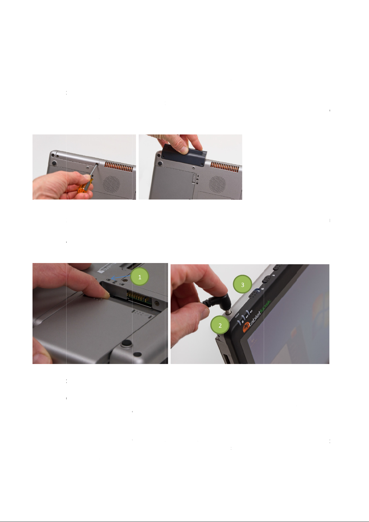
To add the expansion module: Open the screws and remove the cover
secure it with two screws.
DIAGNOSTIC TERMINAL
NOTE:
FIG.23
Insert the battery packs
hear a click when the battery is properly seated. Then slide the battery
Locate the AC adapter and the power cord
connection cable into the DC In port (2) on
plug the power cord into an external power socket.
IMPORTANT:
The
switch emits a blue glow (about 2
When the system powers on for the first time, Windows
PC features a modular expansion system that allows you to add task purposed functionality simply by
he case to use the expansion module
1 &FIG.2
Make sure hands are clean of grease, water or excessive grime before touching or turning on the unit.
FIG.24
power for the first time.
power switch (3) on the top of the terminal is the main power toggle. Slide the switch to the right and
slot cannot be accessed with the terminal inside the bump case. Most devices extend out past
2
and make sure that they are locked. Align the battery in the bay and slide it into place. You will
Allow the battery to charge fully before disconnecting the diagnostic terminal and running on battery
STEM
SET
4 seconds). Release the switch. The diagnostic terminal will now boot up.
slot, along with the power requirements, use these devices only as needed.
. Plug the power cord securely into the AC adapter. Plug the AC adapter
top of the diagnostic terminal.
USB x2 adds,
may have a few questions in order to localize the installation.
WWAN module adds, SCAN module adds or
. Press down gently to
locking tab up to the locked position (1).
Once the adapter plug is securely in place,
the first time.
attach the module and
hold until the
&
-UP
-
-
®
Page 15
Terminal
The diagnostic terminal is wirelessly capable of bluetooth connections and 802.11a,b,g Wi
FIG.
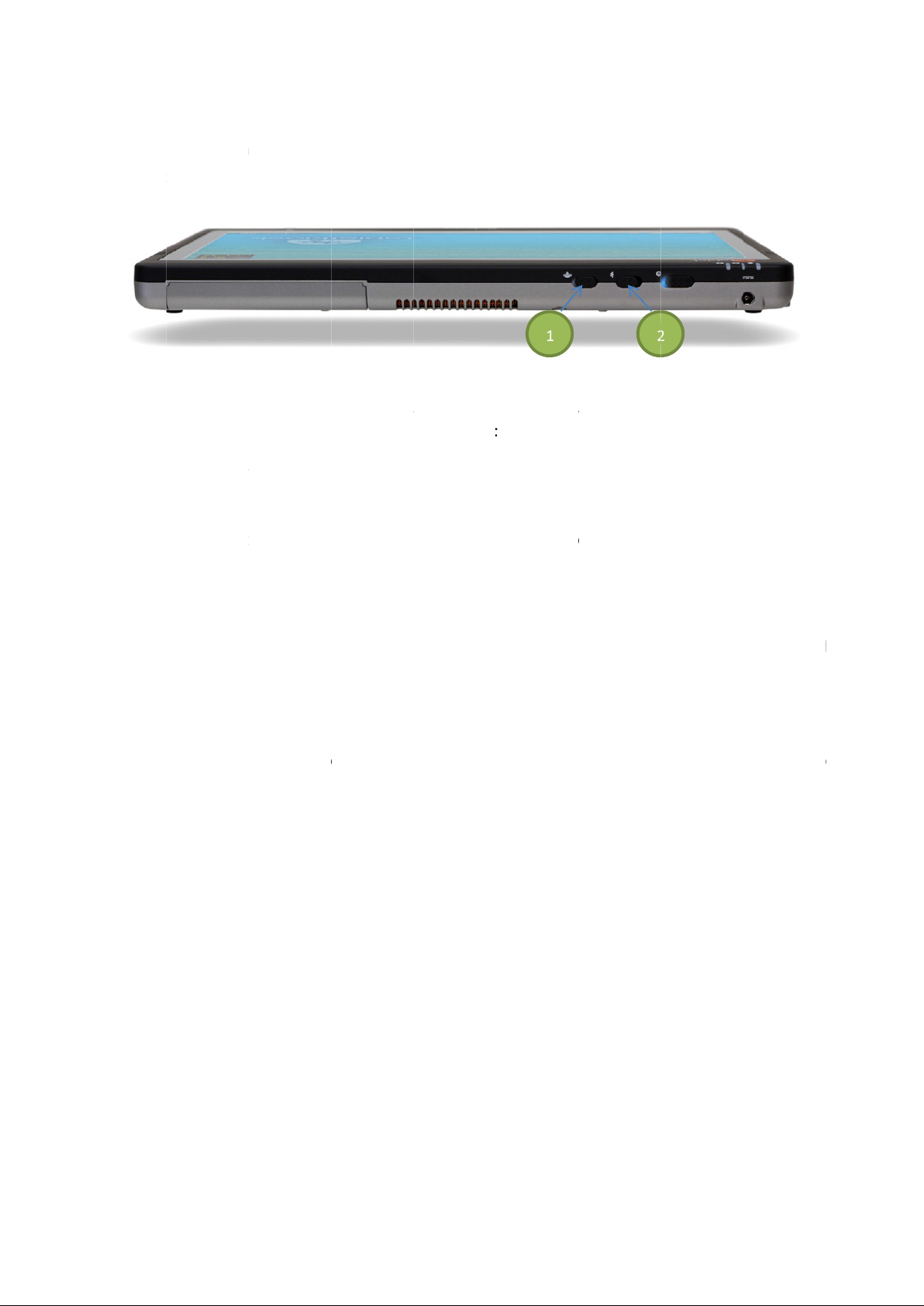
To use 802.11 networks, make sure the switch (1) at the top of the diag
Panel > Network and Sharing Center > Set up a new connection or network
For bluetooth connections, make sure the switch (2) at the top
Progr
Connecting to a Wireless Network
Turn on the WiFi transmitter using the toggle switch (1) on the top of the diagnostic terminal.
After that the wireless networking icon a
From the list that appears, choose the network to connect to and select the
If no wireless networks appear after a few moments, select
If the wireless network is security
entered correctly in both text fields or connection to the network will not be possible. Your network administrator should
be able to supply the network key.
If the network key is entered
your networ
The diagnostic terminal is also capable of wired connections. Ethernet connections and landline modem connection
ports a
work
provider for connection questio
and Internet
k administrator for assistance.
re connected at the left side of the terminal. Modem connections are not recommended but are available as a
around if no wireless or Local Area Network/Ethernet access is available. Contact your dial
for connection instructions.
Connections
enabled, a
correctly, you should now be connected wirelessly. If you have trouble connecting, contact
ears on the Windows Task bar.
dialog box will be shown requesting a network key. The key must be
of the diagnostic terminal is O
Refresh
nostic terminal is
Connect
--Fi connections.
for connection instructions.
-
Start > Control
n and select
up internet service
15
All
15
On
25
and select
ams >
-
Bluetooth
ns.
Start >
pp
icon.
in the left
-
hand pane.
-
Page 16
16
Connecting to a LAN Network
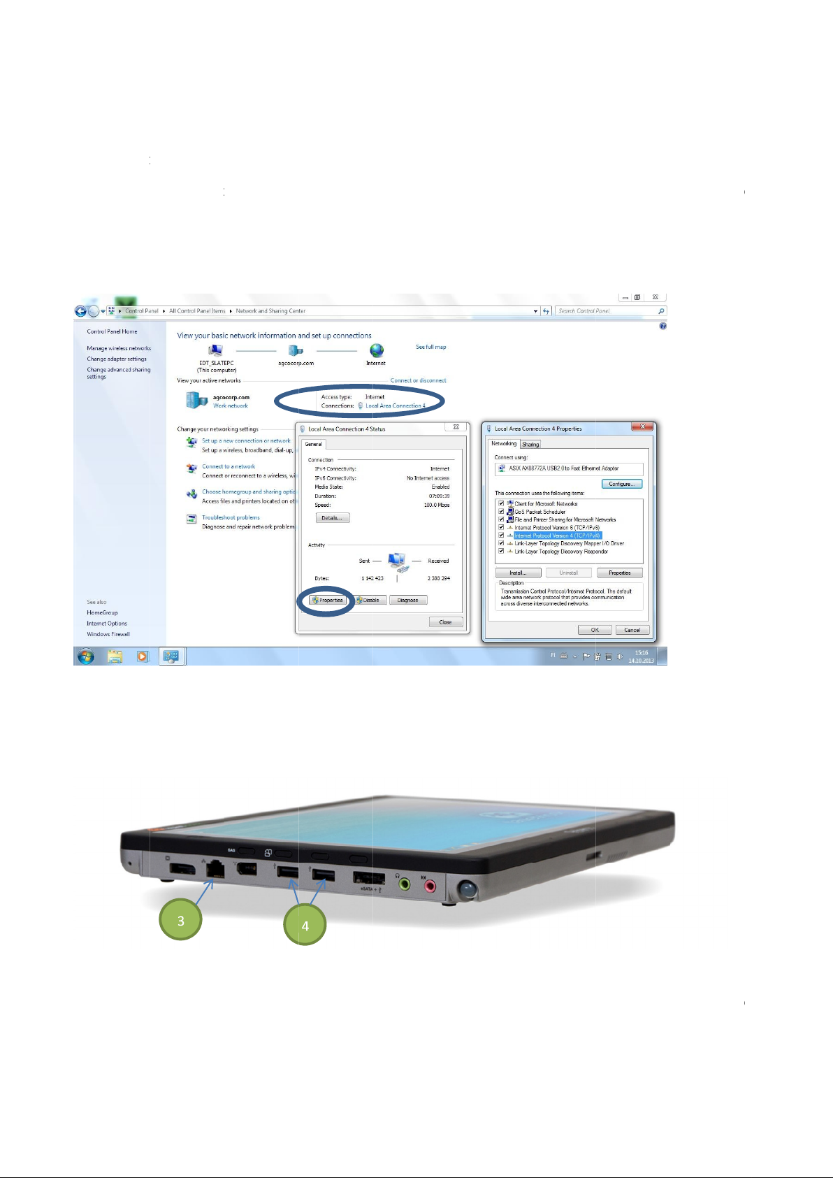
The diagnostic terminal is designed to connect to the inter
via a wired LAN environment, typically an Ethernet port must be
If the ability to connect to the internet and view web sites in a web browser is available to the dealership, then
connecting the terminal for registration and software updates is possible.
Your ED
found
service before calling EDT
FIG.
It is possible also determine the internet settings
USB Port
FIG.
The USB 2.0 ports (
recommended that for larger peripheral devices, use of AC powered USB devices over USB powered devices be used
for best results. Low power devices (USB memory devices, SD Card readers) can be us
consideration
T tablet computer should detect the local internet connection automatically.
from Tablet Kiosk Users Guide.
274) can be used to connect any number of Windows
If there are issues connecting to the web, contact your LAN administrator to verify
technical support.
manually via Network and Sharing Center under Control Panel.
t over standard internet port (3
within the reach of the networking cable you are using.
he proper instructions
roved peripheral devices. It is
To connect to the Internet
ed without power
can be
ne
).
T
26
s.
®
app
Page 17

CARE OF THE DIAGNOSTIC TERMINAL
Diagnostic Terminal Durability
The diagnostic terminal is semi
The terminal must not be subjected to extended use in direct sunlight, temperature extremes, rain or excessive
moisture.
IMPORTANT:
Cleaning the Screen
FIG.
Remove the orange microfiber cleaning cloth from the kit package and wipe the screen free from smudges.
Take care to only wipe the edge of the screen parallel to the s
can be used.
NOTE:
If these methods do not clean the screen, replace the screen protector with a new one.
IMPORTANT:
Replacing S
The screen protector is attached at the edges of the screen only.
FIG.
Turn the diagnostic terminal off and slide out of the bump case. Using a fingernail or some other non
lift the screen protector off
residue.
The new screen protector will have a blue film on the back side (the side that faces the screen) to protect against
smudges and fingerprints. Wash hands
edges to expose the adhesive, leaving one of the side strips intact for handling.
Align the screen protector with the terminal screen. Press down the adhesive exposed side and ca
protector in order to peel off the remaining paper strip. Press along the edges of the screen to secure the screen
protector.
NOTE:
rotect the terminal from damage.
Replacement cleaning cloths are available. See the EDT website for details.
Additional screen protectors are available. See the EDT website for details.
Use the bump case and 90 degree USB to USB adapter provided in the kit AT ALL TIMES in order to
DO NOT use cleaning agents or solvents on the terminal screen.
creen Protector
rugged, but is NOT ruggedized with a s
at a screen corner and peel away. Wipe with the microfiber cleaning cloth to remove leftover
before removing the blue film. Peel off three of the four paper strips on the
creen edge. In some cases a slightly damp soft cotton rag
hock protected hard drive.
scratching edge,
refully roll back the
17 17 18
-
p
28
29
-
Page 18
EDT SOFTWARE
FIG.30
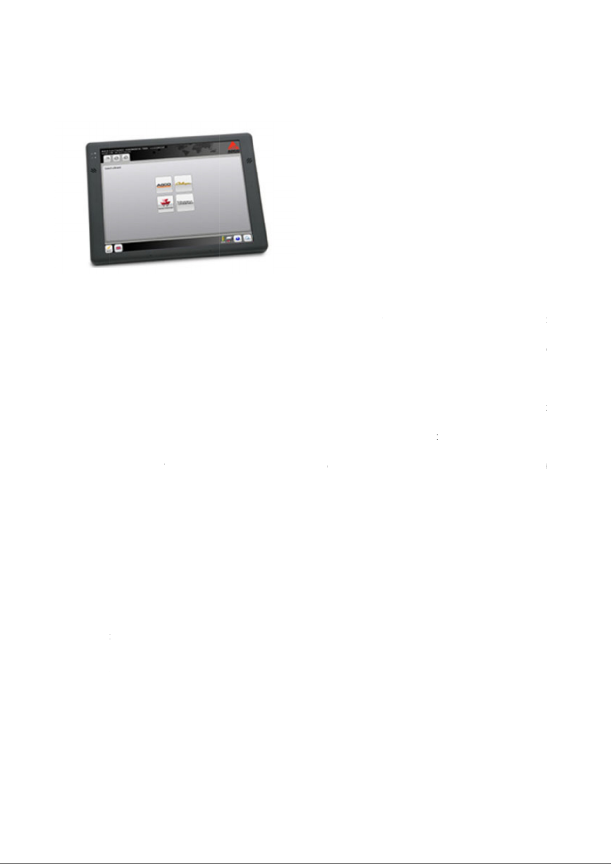
The EDT diagnostic terminal has all EDT software loaded and ready for use.
The EDT software application contains diagnostic troublesho
technician in repairing supported machines.
The EDT software application has an on
from within the application at any time.
NO
Security is built into the EDT application and software upgrade process. This allows a dealer access to only the
diagnost
IMPORTANT:
Examples of functionality of the EDT software application:
• • • • • • • • • • • • •
The EDT application will work on a traditional laptop, but will require an external or touch
program functions.
ic software to brands for which the dealer is contracted with AGCO to service.
terminal and/or any resident laptop. This makes technical support o
If additional software is installed, the EDT software application as well as other software programs may stop
functioning.
Touch screen
Ability to access multip
Full network scan and ECU status reporting
Active and Inactive ECU error message retrieval
Integrated ECU error message diagnostic troubleshooting trees
Troubleshooting trees specifically autho
CAN BUS network tracing and save feature, and ability to export the trace
Diagnostics by system
Software flash to multiple or single ECUs
Full configuration of ECUs
language selection capability from within the tool
ftware updates and upgrades using an internet connection
Ability to activate some third
It is highly recommended to have ONLY the EDT software application installed on the EDT diagnostic
le brand specific diagnostic software using a single interface
party support software from within the EDT application
board Help menu that shows how to use the application, and can be accessed
red for individual errors codes
oting trees for ECU error codes, which will assist the
f the EDT much simpler if necessary.
pad mouse to activate
TE:
-
-
MultiSo
-
Page 19
REGISTRATION
FIG.31
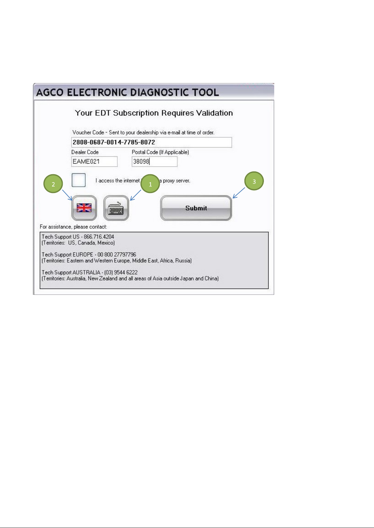
When the EDT is first turned on, the above screen will be displayed.
Select the keyboard icon (1) to display the On-Screen keyboard. For information on the On-Screen keyboard, see
On-Screen Keyboard on page 27.
Select the language by pressing on the Language icon (2).
Fill in the complete Voucher Code, your Dealer Code, and Postal Code (if applicable).
Select the Submit icon (3) to validate.
NOTE: The Dealer code and postal code entered must be identical to those used when the kit was ordered on the EDT
website.
19
Page 20
20
FIG.32
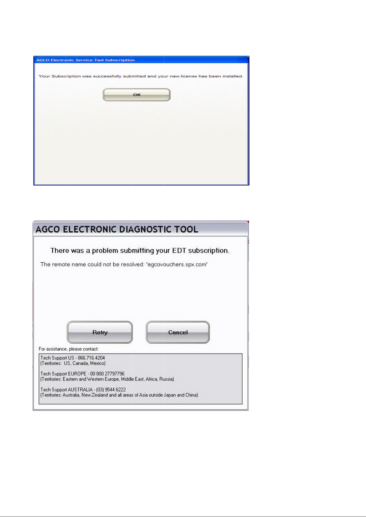
If the validation is successful the
FIG.33
If the entry was not valid the above screen will
RETRY
the submission or
above screen will be displayed.
out of the licensing process.
be displayed.
CANCEL
Page 21
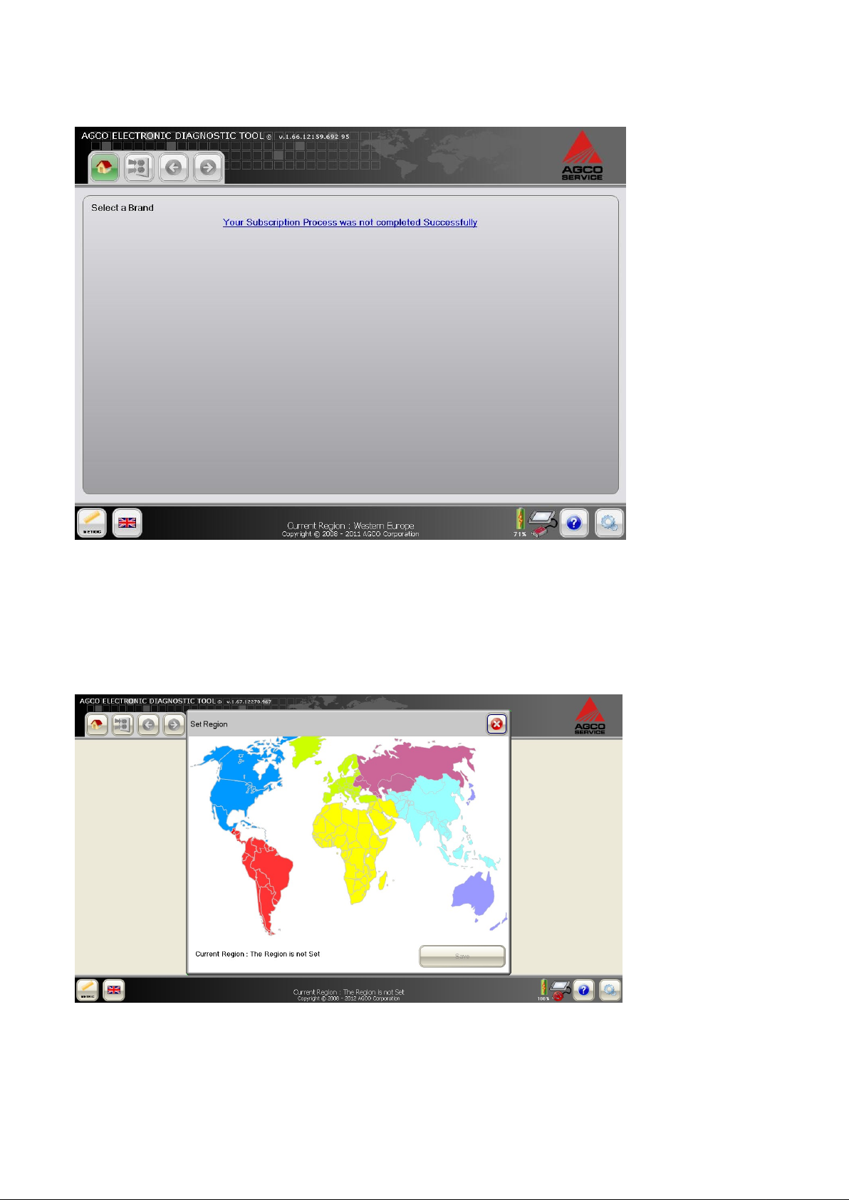
FIG.35
FIG.34
If CANCEL is selected on the previous screen, and if you try to load the EDT to bypass the registration process, the
EDT brand selection page shows the message displayed. If registration cannot be completed, contact the appropriate
Technical Support location as listed on the screen.
REGION SET-UP
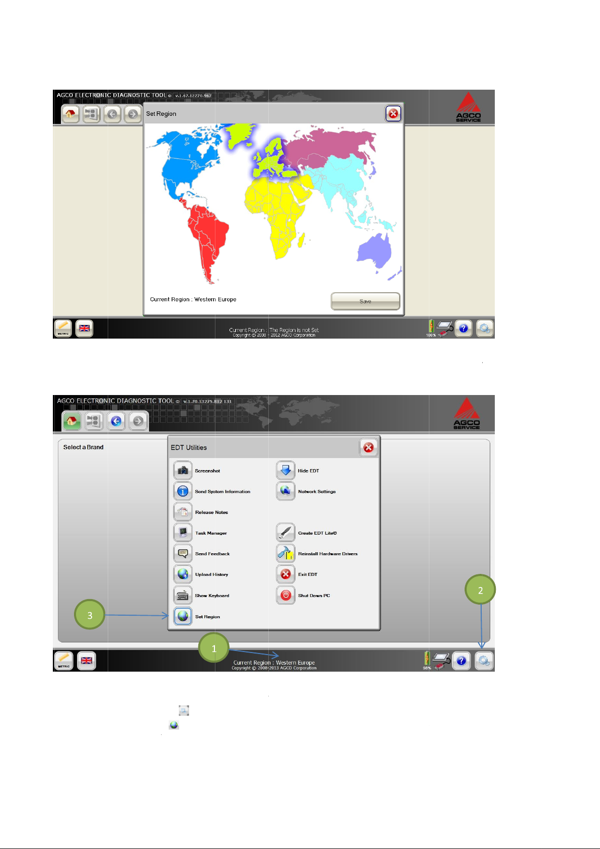
After the registration process has been completed the EDT will prompt to select a region when turned on for the first
time.
21
Page 22
22
FIG.36
Select the region that represents the country where the EDT is currently be
FIG.37
The region will be displayed at the bottom of the EDT main screen
setup, select the Utilities
Select the Set Region icon
be shown at the bottom of the EDT main screen.
icon
) on the bottom right
The Region menu will appear. Select the region. Select SAVE.
hand corner of the EDT screen.
ing operated from. Select SAVE.
To change the region a
The Utility Menu will appear.
t any time after the i
The new regi
nitial
on will
(2
(3).
-
(1).
Page 23
SOFTWARE UPDATING
Software updates will be managed and completed using the internet for each individual EDT. Software updates will be
handled through the software management service of an external technology partner. This service will manage each
EDT kit account based on the Dealer code and terminal identification. A dealership will be able to access and receive
software updates only for the AGCO brands the dealership has a contractual agreement to sell and service.
To complete all software updates a standard internet connection is required. No specialized modems or converter
equipment are required. High-speed connections are preferred, but not required. Slower speed connections will have
performance impacts but not functional restrictions.
The following options are available to the dealership that has no connection to the internet at the Dealership location:
• Obtain an internet connection at an alternate location outside away from the dealership. This connection can be
completed with a wireless or LAN connection cable using the on-board connection capabilities of the EDT
diagnostic terminal.
• Obtain and install a cellular telephone connection card into the EDT diagnostic terminal (Modular Expansion
System). The dealership will have to subscribe to a provider network for connection and data transfer to the
internet.
To check for software updates:
• Turn on the diagnostic terminal.
NOTE: The EDT can be updated using the diagnostic terminal alone or inserted in the docking station.
• Make sure the EDT application is shut down.
• Connect the diagnostic terminal to the internet.
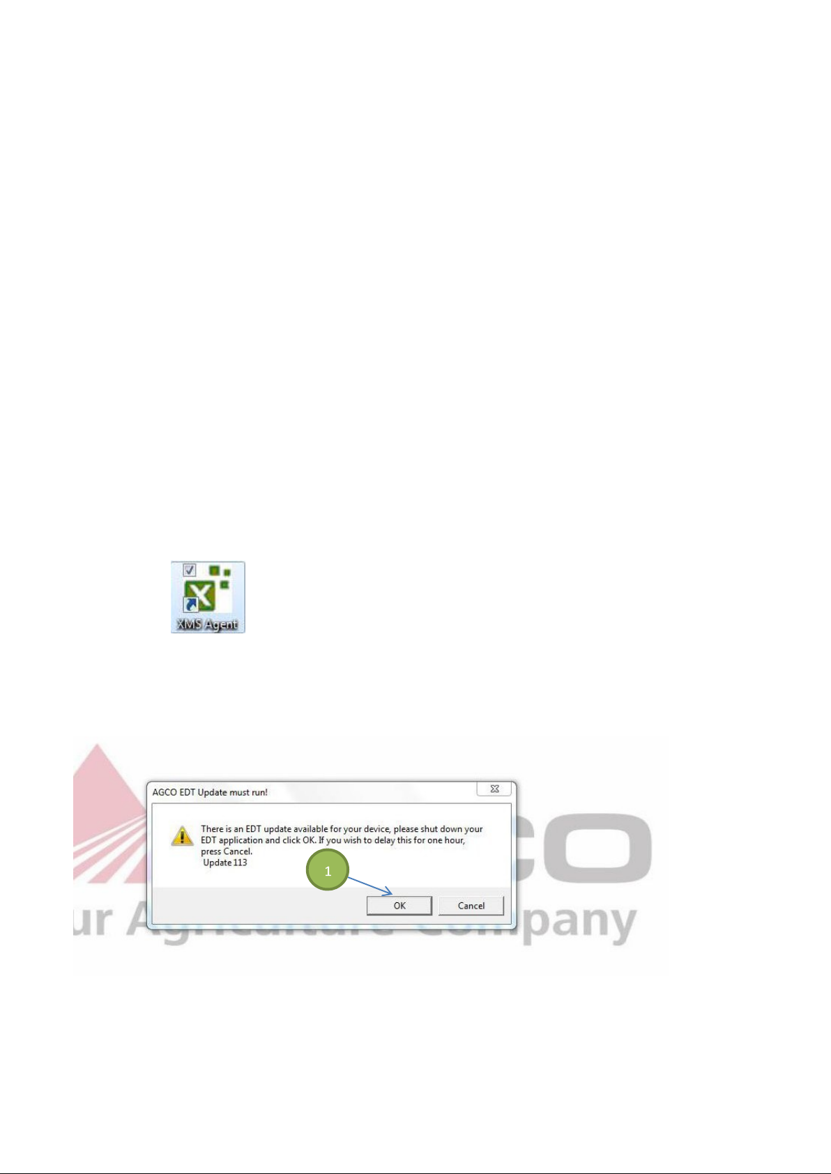
FIG.38
Look for the update process notification icon on the desk top.
IMPORTANT: DO NOT disconnect or shut down the diagnostic terminal as data is being downloaded.
NOTE: When connected to the internet, the EDT checks for updates every 15 minutes.
FIG.39
After the download has been completed, a popup is shown which allows the user to decide whether or not to install the
update now or wait one hour to be prompted again. After selecting the OK icon (1), the system will start installation.
23
Page 24
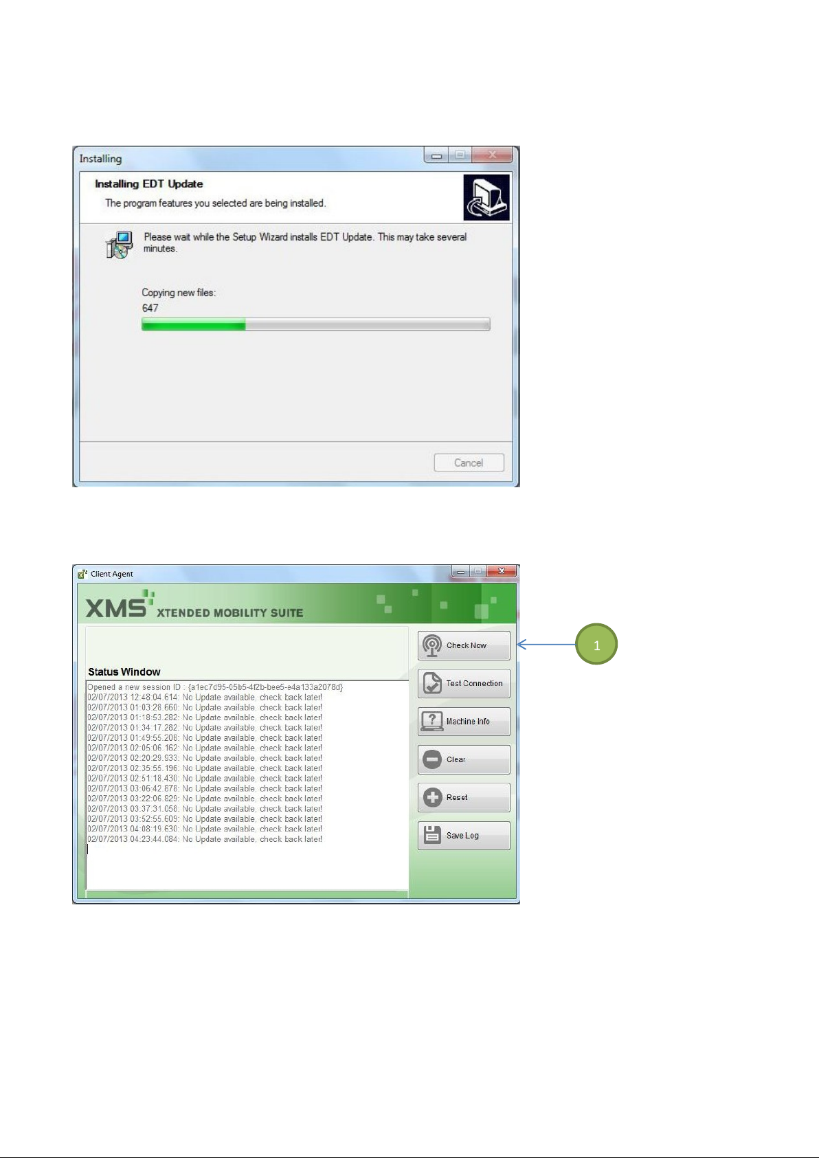
FIG.40
After the update has been installed, the updated EDT and new vehicle content will be available.
FIG.41
It is possible to check for an update at any time by double pressing on the XMS Agent icon in the desk top.
This dialog box will appear after the icon is selected. Package size and progress is shown.
Force a check for updates by selecting the Check Now icon (1).
24
Page 25
Update Release Notes
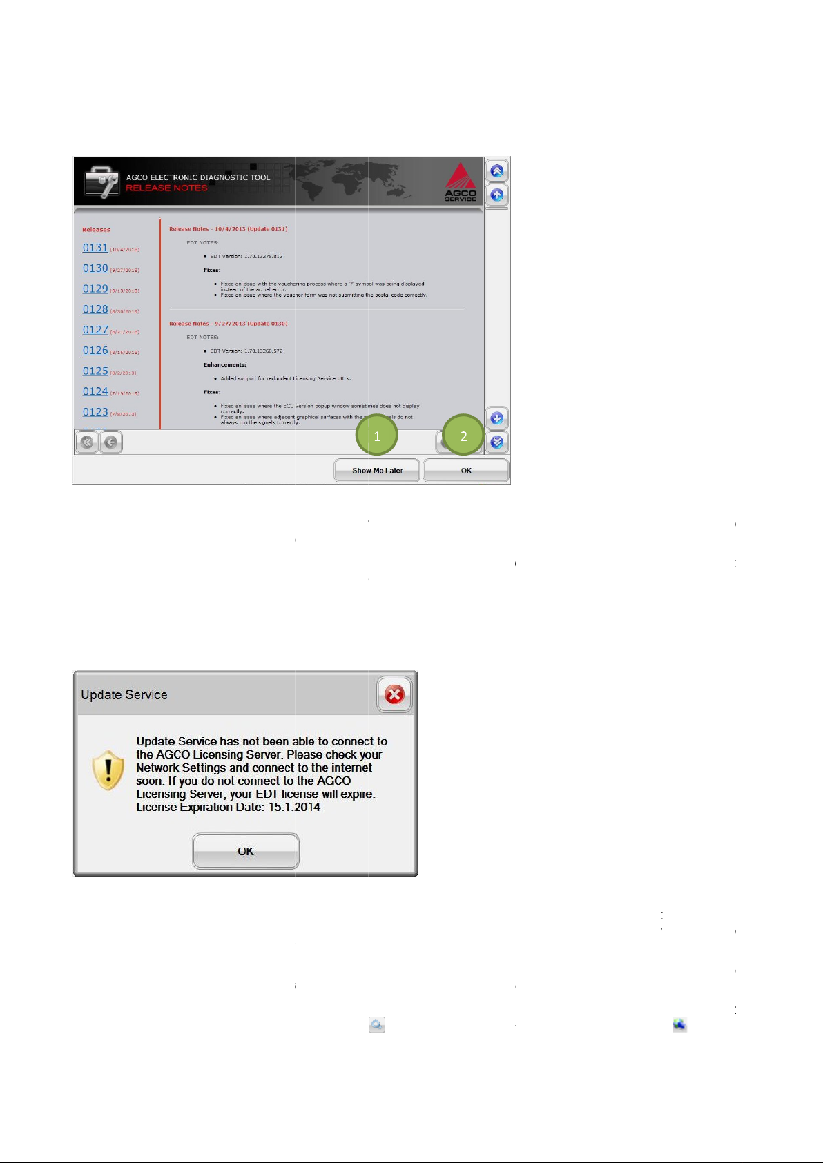
FIG.42
After a software update, a screen will be displayed with Release Notes explaining the reason for the upd
will be shown to the user after every update.
If the
OK
NOTE:
TIMEOUT AND
FIG.43
The
message is a notification to the user, but does not interfere with the operation of EDT. This message will di
the EDT goes more tha
N
and this message is still displayed, there is something wrong with the connection.
If this message is displayed, select OK and connect the
license still does not update, select the Utilities icon
Show Me Later
icon (2) is selected, the Release Notes will not be shown again until t
Currently these release notes are not translat
Update Service message is shown when a prob
Make sure to regularly allow the EDT to connect to the internet.
icon (1) is selected, the Release Notes will be displayed when entering EDT the next time. If the
LICENSE NOTIFICATION
n 5 days without connecting to the licensing server.
ed and will only be in English.
lem has been determined with the license update process. The
EDT to the internet. The license will automatically update. If the
on the EDT and select the Network Settings icon
he EDT is updated again.
If the EDT is regularly connected to the internet,
ate. This screen
25
splay when
25 26
OTE:
.
Page 26
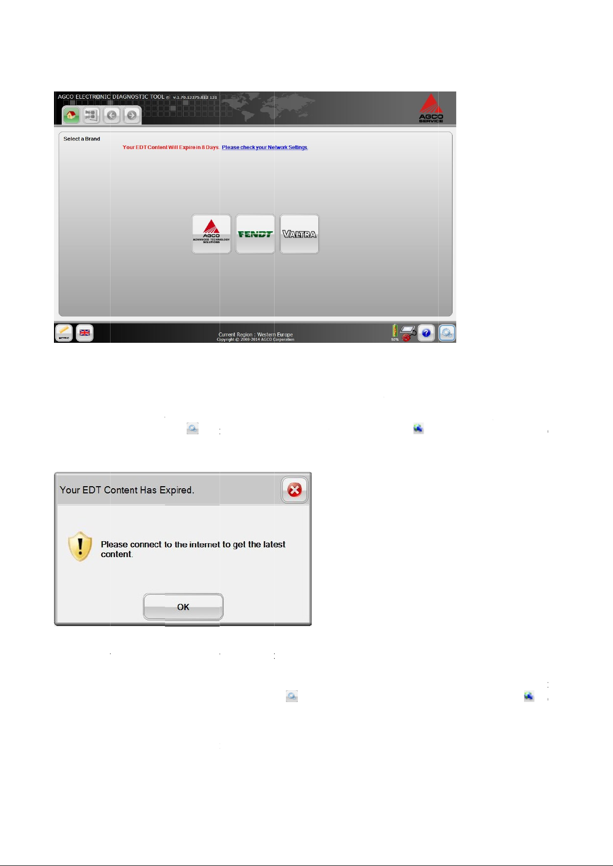
FIG.44
date approaches.
A message will be displayed when the subscription license is nearing the end of the valid subscription period. This
message will note the number of days remaining until the subscription license w
If this message is displayed, connect the EDT to the internet and the license will update itself. If the license still does n
update, select the Utilities icon
4
FIG.45
Failure to correct the connection issue will result in the message
be inoperable.
If this message is displayed, select OK and connect the EDT to the internet. The license wi
license still does not update, select the Utilities icon
Network Settings on page 4
IMPORTANT:
result in a failure to update the license.
If the above situation is not correct, the following message will be d
6 for more information.
that on the EDT and select the Network Settings icon
6 for more information.
the system time and date are accurat
on the EDT and select the Network Settings icon
e for your region. Incorrect time and date settings will
isplayed as the current license expiration
Your EDT Content Has Expired
, see Network Settings on page
ll automatically update. If the
. The EDT will now
, see
ill expire.
ot
Verify
Page 27
ON
FIG.46
An on
Whenever keybo
FIG.47
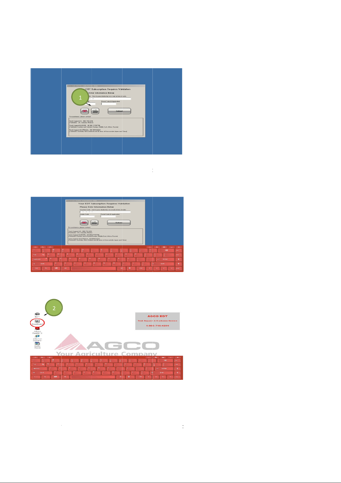
When the keyboard icon is selected, the keyboard is loaded.
If the keyboard is needed for other use, there are two ways to access.
One way to access the
(double press) the icon to activate from the desktop.
Another way to access the on
FIG.48
SCREEN KEYBOARD
screen keyboard automatically appears if text input is required for a specific EDT application function.
ard input is required, a keyboard icon (1) is supplied on the display.
EyesBoard™
screen keyboard is by selecting
application is an icon (2
) available on the desktop of the terminal. Double click
Start
EyesBoard™
27
-
1
-
1
-
then
.
Page 28

Recommended PC Requirements for
Minimum PC Requi
rements
Optimal Performance
Limited
Performance
Hardware
Industrial
laptop
computer
or semi
Semi ruggedized touch screen computer,
Proces
sor
Intel
Celeron
1.4
GHz
or
Intel
Core
1.7
GHz
1.2 GHz Intel processor or higher (or
RAM Memory
4
GB RAM
1GB RAM
Hard Drive Memory
320
GB hard drive (30
0 GB of free space)
120 GB hard drive (100 GB of free space)
Display
12.1 inch
TFT
W
XGA LCD wide angle
12.1 inch TFT XGA LCD wide angle
Pointing Device
Dual mode active
digizer +
Passive resistive touch screen
or
Microsoft
®
Ports
High Speed
USB 2.0 port
USB 2.0 port
Network Interface
1 x RJ
-
45 10/100/100
0 M
bps full duplex
1 x RJ
-
45 10/100/100 Mbps full duplex or
Expansion Module
Recommended
Recommended
Bluetooth
Recommended
Recommended
INSTALLING EDT SOFTWARE TO A LAPTOP COMPUTER
NOTE: The following information applies to EDT kits purchased without a diagnostic terminal.
The software installation for EDT comes on a separate CD for installation to a laptop.
IMPORTANT: It is highly recommended to have ONLY the EDT software application installed on a designated laptop.
This makes technical support of the EDT much simpler if necessary.
If additional software is installed, the EDT software application as well as other software programs may stop
functioning.
If purchasing the EDT kit without a diagnostic terminal, the dealer will receive limited technical support for the EDT
application only. There will be no hardware support for the designated laptop.
Install the EDT software onto the designated laptop, and complete all administration required to make sure the software
application and 2x4 CAN USB protocol adapter function properly. Also make sure the laptop connects properly to the
internet for software update.
Laptop Requirements
New Purchases
ruggedized touch screen tablet computer
with Windows® 7 Professional
processors
sunlight readable display, capable of
displaying at least 1280 x 800 pixels
capacitive/resistive touch screen
Windows® XP Professional Edition SP 2 or
SP 3
equivalent)
sunlight readable display, capable of
displaying at least 1024 x 768 pixels
compatible mouse
DMI or wireless
Slot
28
wireless
Page 29
Installation Procedure
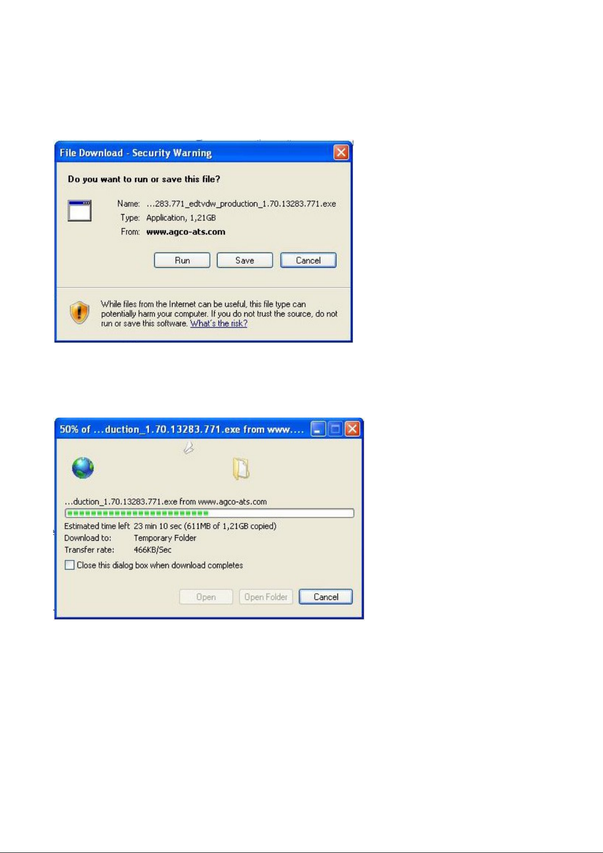
FIG.49
Insert the EDT CD. Select Run.
FIG.50
This screen will be displayed as the file is downloaded.
29
Page 30
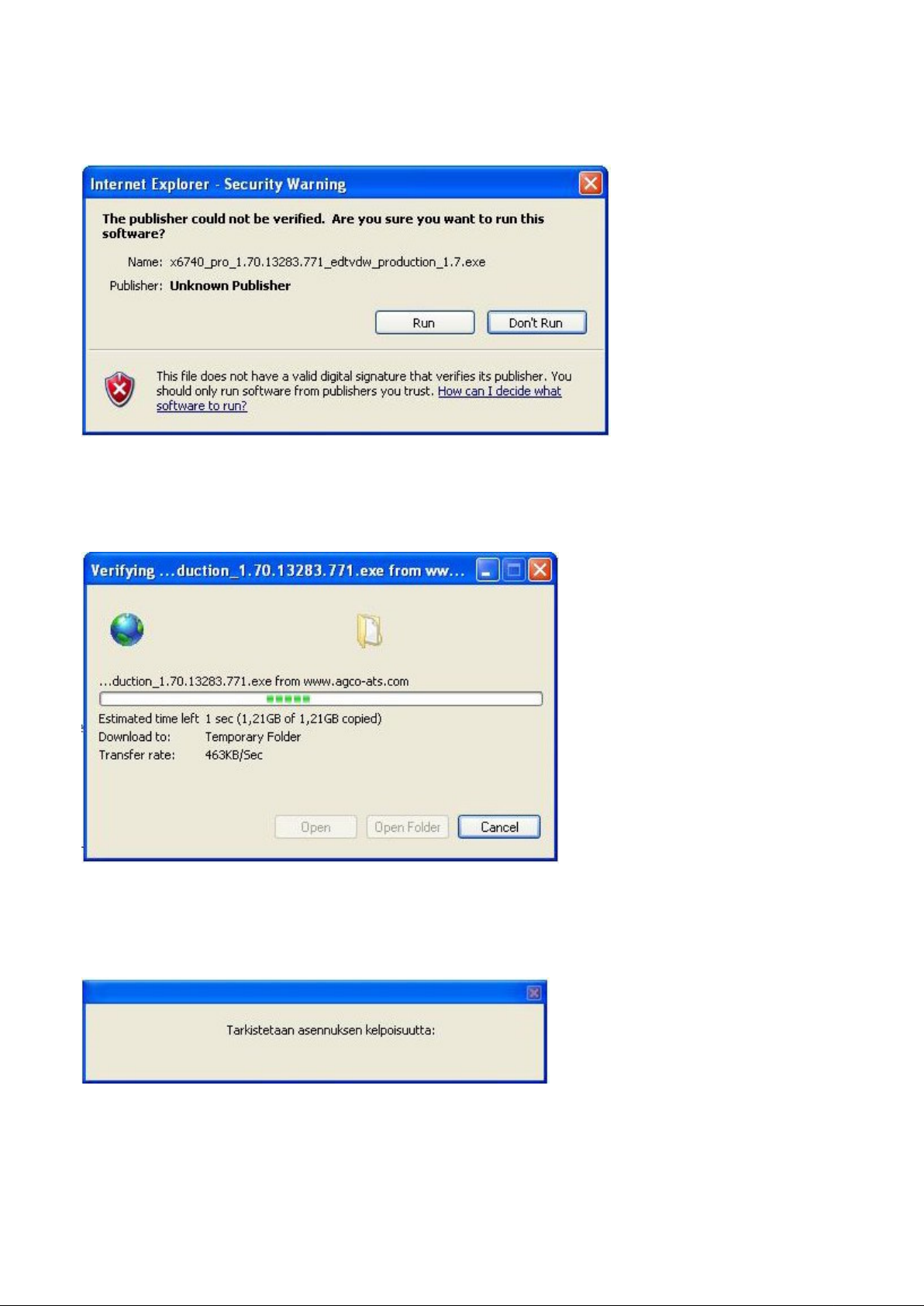
FIG.51
Select Run.
FIG.52
Windows Installer is verifying the data to your computer.
FIG.53
This dialog will appear when the computer is initializing the installation.
30
Page 31
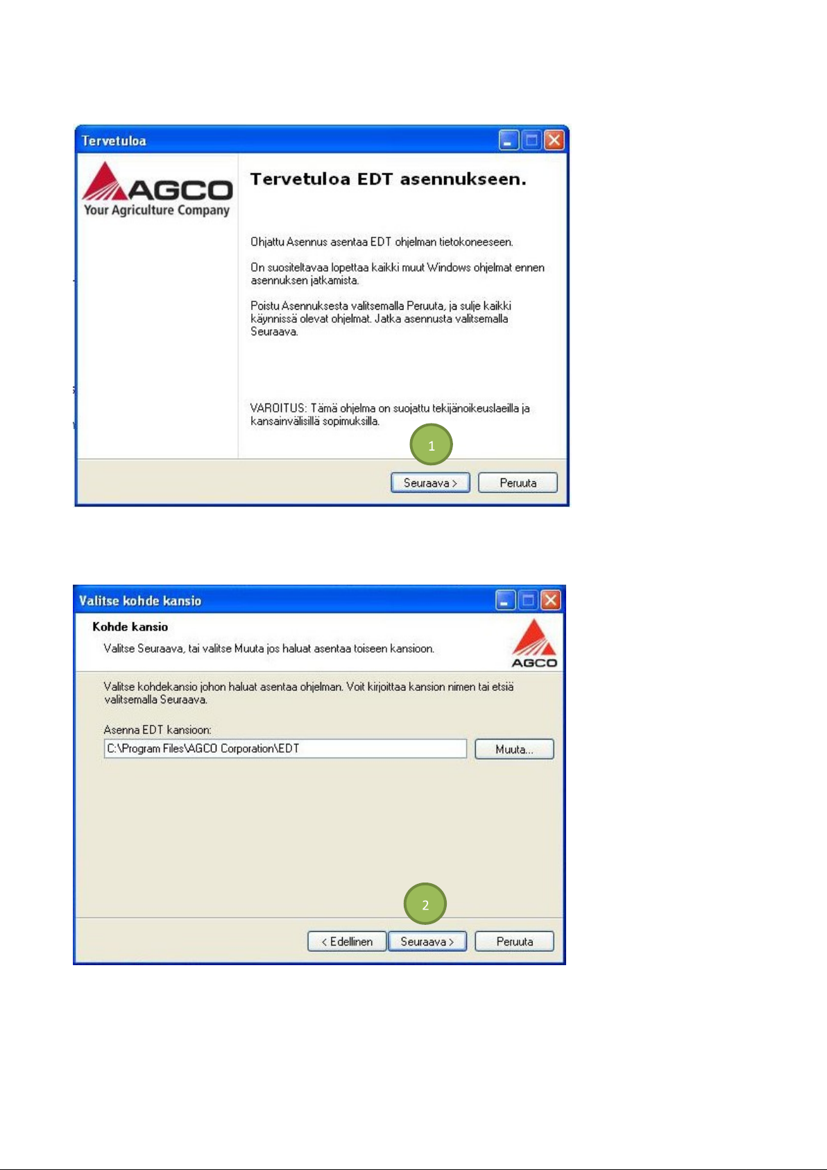
FIG.54
Shut down all windows programs before continue with EDT install. Select Next (1) to continue.
FIG.55
This dialog ask you to select the folder where to install the EDT program. Select Next (2) to continue.
31
Page 32
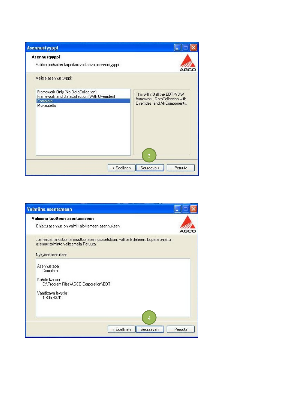
FIG.56
This dialog ask you to select the installation type of the EDT program. Select Next (3) to continue.
FIG.57
Ready to install. Select Next (4).
32
Page 33
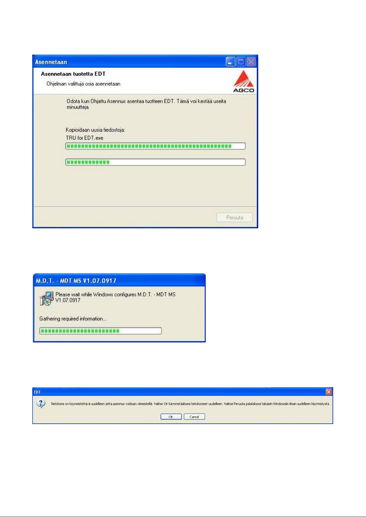
FIG.59
FIG.58
Installation of the EDT program. Do not cancel.
There will be some add-on configuration settings.
FIG.60
After software installation is complete, restart your computer. Select OK.
Remember to connect the EDT to the internet to install software updates.
33
Page 34

USING A PRINTER
The EDT runs on a standard Windows® 7 operating system and can be used for printing.
Printers (and faxing) can be set up by selecting Start then Devices and Printers. Refer to the printer user's manual for
configuration steps.
NON-AGCO APPROVED SOFTWARE
Non-AGCO approved software can be loaded on the diagnostic terminal. The system is not a locked unit. It is
STRONGLY RECOMMENDED that the dealer NOT install any unauthorized software to the terminal as many software
packages can introduce viruses, or errors in the tool operation which can lead to unnecessary tool downtime.
34
Page 35
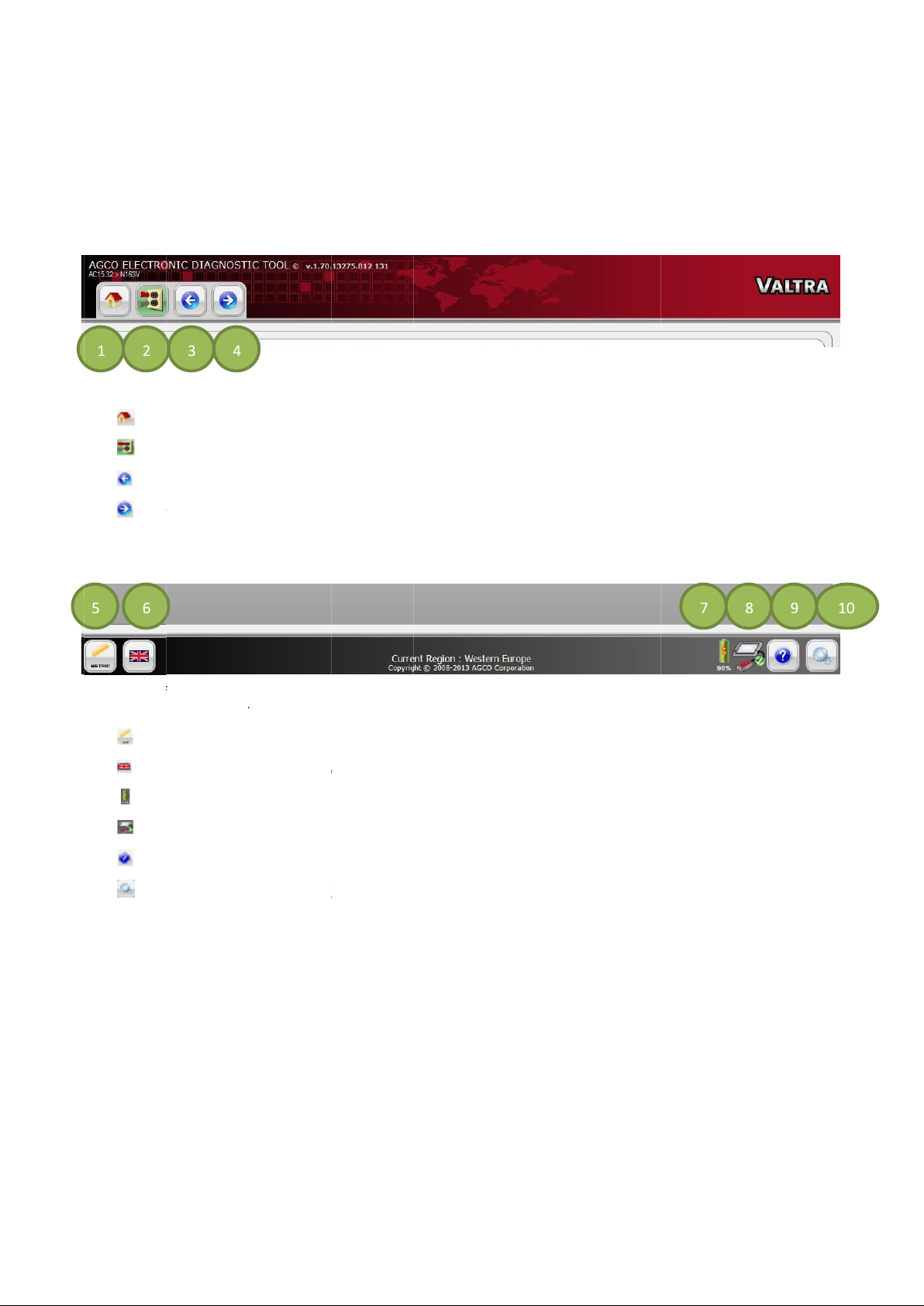
GETTING STARTED
FIG.61
(1)
(2)
(3)
(4)
FIG.62
also contains a graphical representation of CAN
(5)
(6)
(7)
(8)
(9)
(10)
On the header of all pages, icon controls are available.
Home page (s
CAN Connection page (see
Go back to previous page
Go forward to next page. This is only available if the Go back navigation icon has been used.
The footer of
Unit Selection (see
Language Selection (see
Battery Meter
CAN
p (see
Utilities (see
ee all pages contains
shows status of the battery at all times.
USB Presence icon (see
Help on page 36)
Utilities on page 39)
Home Page on 37)
Diagnostic Connection Selection on page 49)
Unit Selection on page 37)
Language Selection on page 38)
OPERATION
Unit Selection
USB Presence.
USB Presence on page 38)
Language Selection
, and
icons. The footer
35
Hel
,
-
-
-
CAN-
, Help
Utilities
Page 36
36
Help
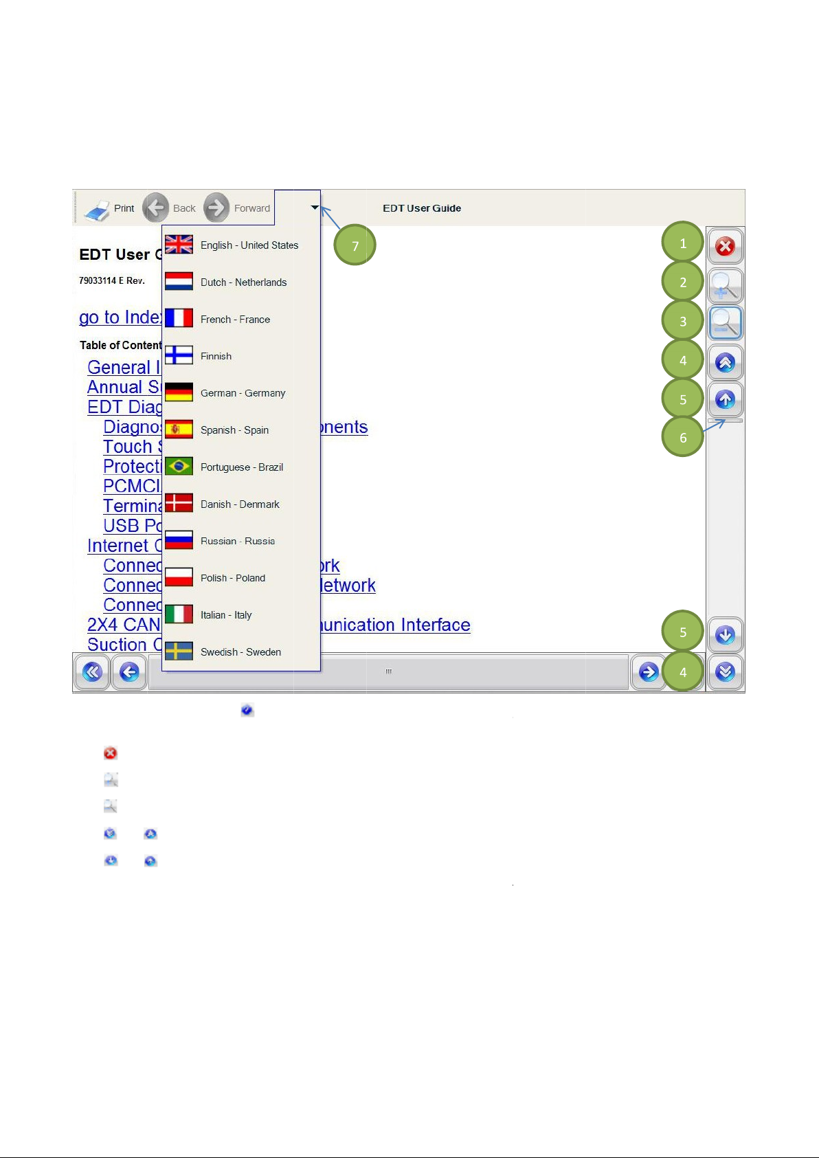
FIG.63
of the user guide, or
(1)
(2)
(3)
(4)
(5)
(6)
(7) Select the
Close the EDT User Guide.
Zoom in
Zoom out
Grab and slide the scroll slider
To change the language of the EDT User Guide, select the appropriate language.
icon
navigate through the user guide using the vertical scrollbar.
Select to scroll one page at a time.
Select to scroll one line at a time.
to display the EDT User Guide. Use the links (underlined text) to go to a specific part
up and down to scroll to different parts of the user guide.
or
or
Help
Page 37
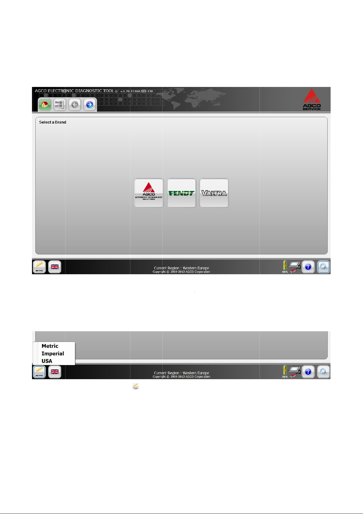
Home Page
After starting up the EDT, the Home Page will be displayed.
Connect the EDT to the
FIG.64
NOTE:
Unit Selection
At any time while using the EDT, the user can switch between unit systems.
FIG.65
NOTE: Metric is the defa
The unit options available are:
• • • The available brands will be available on the Home Page. Select a brand to select a vehicle for diagnosis.
The brands displayed on this screen will only be the brands associated with your Dealer code.
Select the
machine after the application is loaded.
Unit Selection
ult unit.
icon
to open a menu with the available unit systems. Select the appropriate unit.
37
Metric
Imperial
USA
Page 38
38
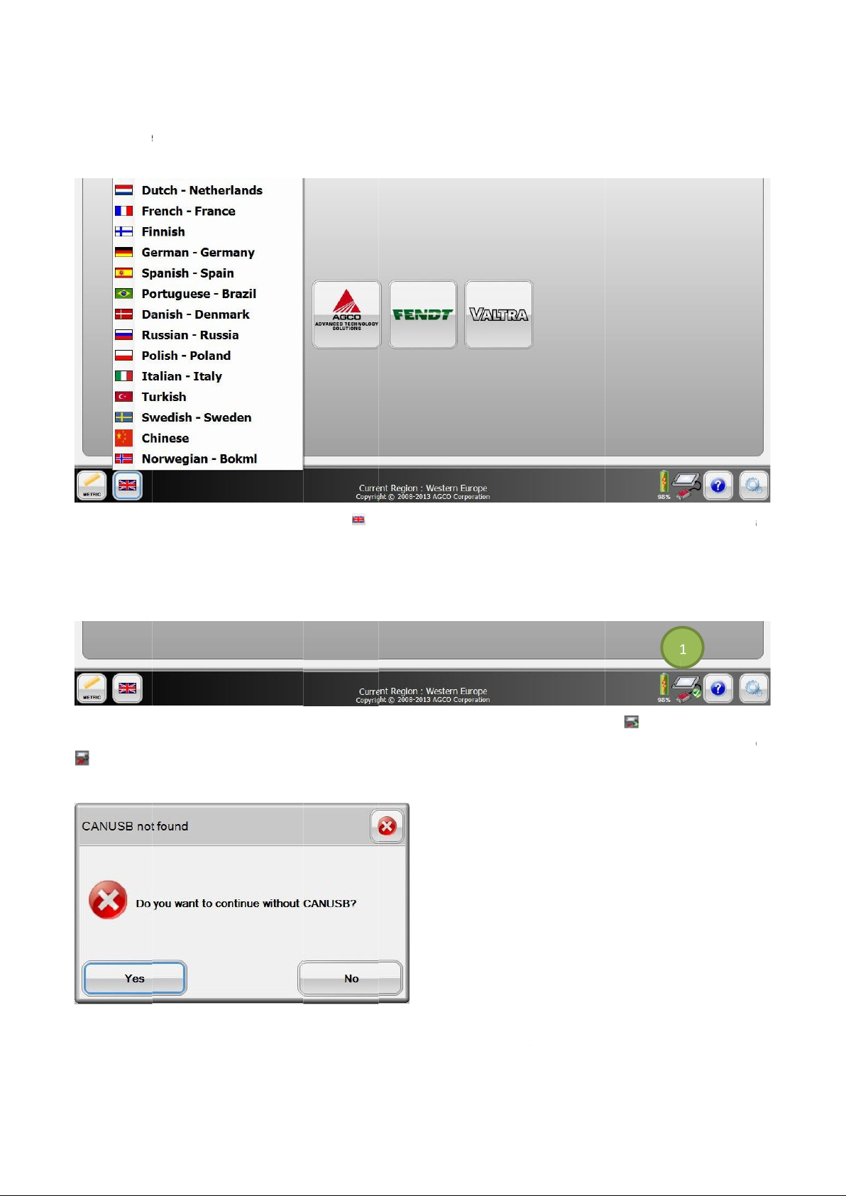
Language Selection
At any time while using the EDT, the user can switch between languages.
FIG.66
language.
CAN
FIG.67
the green check
FIG.68
Select the
Select the
NOTE:
USB Presence
If the CAN
will display with a red circle and slash (1) on the EDT screens.
If the CAN
Yes
Language Selection
English is the default language.
USB is plugged into the system where EDT is running, the CAN
mark (1). This means the CAN
USB is not connected, a message box will appear when the EDT application
icon to start EDT without CAN
to open a menu with the availab
USB is present. If the CAN
USB and the
icon to stop opening the EDT.
USB is not connected, the CAN
le languages. Select the preferred
USB icon
will be displayed with
is started.
USB icon
icon
-
-
-
-
-
-
-
-
No
Page 39
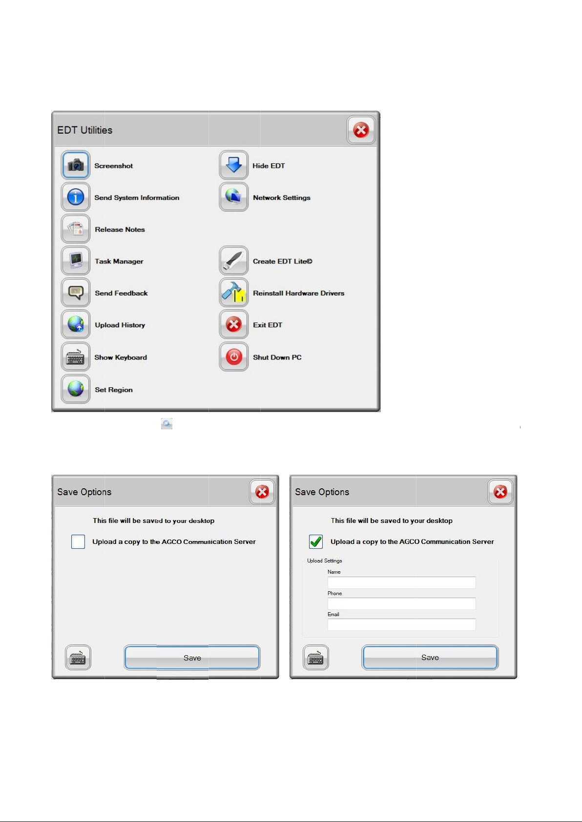
Utilities
FIG.69
operations of
Screenshot
FIG.70 & 71
saved to the desktop. If selecting to upload to the AGCO Communication Server, fill in the necess
to submit the image. Select
Utilities
icon
In the box that appears, specify if the image will be uploaded to the AGCO Communication server or just
EDT Utilities on page 22)
will guide the user through some of the more common
ary details to be able
39 40
The
(see
the tool.
Save.
Page 40
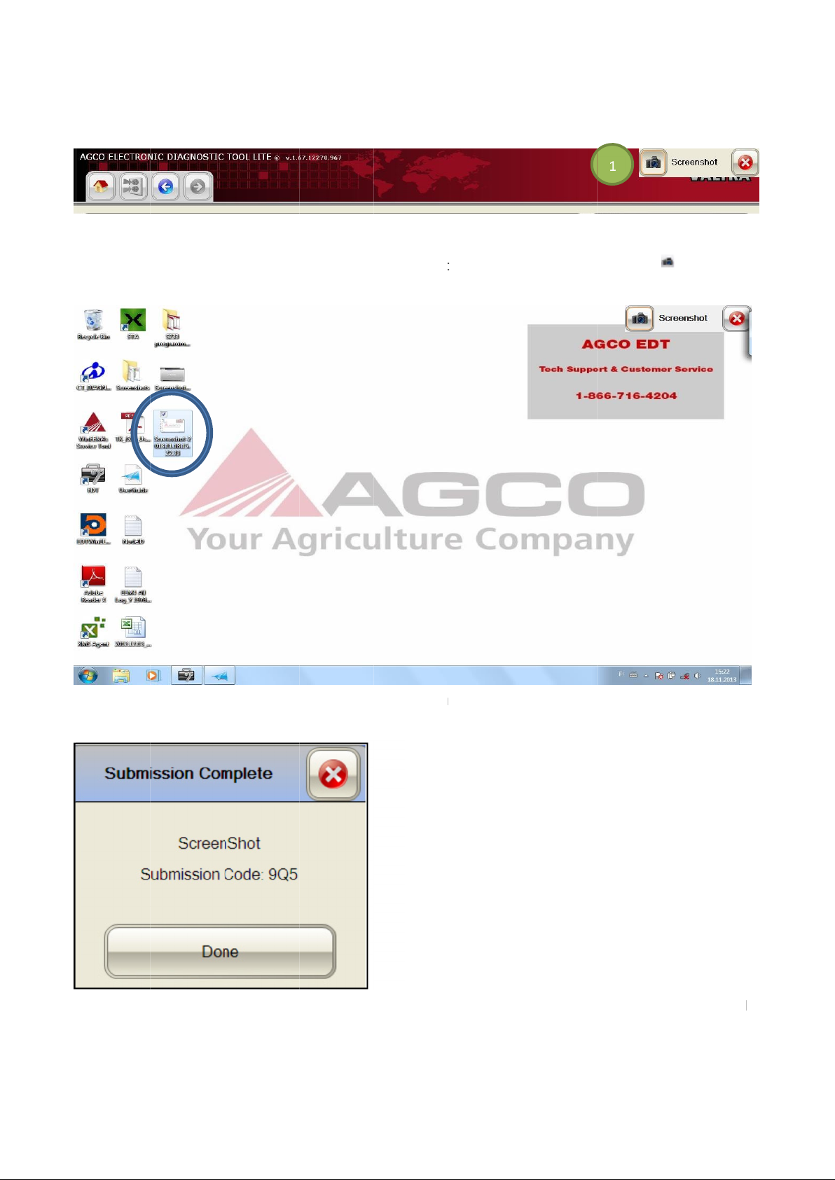
FIG.72
display in front of the EDT and can capture any aspect of the EDT functional
unresponsive. To capture an image, go to the desired section of the EDT and select the Camera icon
FIG.73
FIG.74
displayed. The Submission Code can be used by a support person to retrieve the screenshot from the server from any
PC connected to the internet. If the EDT cannot connect to the in
An additional control icon will be added to the top right
A screen shot is taken and copied to the desktop with a time stamp.
If uploading a copy to the
AGCO Communication Server, and you are online, a submission dialog will be
ternet the upload will be queued for a later time.
hand corner of the screen (1). This control icon will
ity, even if the EDT becomes locked or
-
.
Page 41
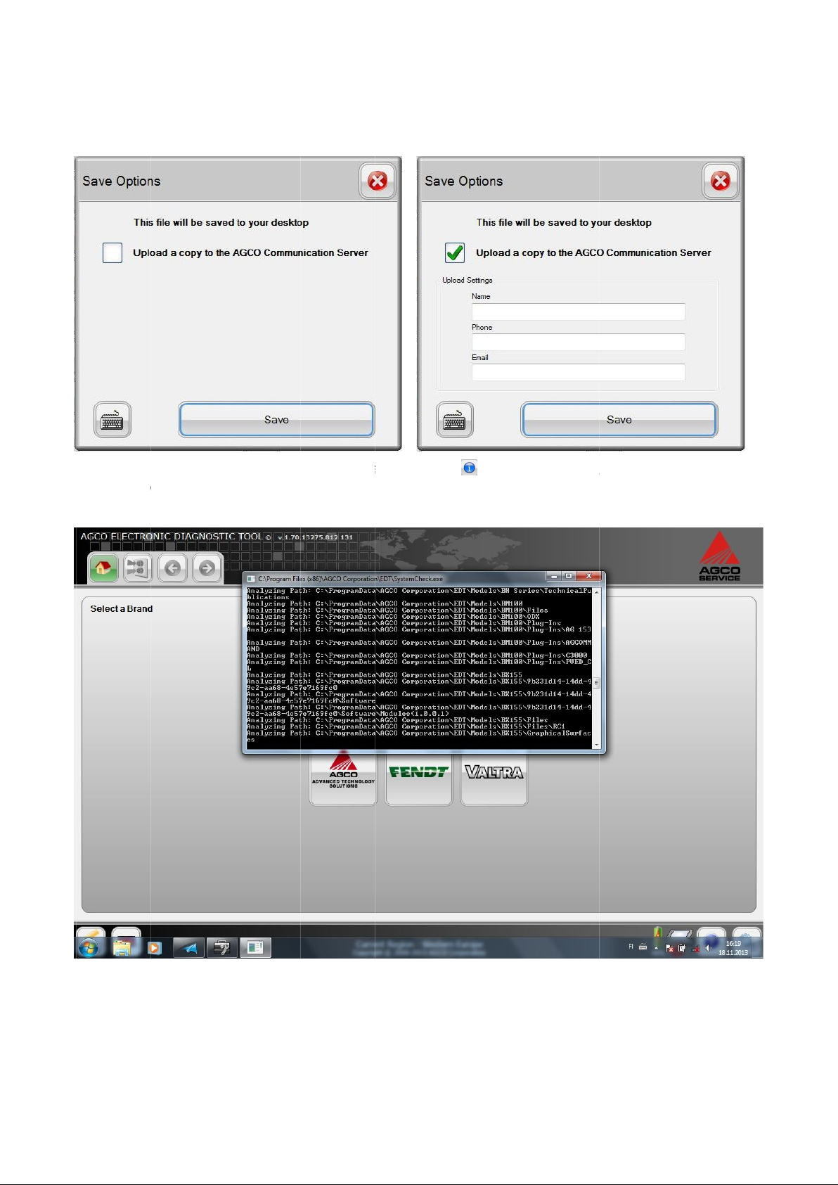
Send System Information
FIG.75 & 76
Options dialog as in the Screenshot u
FIG.77
whether the EDT is open or closed.
Select Save to begin the
After selecting the Send System Information icon
tility will be available.
System Check process. This is a stand alone process that will run in the background
from the Utilities main screen, the same Save
41
Page 42
42
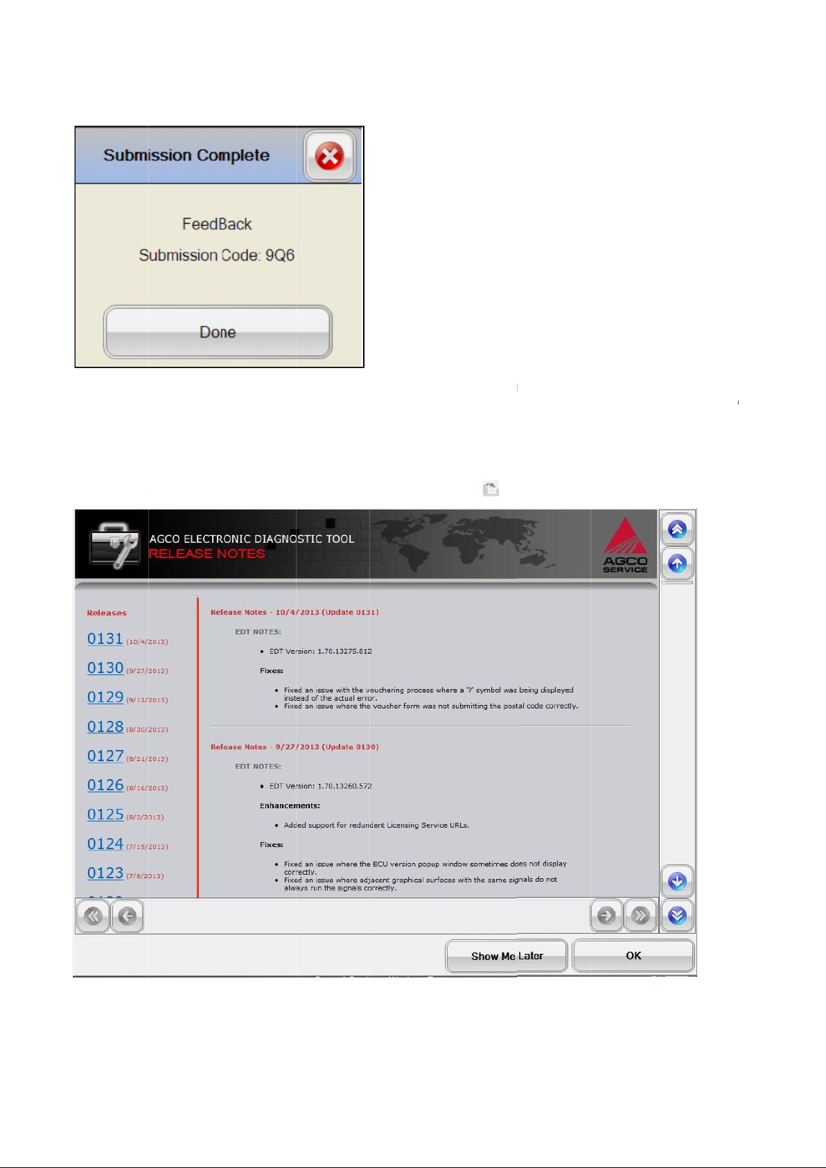
FIG.78
the AGCO Communication Server option was selected, a submission code will be returned after the file has been
uploaded.
Release Notes
Release notes are available at any time
FIG.79
The check takes several minutes to complete. A co
Release Notes screen.
Release Notes
py will be placed on the desktop and if the Upload a copy to
using the
icon .
Page 43
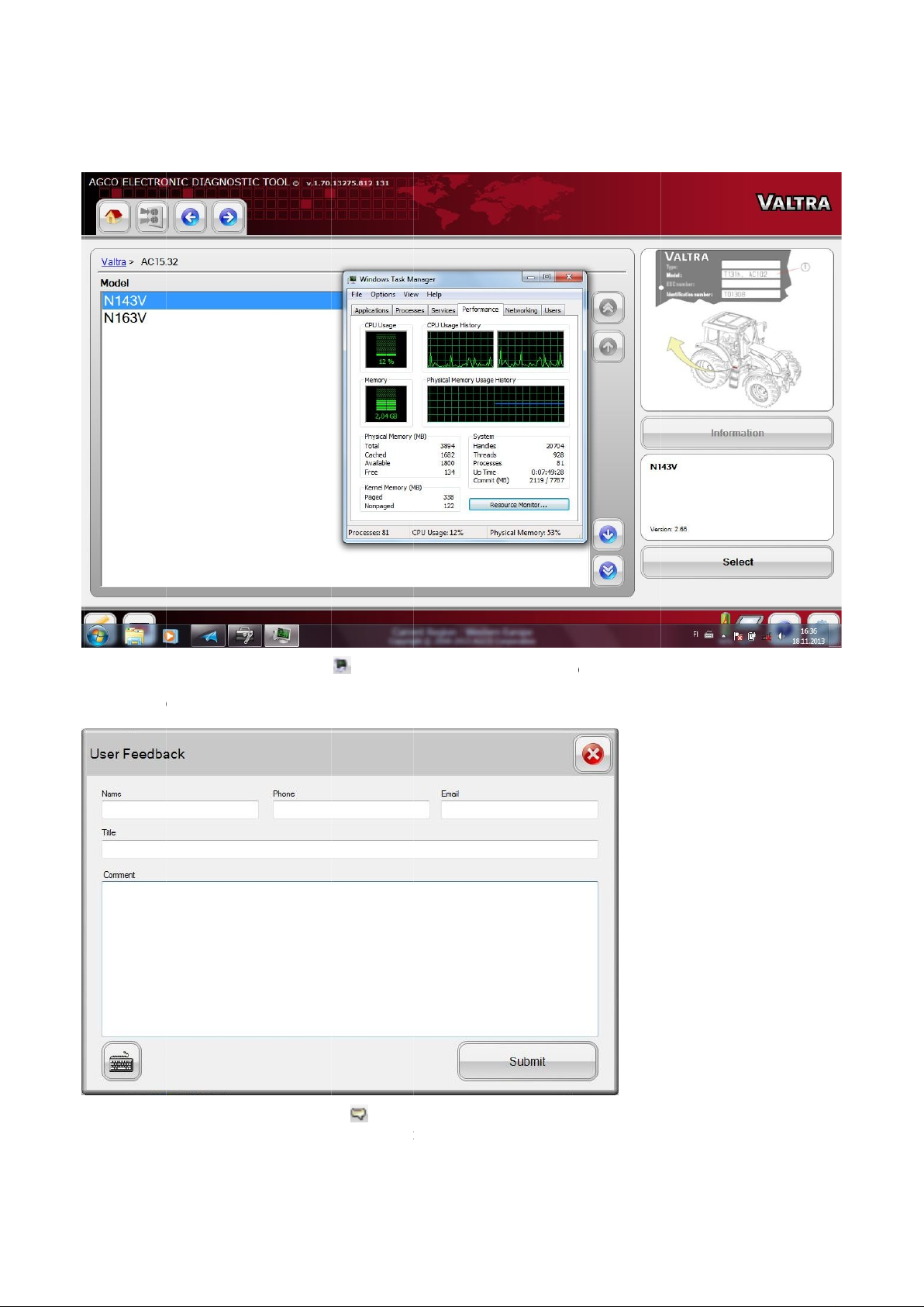
Task Manager
FIG.80
Send
FIG.81
group, fill out your contact information and comments, then select the SUBMIT icon.
Select on
Feedback
Select the
Task Manager
Send Feedba
icon
icon to load the Windows
to load the User Feedback form. To send comments to the EDT support
Task Manager.
43
®
ck
Page 44
44
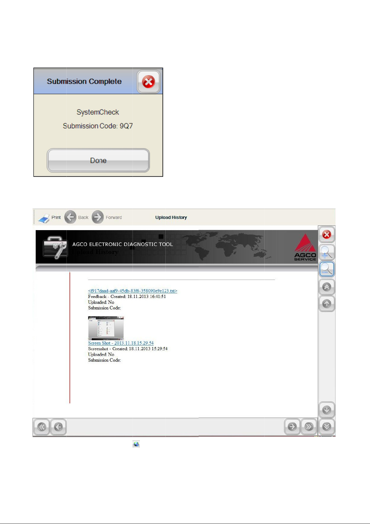
FIG.82
View
FIG.83
The Upload History log details all content that has been uploaded. To review a file, select on the desired file.
A submission code will be returned after the file has been uploaded.
Uploads
Select the Upload History icon
will load the Upload History log.
Page 45
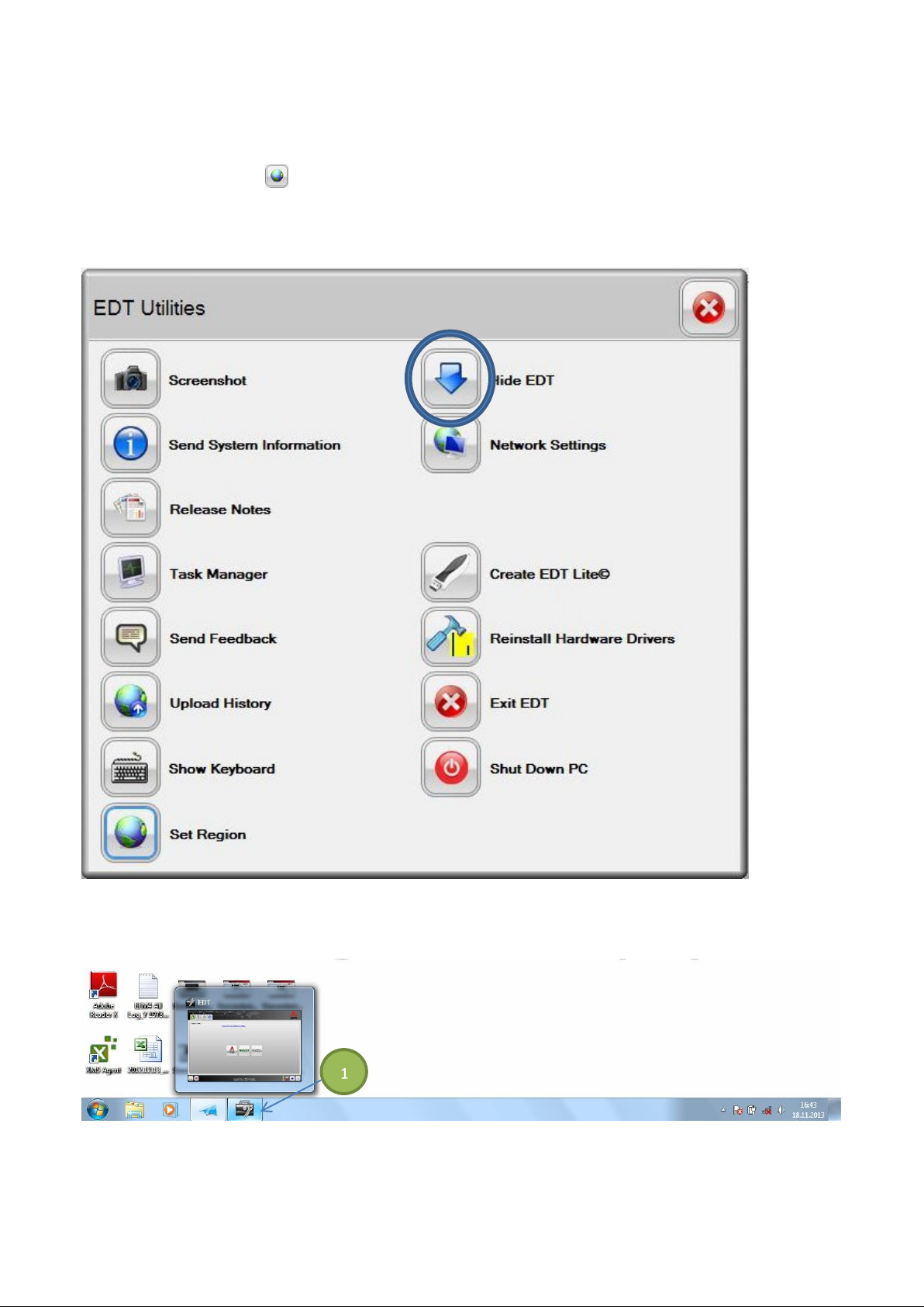
Set Region
Select the Set Region icon to set the desired region. See Set Region on pages 21 and 22 for more information.
Hide EDT
FIG.84 To minimize EDT down to the task bar and work directly with the operating system, select the Hide EDT icon
from the Utilities main screen.
FIG.85 To return the EDT to the original size, select the EDT icon (1) in the task bar.
45
Page 46
46
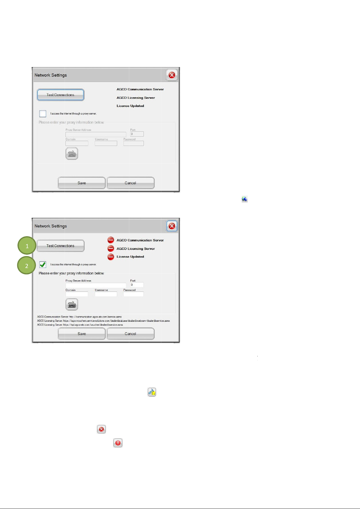
Network Settings
FIG.86
FIG.87
next to
Reinstall Hardware Driver
Select the
Exit EDT and
Select the
Select the
To setup and test the network connection, select the
t the current connection by selecting the Test Connections icon (1).
access the internet through a proxy server
Reinstall Hardware Drivers
Exit EDT
Shut Down PC
Shut Down PC
to close the EDT.
to shut down the PC.
to reinstall hardware drivers of
Network Setting
option. Enter the appropriate proxy information.
If using a proxy server, select the box (2)
the EDT.
Tes
I
icon .
s
icon
icon
icon
Page 47
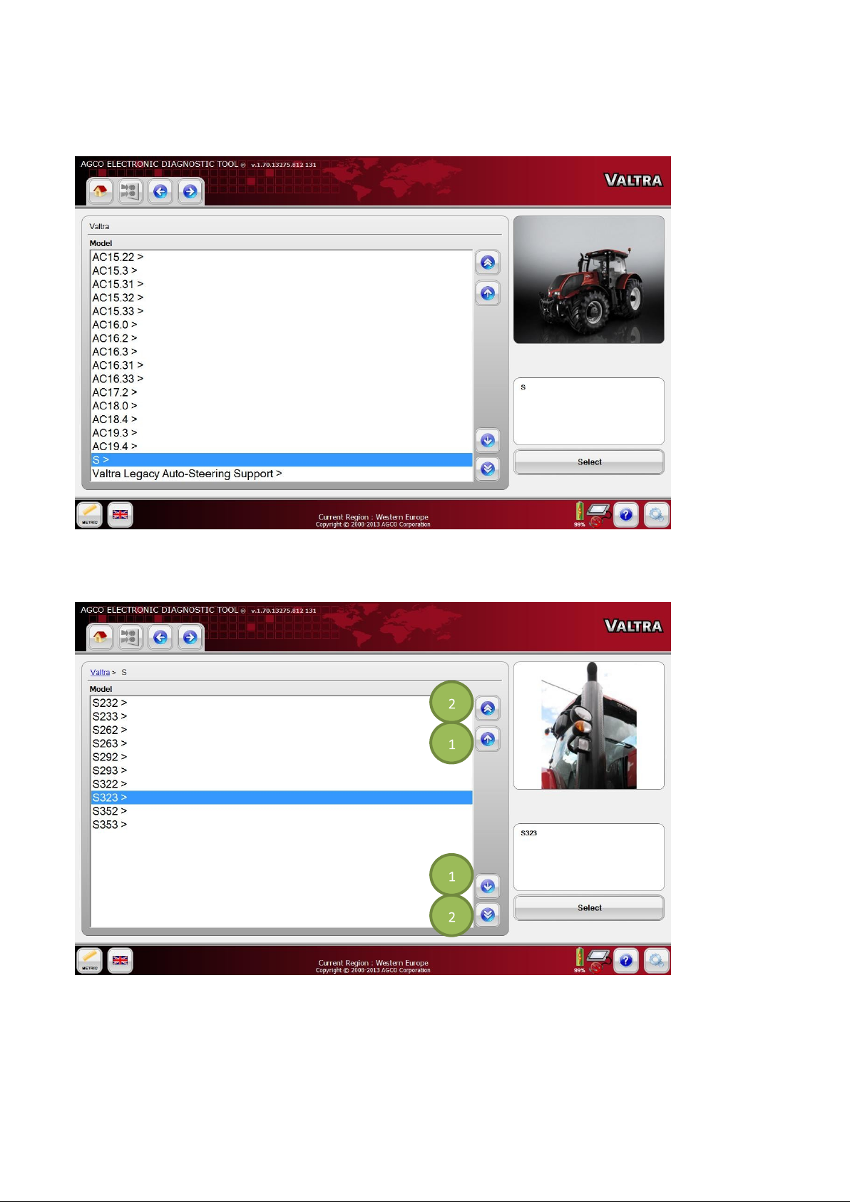
VEHICLE SELECTION
FIG.88 After the brand has been selected from the Home Page, all vehicles supported by EDT for the brand will be
listed. All Suolahti produced vehicles are based on the Automation Configuration (AC) numbers.
FIG.89 To select a model, highlight the model using the up and down arrows at the right, or use the touch screen. Then
press the Select icon.
(1) Scroll through the models one by one.
(2) Scroll to the top or bottom of the list. If more than one page of models is available, scroll page by page.
47
Page 48
48
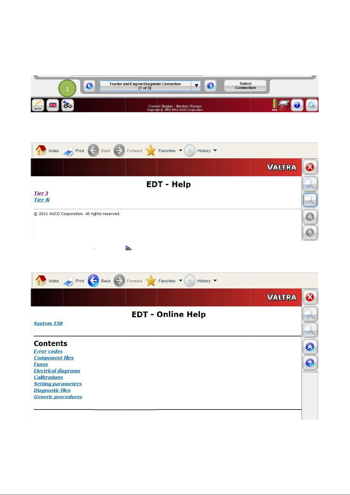
Whole Machine Help Files
FIG.90
the diagnostic section by selecting the Information icon (1) that has relocate
FIG.91
be the selection option description.
FIG.92
electrical schematics and component locations.
Once the vehicle has been loaded in the EDT the machine specific information can be viewed any time during
Selecting the Information icon
Vehicle specific help can contain infor
will load vehicle specific help. After selecting a machine level help, there will
mation including quick links to fault trees, calibrations, diagnostic files,
d to the bottom left
hand corner of the EDT.
-
Page 49
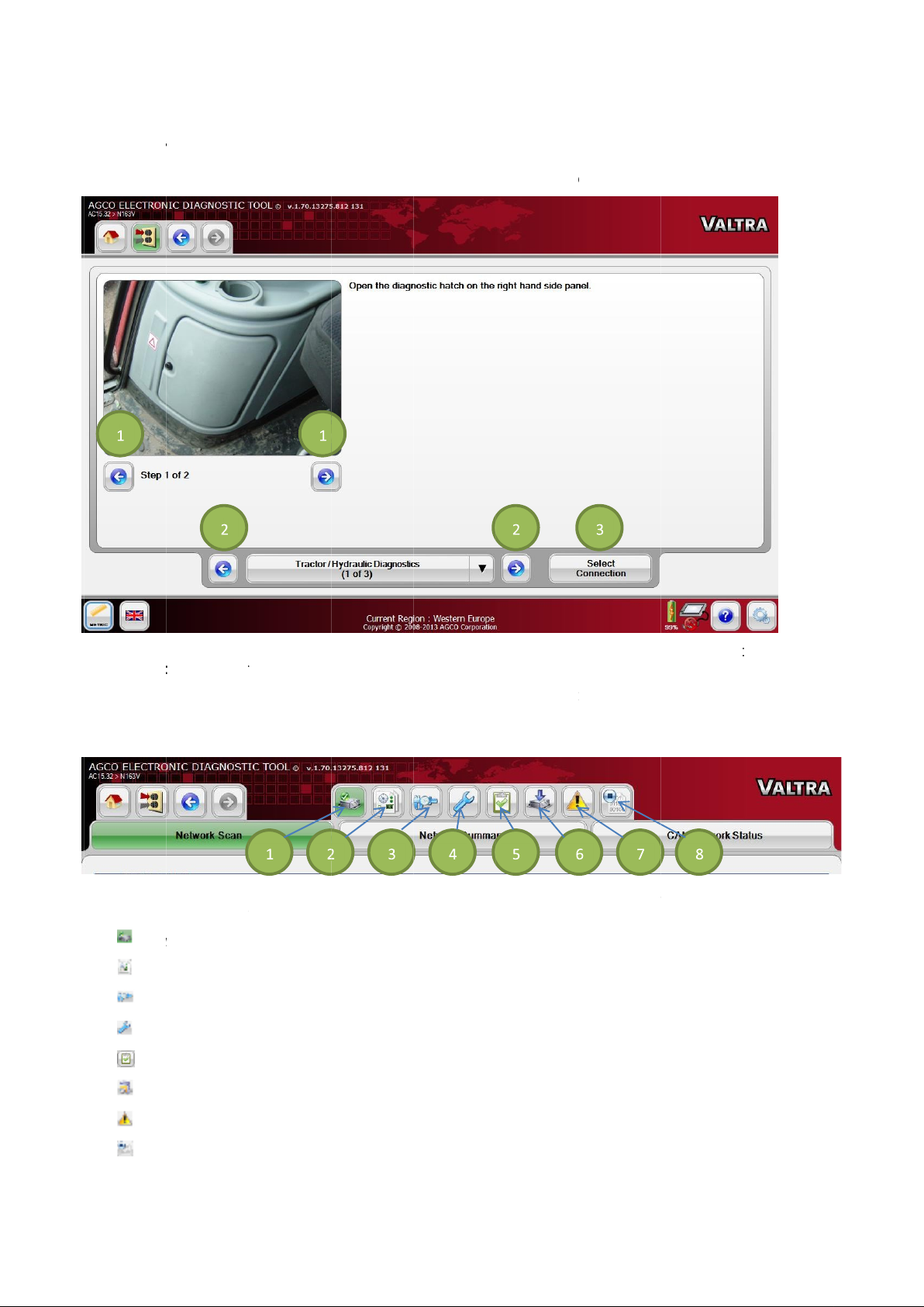
DIAGNOSTIC CONNECTIO
After the desired model is selected, the screen will display
FIG.93
using the
NOTE:
the vehicle’s diagnostic port.
FIG.94
until after a vehicle has been selected. The selected icon will be highlighted in green.
(1)
(2)
(3)
(4)
(5)
(6)
(7)
(8) Scroll through the steps (1) for further instruction on the connection points. Navigate through the connections
left
The EDT can be ON when connecting to a vehicle. The vehicle must be OFF during connection of the EDT to
A group of navigation icons appears after the Diagnostics Connection page
Network Scan (
Diagnostic by Function
Calibration
Configuration
Diagnostic Test
Software Flash
Diagnostic Trouble Co
CAN Trace
arrow icons (2). Select the desired connection by selecting the
Set by default after the vehicle connection point is selected)
N SELECTION
the available connections.
Select Connect
. These options are not available
49
and right
ion icon (3).
des
Page 50
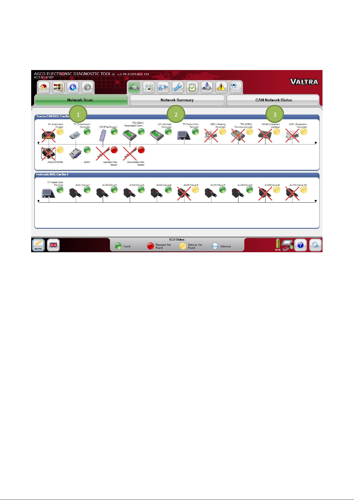
NETWORK SCAN
FIG.95 The Network Scan page has a tab selector to show Network Scan (1), Network Summary (2) and CAN
Network Status (3).
Network Scan shows all the available ECUs on the network channel and the connection status of each.
• Green LED - ECU is available
• Red LED - ECU is absent
• Yellow LED - ECU is optional
• White LED - ECU is unknown
Select any ECU to display the current hardware and software version loaded on that ECU.
50
Page 51
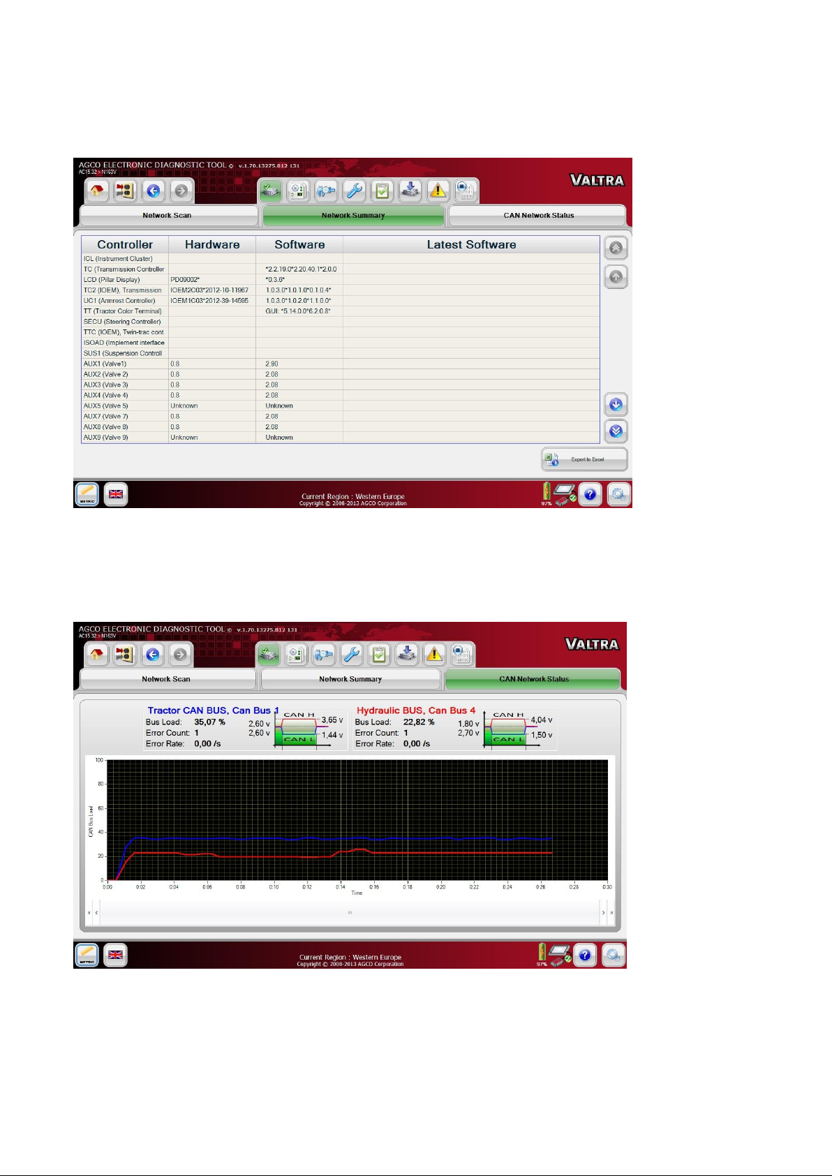
Network Summary
FIG.96 Network Summary shows a table of control units scanned from the CAN Bus.
The hardware and software will also be displayed on this page if the information is available.
CAN Network Status
FIG.97 CAN Network Status shows a graph plotted between the CAN Bus Load in Percentage and Time. The Error
Count will also be displayed on this page.
The screen will display green and red lines showing normal and overload levels of the CAN network activity.
51
Page 52
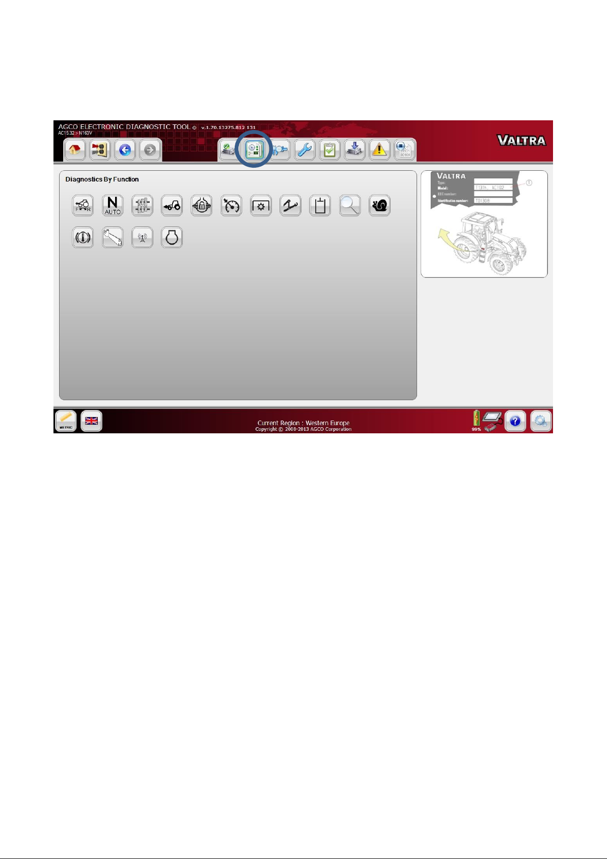
DIAGNOSTICS BY FUNCTION
FIG.98 Diagnostics by Function contains icon controls for the available functions defined for the vehicle. Select a
function to perform a diagnostic review of a specific vehicle system.
NOTE: Consult the specific machine’s service manual for information on how to use the EDT diagnostic functions for
the machine.
NOTE: The following pages describing Graphical Diagnostics, Diagnostics Summary, and Diagnostics Reporting are
all sub-functions of Diagnostics by Function.
52
Page 53
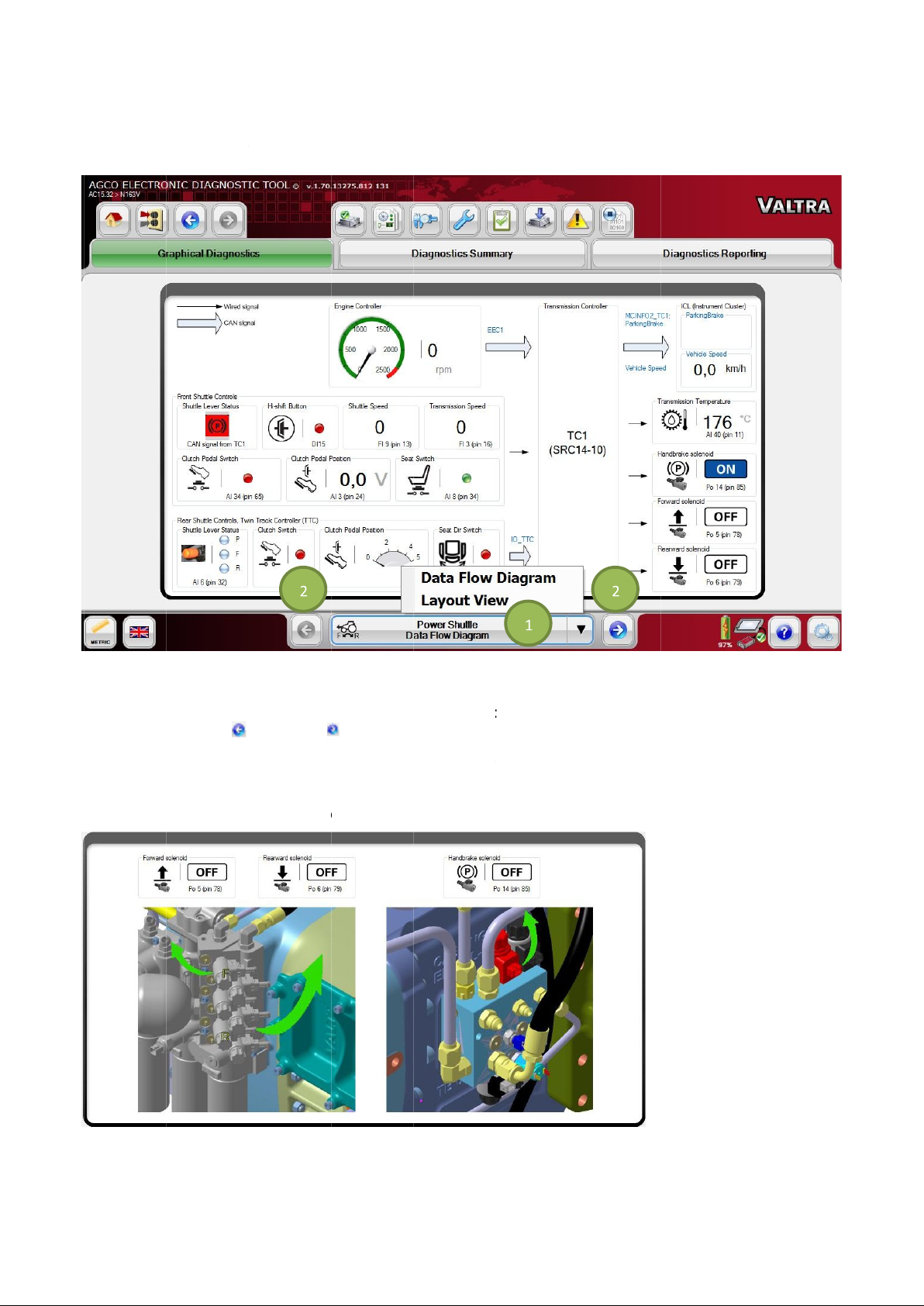
Graphical
FIG.99
available graphical surfaces for the selected function will be available.
Select the icon (1) at the bottom center of
surfaces using the
NOTE:
Graphical Diagnostics Graphic Screen
FIG.100
Graphics Diagnostics
See the machine service manual for the information on how to use the diagnostic surfaces of the EDT.
Some of the screens in
Diagnostics
contains the graphical surface of the desired function to be diagnosed. A list of
Graphical Diagnostics
Graphical
arrow icons (2) to select the desired surface.
Diagnostics
will show a location of the sensor or switch on the machine.
to show the list, or navigate through the graphical
53
left
and right
Page 54
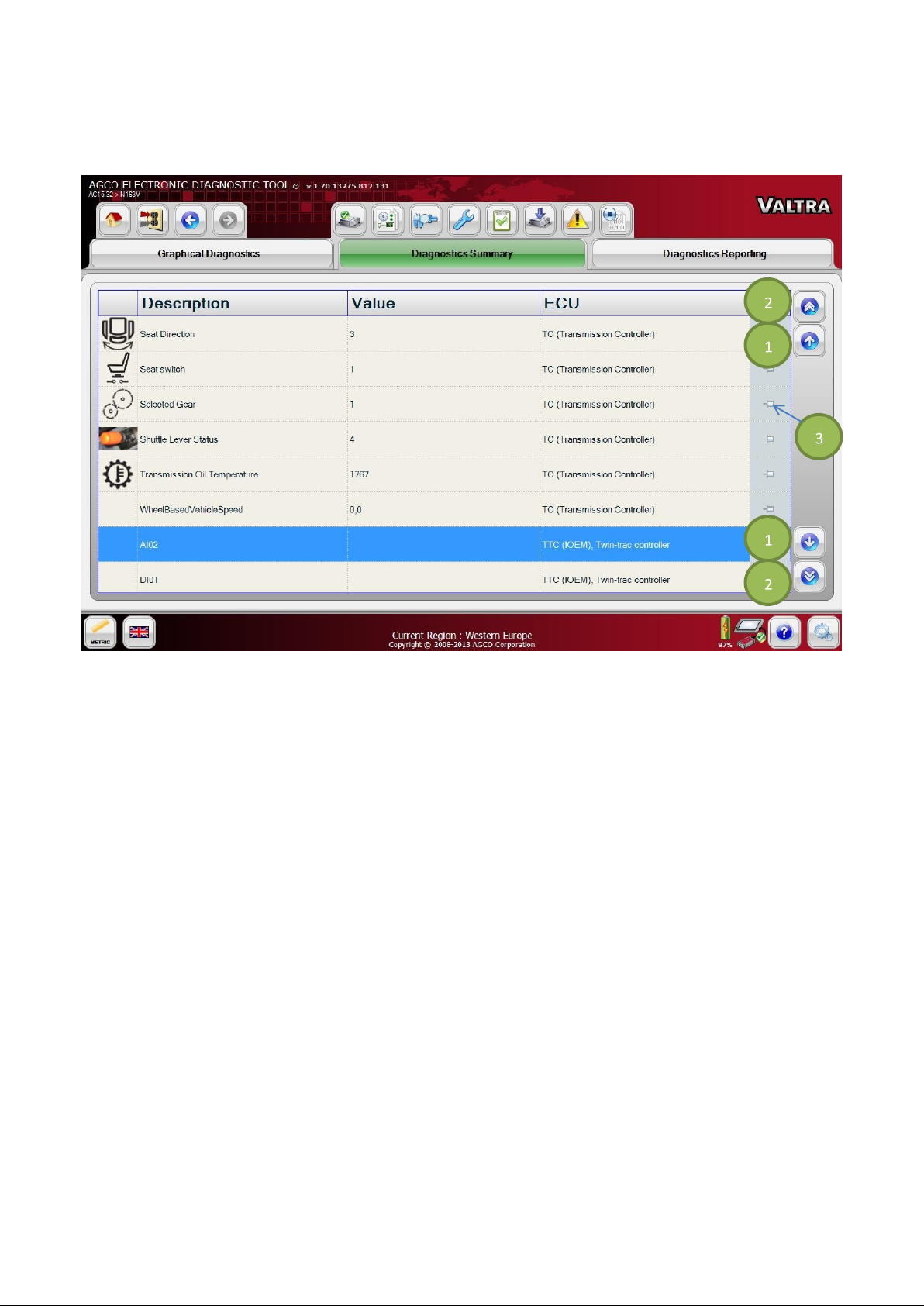
Diagnostics Summary
FIG.101 Diagnostics Summary shows the signal icon, signal Description, signal Value, and ECU name in a grid view.
Select the single arrow icons (1) to scroll through each row.
Select the double arrow icons (2) to scroll through each page.
If you want a specific row to be at the top, select the pin icon (3) to the right of the desired row.
54
Page 55
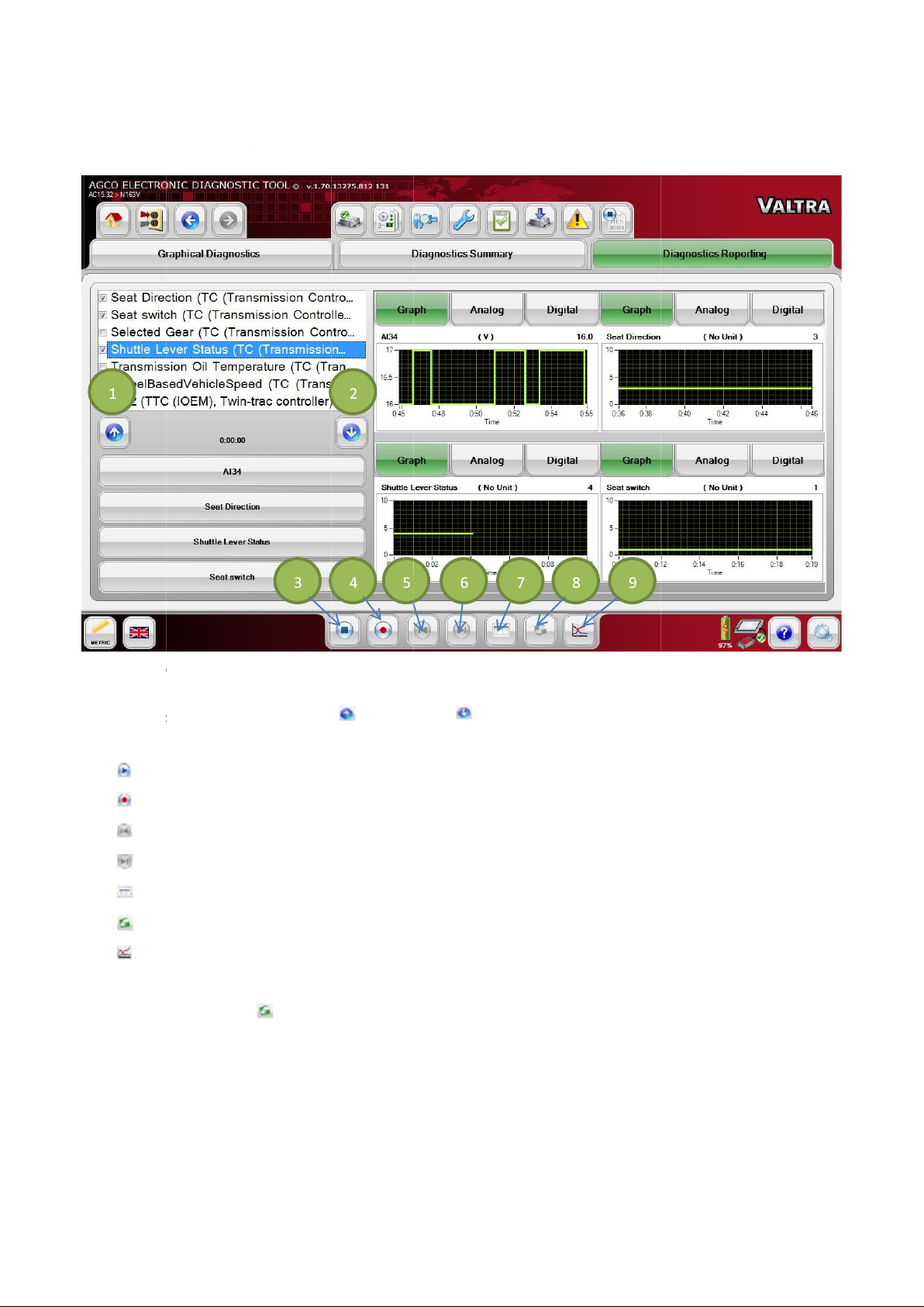
Diagnostics Reporting
FIG.102
against time. A maximum of four signals can be selected at a time.
Select the desired signal(s). Use the up
The following
(3)
(4)
(5)
(6)
(7)
(8)
(9)
Signals are recorded as an Excel file with a .csv extension.
Select the
Diagnostics Reporting
Stop / Play
Record
Rewind
Forward
View Signal Trace
Play Back
Plot Multiple Signals
Play Back
plotting selections are available:
icon
allows the opti
ay back recorded signals.
on to select or deselect the signals to be plotted as a wave form
(1) and down
(2) arrow icons to scroll through the selections.
55
to pl
Page 56
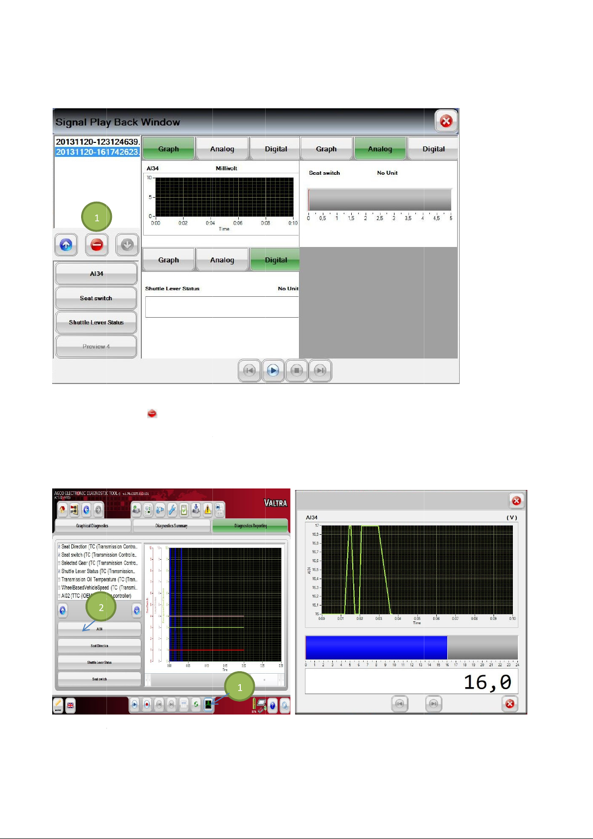
56 Diagnostics Reporting Signal Play Back Window
FIG.103
Select the
NOTE:
Diagnostics Reporting
FIG.104
back A preview of the selected signal(s) is available and can be viewed in graph, analog, or digital view.
Delete
Deleting a select
& 105
an individual recorded signal. Previewing of this signal is also available in graph, analog, or digital view.
ed file removes the file permanently from the storage location.
Multiple and
Select multiple signals (1) to preview selected signals in one graph. Select a
(1) to delete a file.
Individual Signal Preview
icon (2) to play
icon (2) to play
icon
signal
Page 57
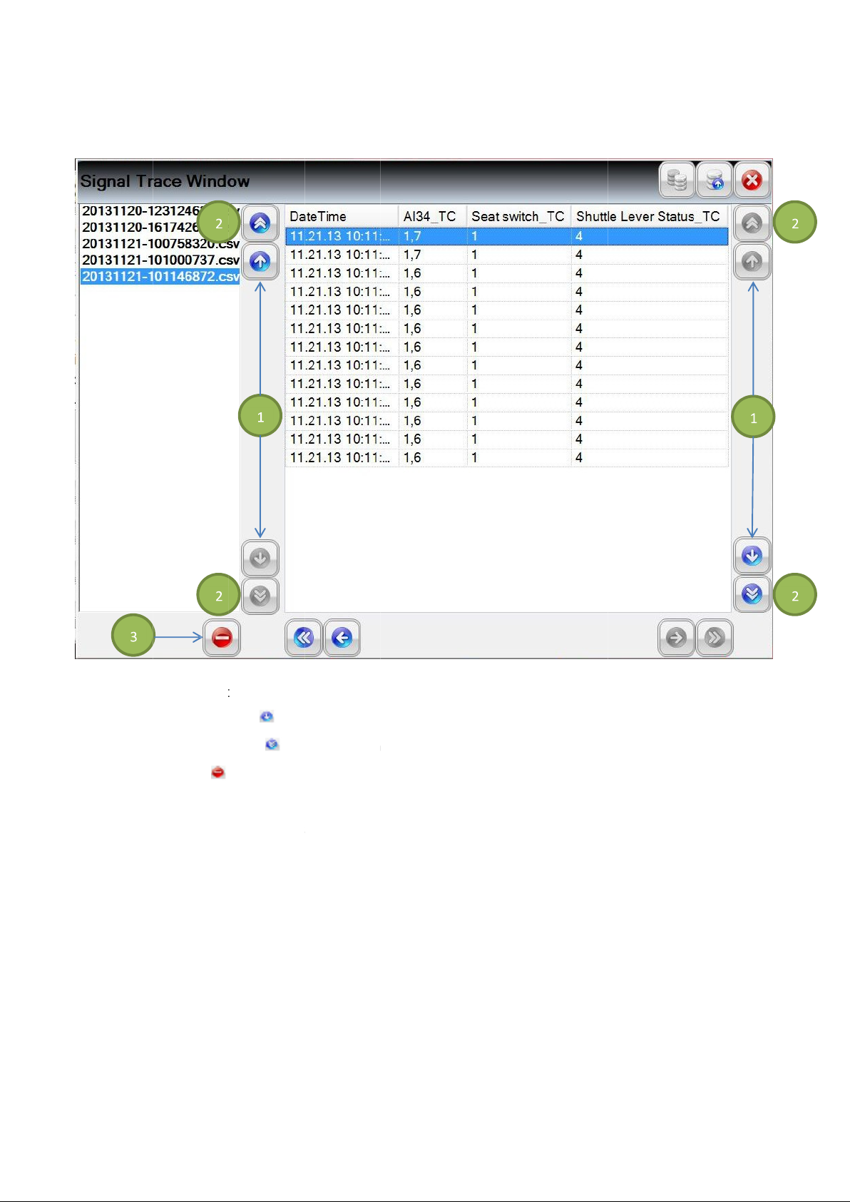
Diagnostics Reporting Signal Trace Window
FIG.1
the list shown, or change the selection of the file using the up and down icons.
Select the
Select the
Select the
NOTE:
Each recorded signal log with a .csv extension can be viewed in a grid layout. To
single arrow
double arrow
Del
Deleting a selected file removes the file permanently from the storage location.
icons
icons
(1) to scroll through each row.
(2) to scroll through the pages.
(3) to delete a file.
do so, select on a file from
57
06
ete icon
Page 58
58
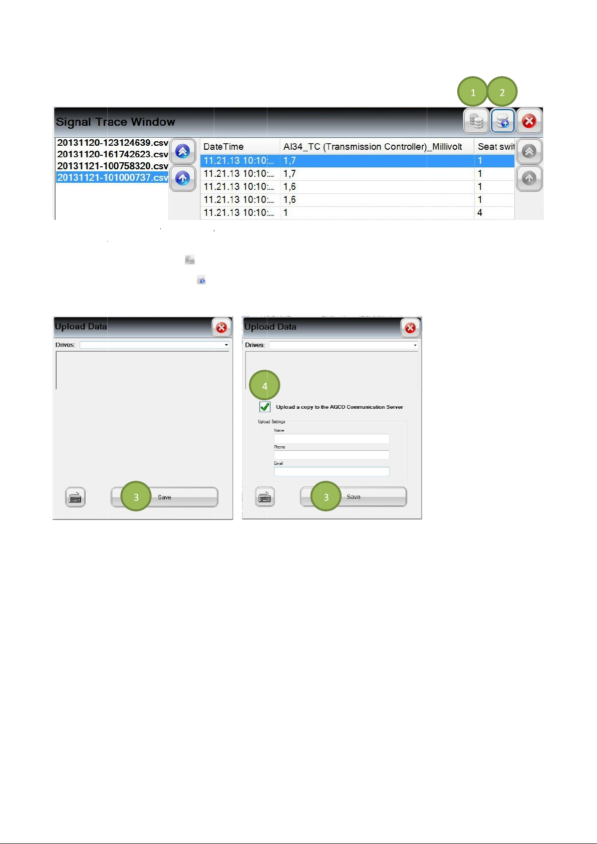
Diagnostics Reporting File Upload
FIG.1
remov
Select the
Select the
FIG.1
Select the
Specify
From the Signal Trace Window, either all files or a single file can be uploaded to a selected drive (fixed drive,
able drive, CD rom, etc.)
Copy All Files
Copy Single File
09
Save
if the files will be uploaded to the AGCO Communication Server (4).
In the pop up windows, select the desired drive.
(1) to upload all files.
(2) to upload a single file.
07
icon
icon
08 & 1
icon (3).
Page 59
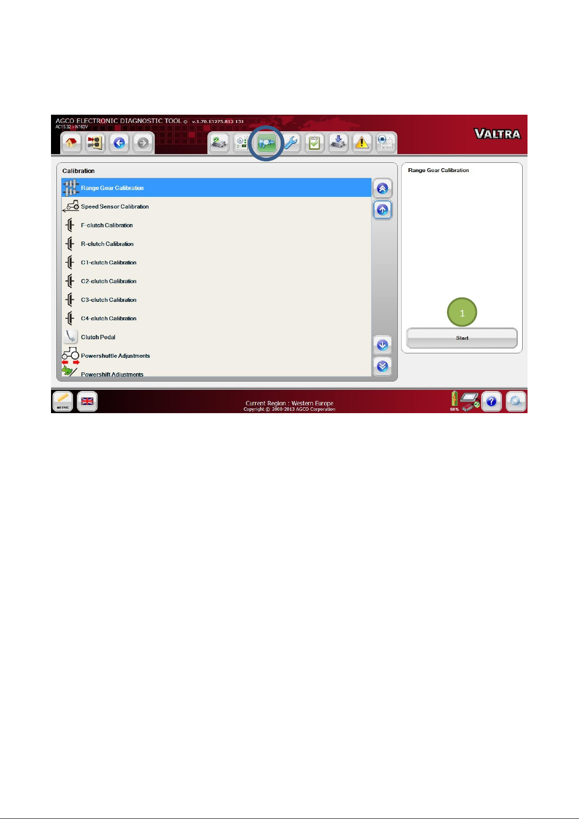
CALIBRATION
FIG.110 Go to the Calibration tab and select an item from the list. Press the Start icon (1) to run the Calibration script of
the selected item through a sequence of steps. Follow the instructions given by EDT.
Available calibrations for Valtra Suolahti vehicles vary depending of the tractor model:
- Main Gear Calibration (Versu / Direct / Hitech 5PS)
- Range Gear Calibration (Versu / Direct / Hitech 5PS)
- Hydrostatic Unit (Direct only)
- Speed Sensor Calibration
- F- clutch Calibration
- R-clutch Calibration
- C1-clutch Calibration (Versu / Hitech)
- C2-clutch Calibration (Versu / Hitech)
- C3-clutch Calibration (Versu / Hitech)
- C4-clutch Calibration (Versu / Hitech 5PS)
- Clutch Pedal Calibration
- Powershuttle Adjustments
- Powershift Adjustments (Versu / Hitech)
- Injector Calibration
NOTE: See the machine special instructions for the information on how to use the calibrations from Valtra Info.
59
Page 60
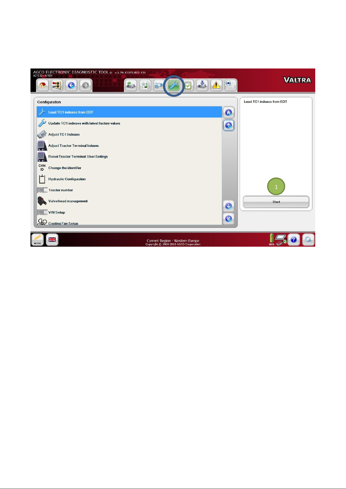
CONFIGURATION
FIG.111 Go to the Configuration tab and select an item from the list. Press the Start icon (1) to run the Configuration
script of the selected item through a sequence of steps. Follow the instructions given by EDT.
Available functions for Valtra Suolahti vehicles under the Configuration tab vary depending of the tractor model:
- Save TC1 indexes to EDT
- Load TC1 indexes to EDT
- Update TC1 indexes with latest factory values
- Adjust TC1 indexes
- Adjust Tractor Terminal Indexes
- Reset Tractor Terminal User Settings
- Change the identifier (CAN ID)
- Hydraulic Configuration
- Tractor number
- Valve head management
- VIN Setup
- Cooling Fan Setup
- Engine Service Parameter Configuration
- Use Engine Activation Code
- Bypass Specification Mismatch
NOTE: See the machine special instructions for the information on how to use these functions from Valtra Info.
60
Page 61
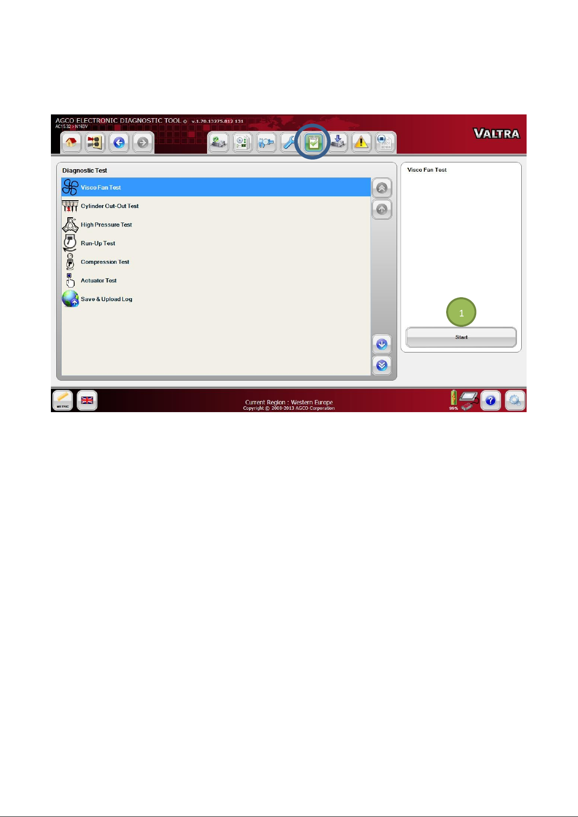
DIAGNOSTIC TEST
FIG.112 Go to the Diagnostic Test tab and select an item from the list. Press the Start icon (1) to run the Diagnostic
Test script of the selected item through a sequence of steps. Follow the instructions given by EDT.
Available diagnostic tests for Valtra Suolahti vehicles vary depending of the tractor model:
- Hydrostatic Unit Test (Direct only)
- Visco Fan Test
- Cylinder Cut-Out Test
- High Pressure Test
- Run-Up Test
- Compression Test
- Actuator Test
- Save & Upload Log
NOTE: See the machine special instructions for the information on how to use the diagnostic tests from Valtra Info.
61
Page 62
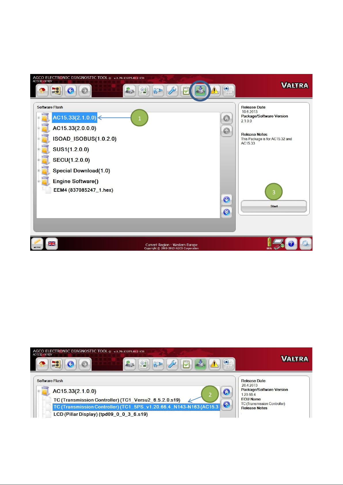
SOFTWARE FLASH
ECUs are updated using Flash downloads. This helps fix issues as well as roll out new or enhanced features.
FIG.113 Available software packages are listed under the Software Flash tab.
NOTE: Before flash download, make sure the diagnostic terminal is plugged into an AC power source.
IMPORTANT: Do not interrupt software download activity by unplugging or losing power to the USB connector.
Software Package Flash (Multiple Files)
Select a Software Package (1) to be flashed. Select the Start icon (3) to start batch flashing. The Flash Scripts in each
flash file will guide the flash process through instructions.
Individual File Flash
Individual Flash files (2) are shown in a tree structure. Select a file to be flashed and select the Start icon (3). The Flash
Script of the selected file from the Package will guide the Flashing through a sequence of steps.
FIG.114 See the programming procedure for the information on how to update the tractor software from Valtra Info.
62
Page 63
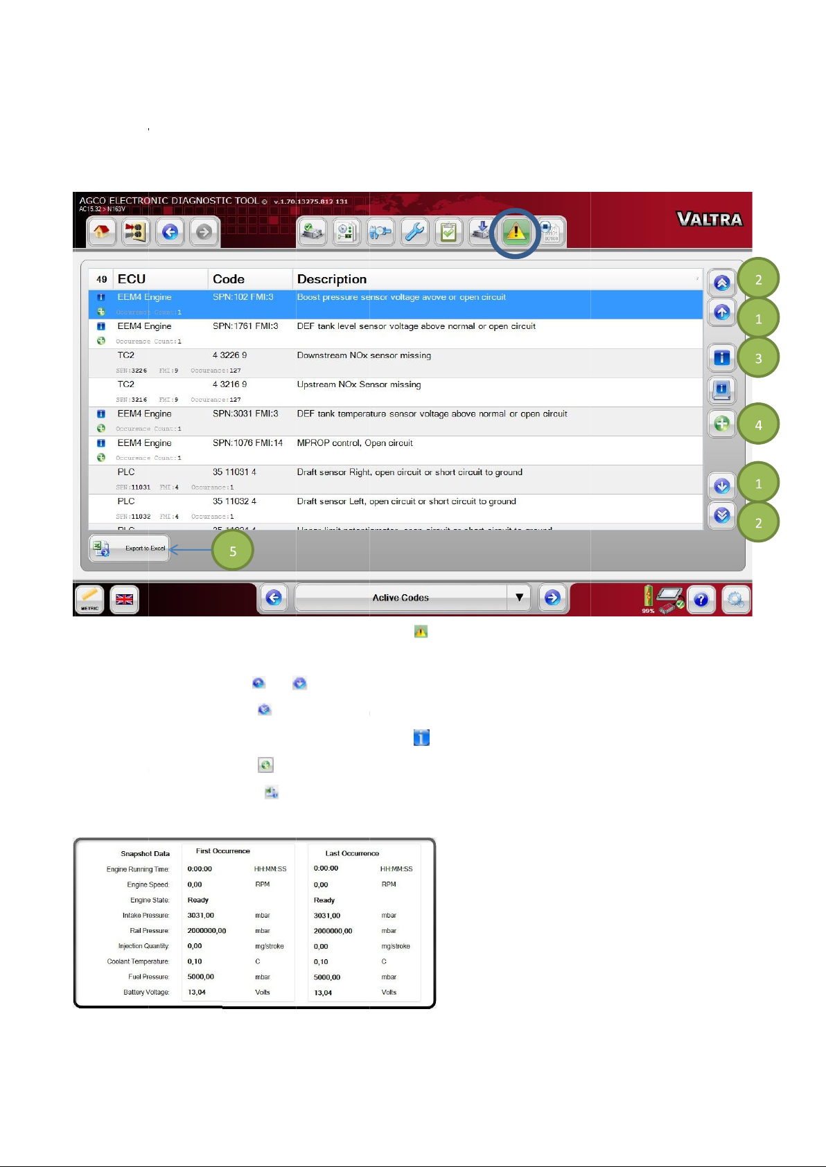
DIAGNOSTIC TROUBLE C
Active Codes
FIG.11
Any active fault code(s) resident with the controller on the vehicle ne
Select the
Select the
When the desired fault code is highlighted, select the
Select the
Select the
FIG.11
Select the
single arrow
double arrow
snapshot data
Export to Excel
Snapshot Data i
Diagnostic Trouble Codes (DTC)
icons
icons
s telling the information of first and last occurrence.
ODES
(2) to scroll through the pages.
(4) to retrieve the first and last occurrence information.
(5) to save the table based information to an Excel format.
(1) to scroll through the fault codes.
to run the DTC Script to read the trouble codes.
(3) to retrieve the diagnost
twork will be shown.
ic fault tree.
63
5
6
icon
or
i icon
icon
icon
Page 64
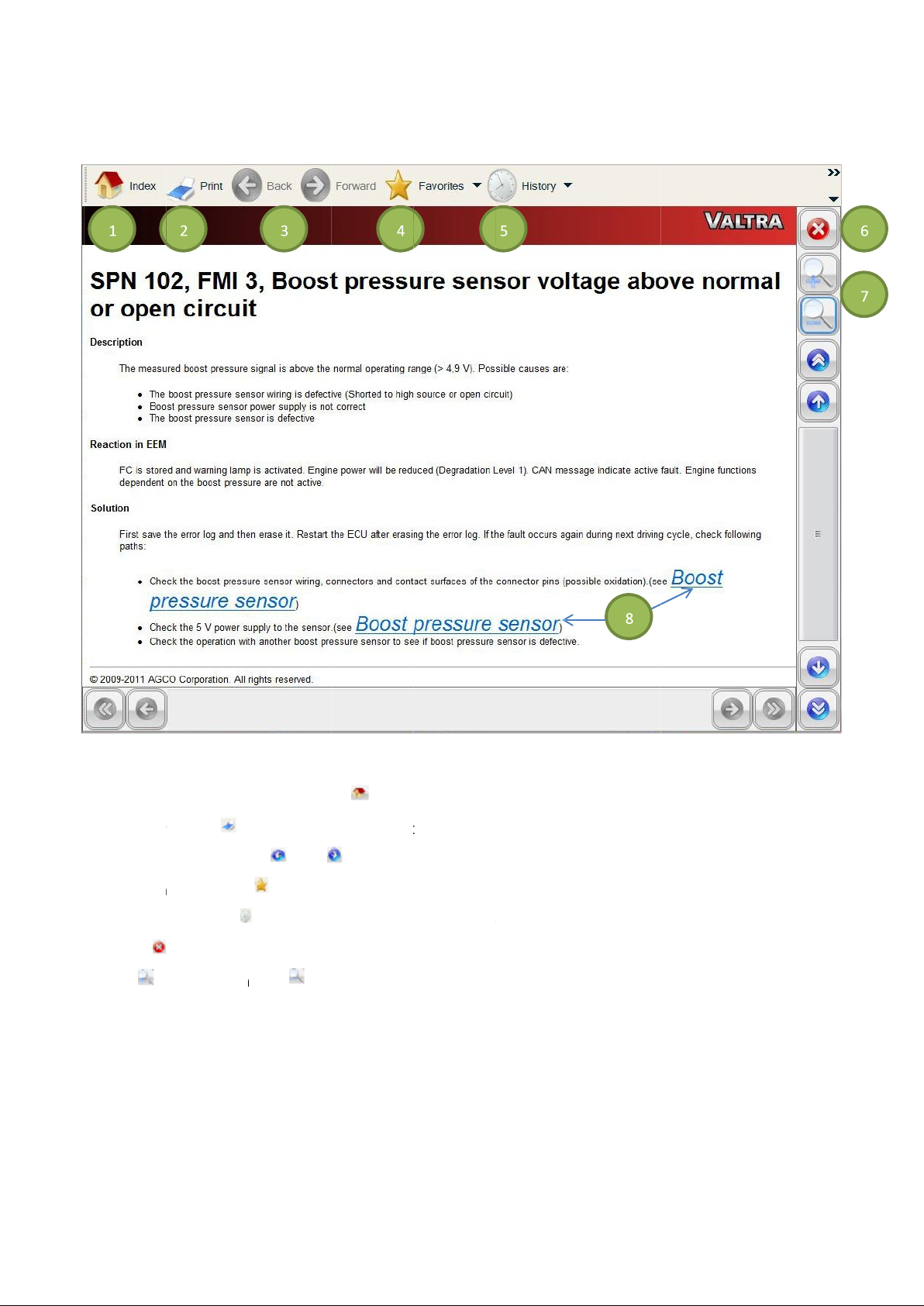
64
FIG.11
right.
At any time select the
Select the
Use the
Select the
Select the
Select the
Use the
Select a
Navigate under diagnostic fault tree by using the arrow icons or scroll
Print
navigation arrows
Favorites
History
icon to
(8) to display additional information (schematics, overview etc.).
Index
(2) to print the entire fault tree.
icon
Close
Zoom in
(8) to display additional information (schematics, overview etc.).
(Home) icon
(4) to view and to bookmark favorites.
(5) to show a list of files that have been viewed.
the fault tree.
icon to
(1) to show the fa
(3) at the top to go backward or forward.
Zoom out
ult tree index.
slider to move
up and down or left and
7
link
icon
icon
icon (6) to
or
and
(7).
Page 65
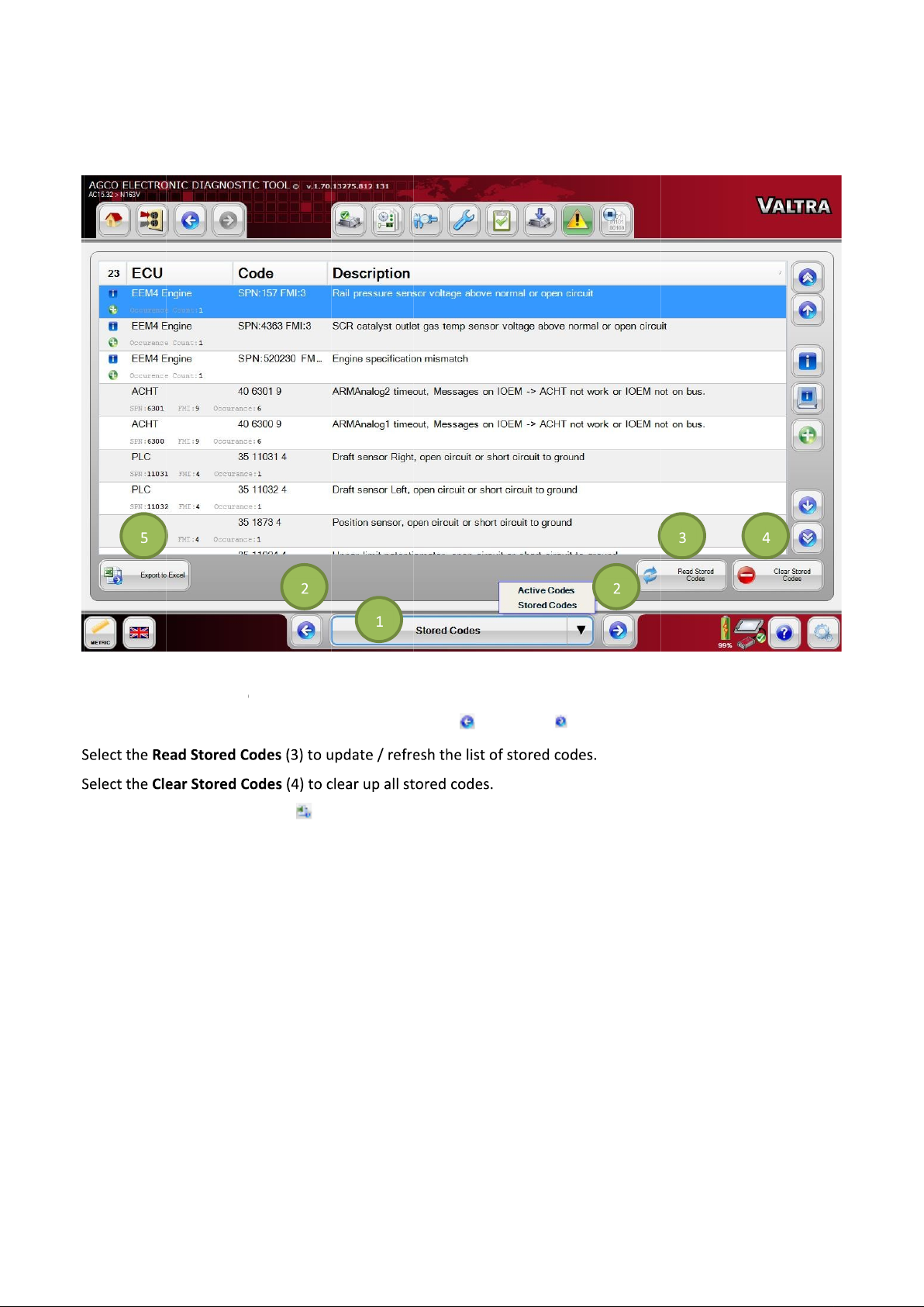
Stored Fault Codes
FIG.1
Select the icon (1) at the bottom center of the screen and select STORED CODES.
Navigate between the Active / Stored Codes using the
Select the
Select stored codes to view all stored fault codes for the controller on the vehicle network.
Export to Excel
(5) to save the table based information to an Excel
and
arrow icons (2).
format.
65
18
icon
left
right
Page 66
66
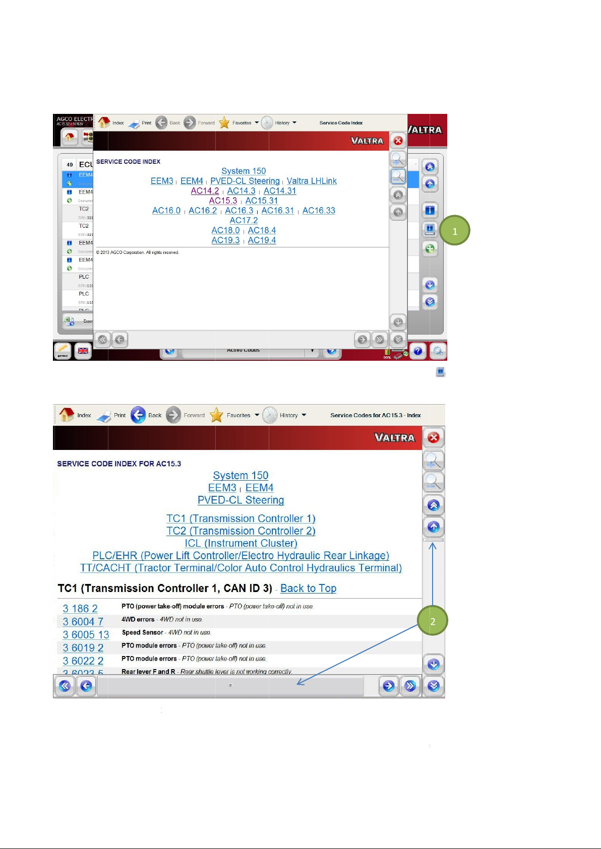
Fault Tree Index
FIG.1
FIG.1
Select a number to dis
Navigate through the fault codes using the scroll arrows or vertical and horizontal
From the fault code screen, view the Fault Tree Index by selecting the
All available fault codes for the vehicle selected will be shown listed in numerical order.
play the fault tree for that code or select an ECM at the top to display desired ECM fault codes.
icon
Scroll bars
19
i book
(1).
20
(2).
Page 67
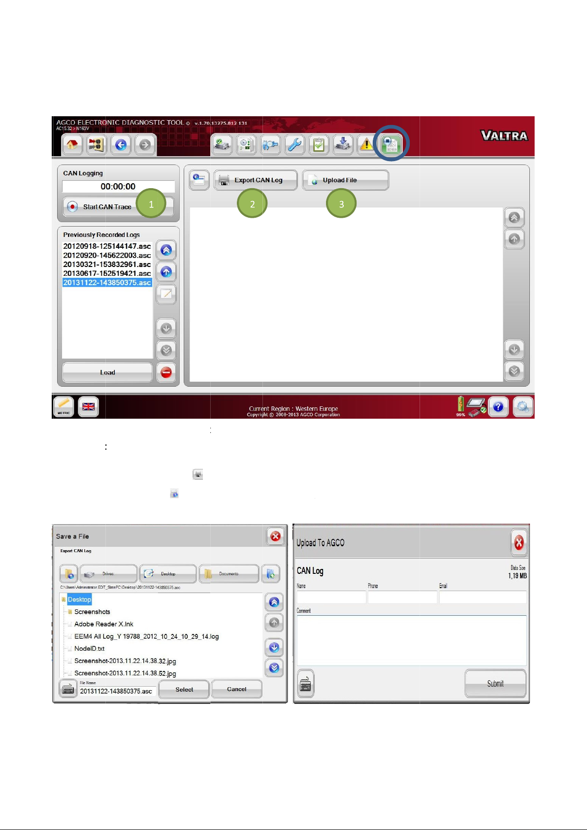
CAN TRACE
FIG.1
Select the
CAN Trace
Select the
Select the
FIG.12
Select the
Start CAN Trace
when selected.
Export CAN Log
Upload File
12 CAN Tr
icon 3 CAN logs can be sav
to run the Script to start recording of the CAN traffic.
icon (1) to record the CAN log. This icon toggles between
(2) to upload CAN logs (fo
) to upload individual CAN logs (for
ed to a fixed driv
r field use).
e, removable drive, CD rom, etc. or upload to AGCO server.
developer
Start CAN Trace
67
Stop
21
ace
icon
(3
and
use).
2 &
Page 68
68
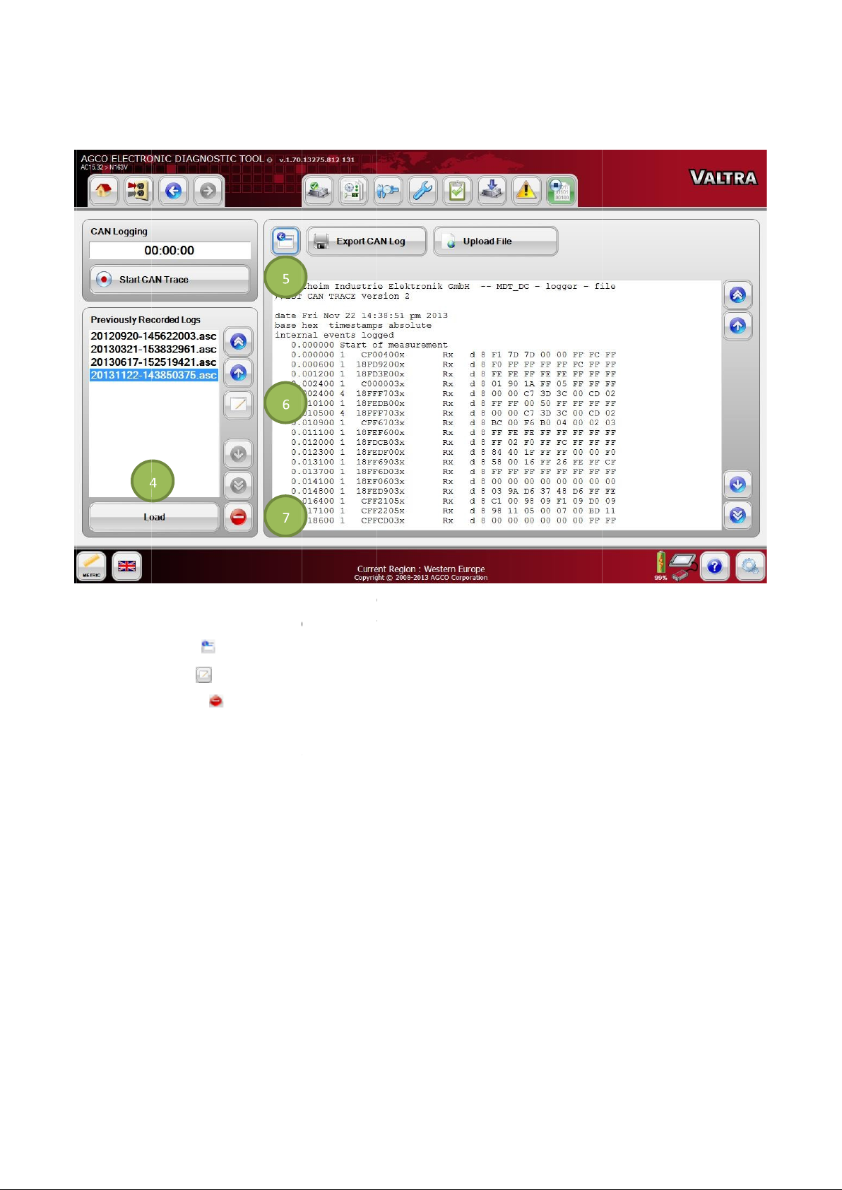
FIG.12
Select the
Select the
Select the
Selec
The CAN log files are in a standard .asc format that can be viewed in any plain text viewer, but is interpreted by AGCO
internal CAN engineering tools.
Select one of the recorded
Load
View
Edit
Delete
icon (4) to show the recorded CAN trace log.
(5) to toggle between full screen view and partial screen view.
(6) to change the name of the file.
file from the list on the left hand side.
(7) to delete a file.
4
t the
icon
icon
icon
Page 69
EDT LITE
The EDT Lite installation allows the following functions:
• Network Scan/Summary
• Interactive Graphical Diagnostics
• Calibrations
• Configurations
• Diagnostic Tests
• Retrieve Controller Error Codes
• Including Fault Tree Linkage
• Access to Fault Tree indexes
• CAN Tracing
EDT Lite will not be able to perform software flashing on the vehicle network controllers.
After installation on a computer EDT Lite will function for 180 days, after which the user will be notified to re-create the
application.
IMPORTANT: EDT Lite is not updated using the internet, but is a static application representing the full EDT application
it was created from.
EDT LITE INSTALLATION CREATOR
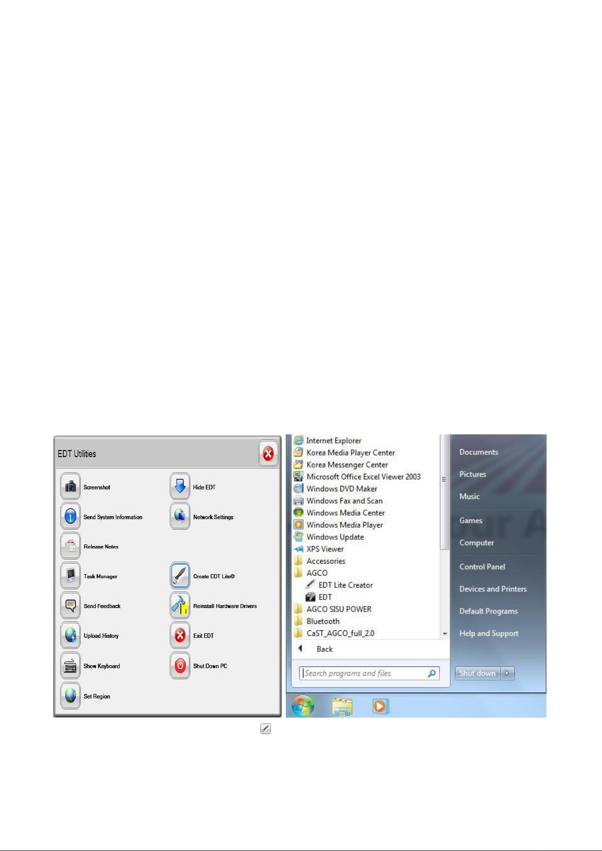
FIG.125 & 126 Select the Create EDT Lite icon under EDT Utilities to start the creator or from the desktop select
the Start icon, then All Programs > AGCO > EDT Lite Creator.
69
Page 70
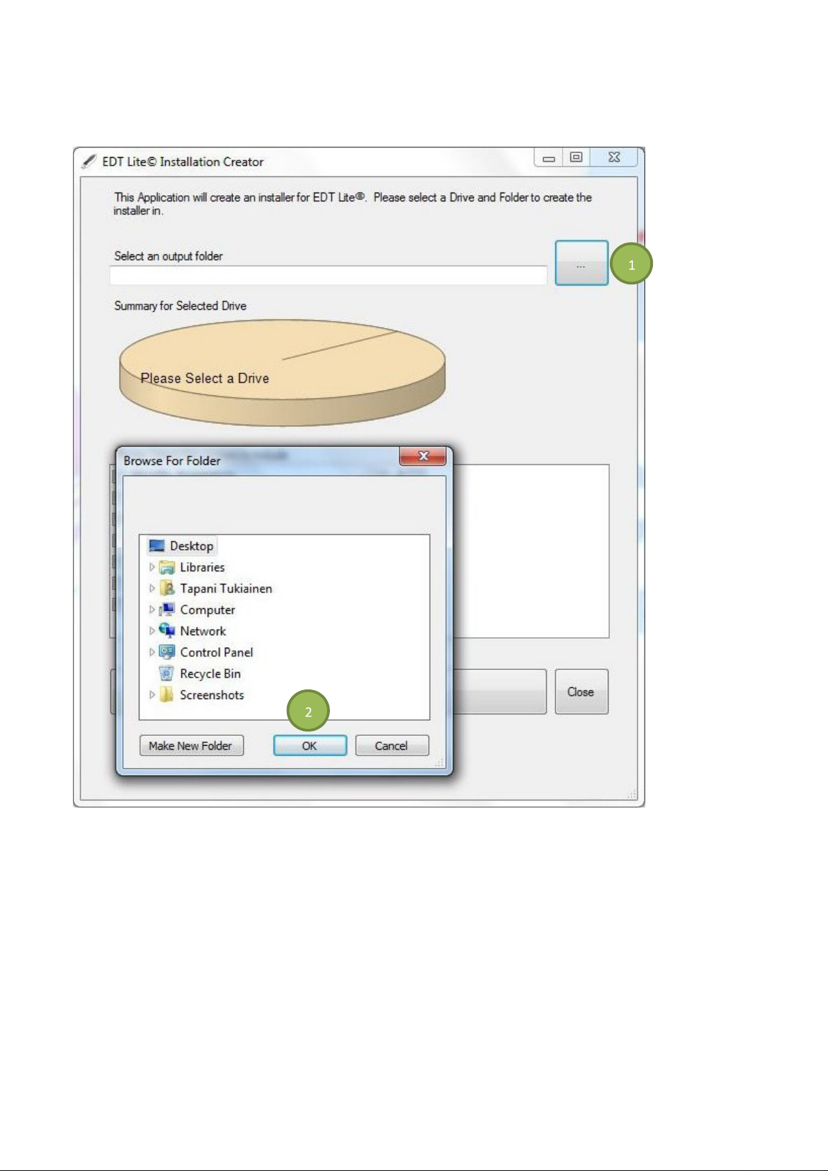
FIG.127 Select any drive (USB or physical) where the EDT Lite Creator is to be placed (target drive). If multiple
installations of EDT Lite are required, install the EDT Lite creator onto a USB memory device.
Select the icon (1) next to Select an output folder to load the folder browser
Select OK (2).
70
Page 71
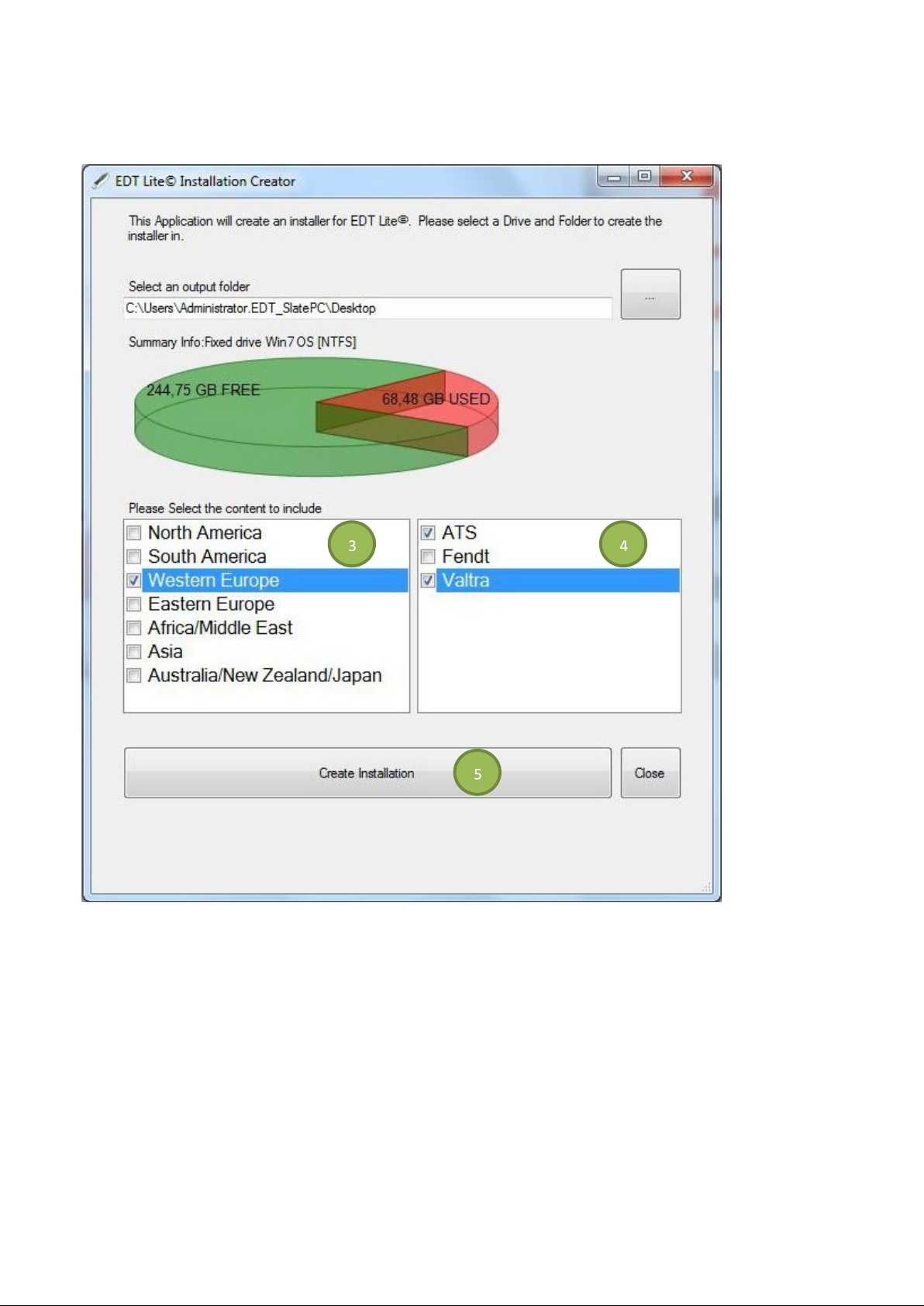
FIG.128 Select the content to be created for EDT Lite by selecting the box next to the required region (3).
Select brand (4) to be included for EDT Lite.
Select Create Installation (5) to start the process.
71
Page 72
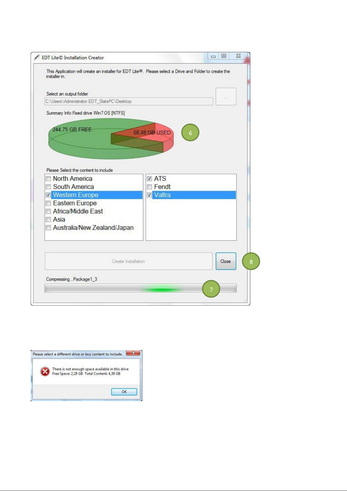
FIG.129 The target drive is monitored for available space during the process (6).
The progress bar shows the installation process (7).
Select the Close icon (8) when the process is complete.
FIG.130 If the target drive is not large enough, a dialog box will appear. To resolve do one of the following:
• Reduce the amount of content by deselecting brands and/or models.
• Increase the available size of the target drive.
72
Page 73
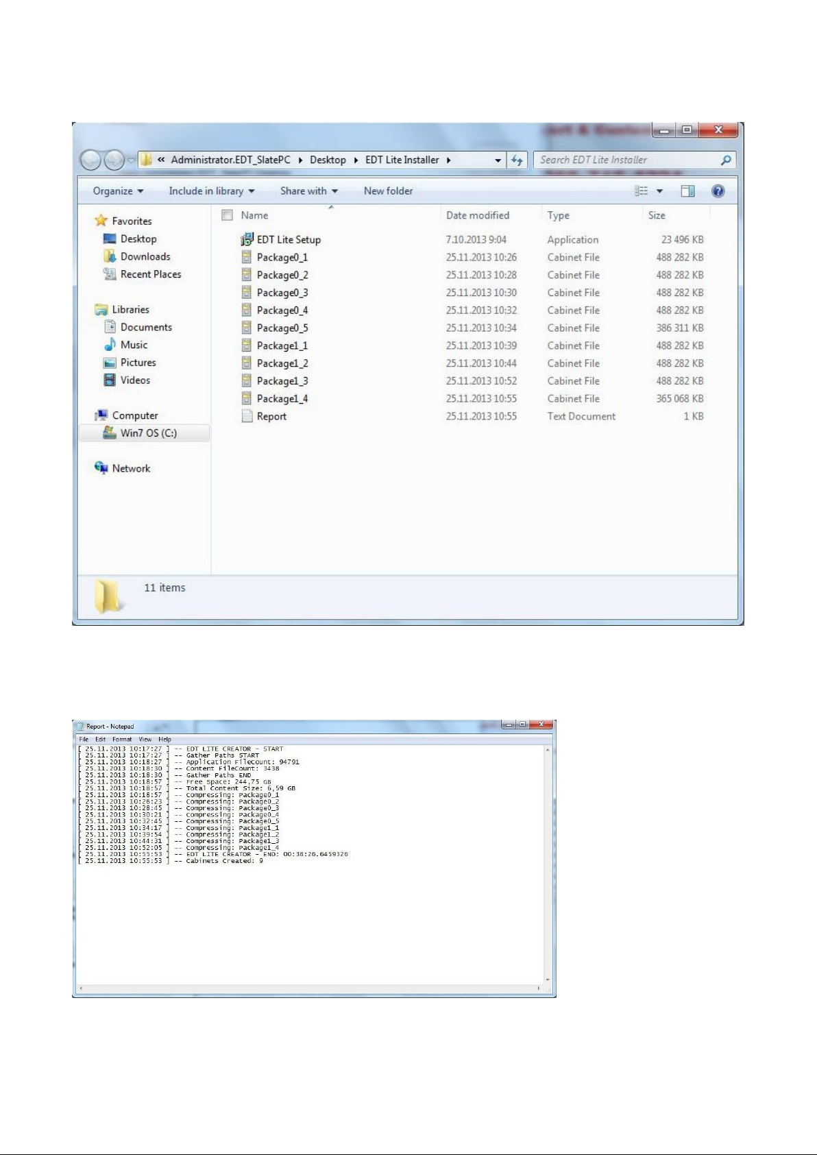
FIG.131 After the creation process is complete, the target drive folder is shown. Copy the new EDT Lite installation to
the network, burn to a CD, copy to a flash drive, or test by creating EDT Lite on the target drive.
NOTE! All of the files in this folder are required for the installation process.
FIG.132 Select and open the Report file to show the progress of EDT Lite creation.
73
Page 74
EDT LITE INSTALLER
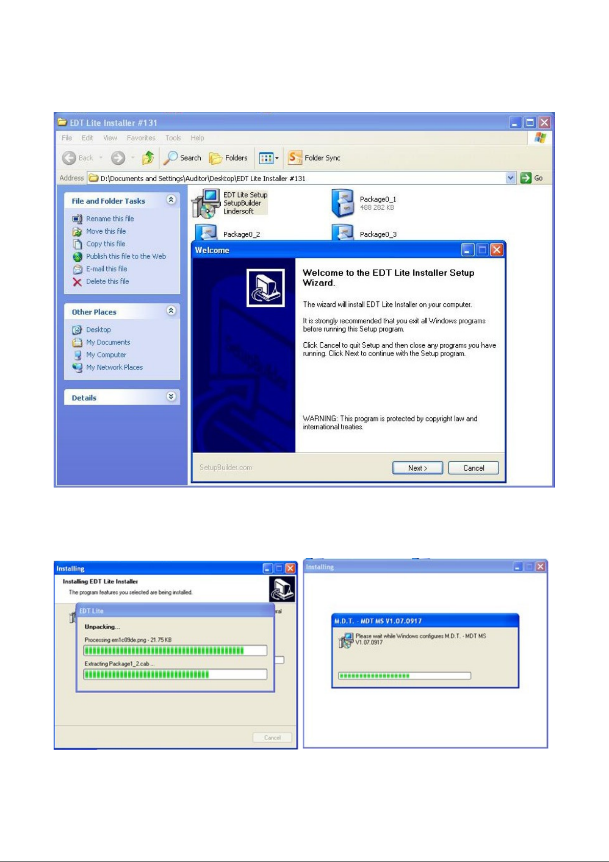
FIG.133 To install EDT Lite, attach the target drive to the computer where EDT Lite is to be installed. Navigate to the
target drive and locate EDT Lite Setup.exe. Double click on the file. Follow the instructions on the screen to install.
NOTE! It is recommended to copy the EDT Lite Installer folder from target drive to your PC due to faster installation.
FIG.134 & 135 Do not cancel the installation.
74
Page 75
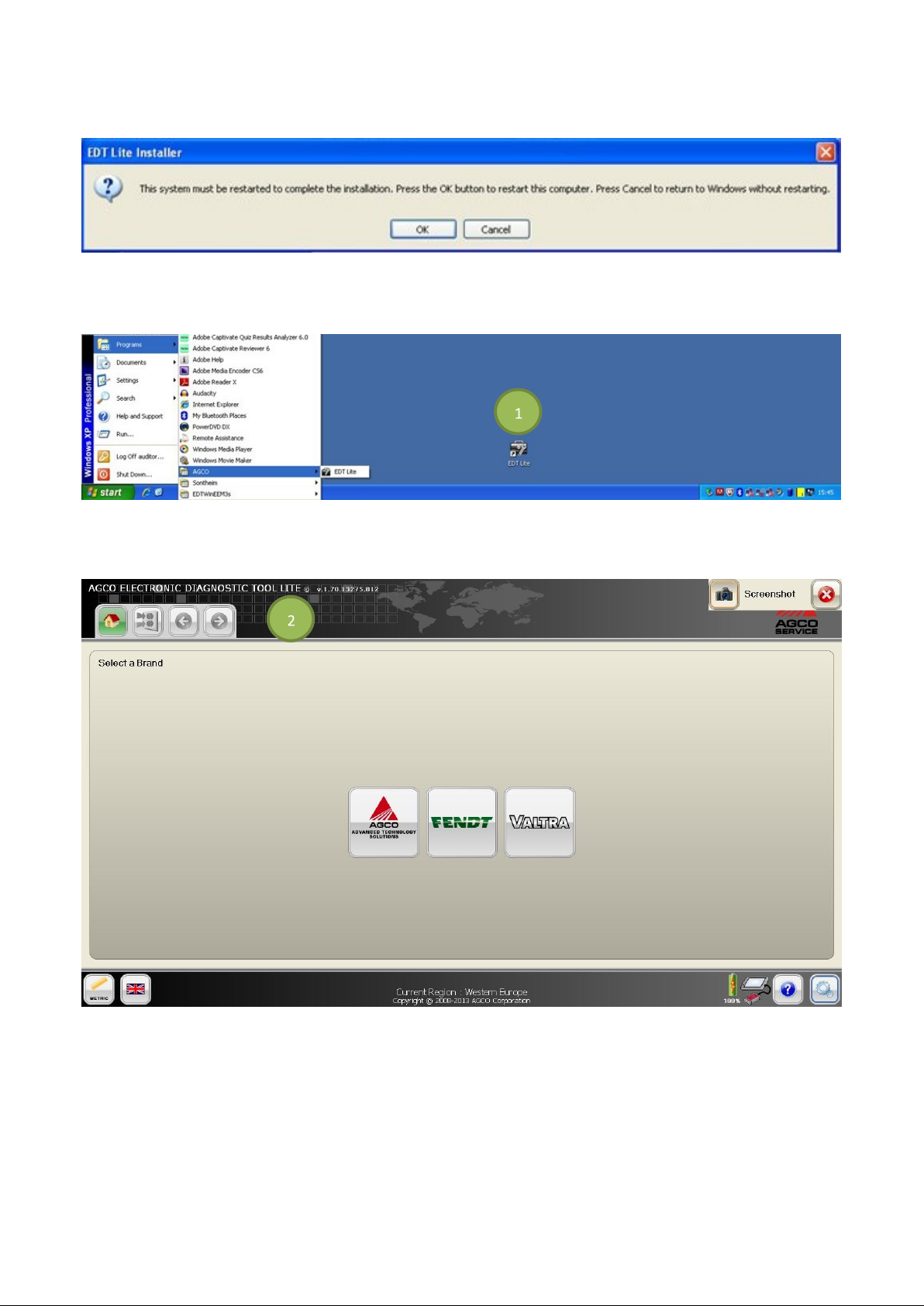
FIG.136 After the installation process is complete, restart the computer by selecting OK.
EDT LITE APPLICATION
FIG.137 After the installation process is complete, start EDT Lite from START > Programs > AGCO > EDT Lite (XP)
or START > Program Files > AGCO Corporation > EDT Lite (Win7), or select the shortcut (1) on the desktop.
FIG.138 The heading at the top of the screen identifies the Lite application (2).
Since EDT Lite is created from the full EDT application, there is no need to authorize the subscription license. All brands
the dealer can service are available from the brand selection screen.
NOTE: If the Select a Brand screen does not show any brand icons, EDT Lite was created from a non-registered
version of the full EDT application. EDT Lite must be created from a registered version of the full EDT
application.
75
Page 76
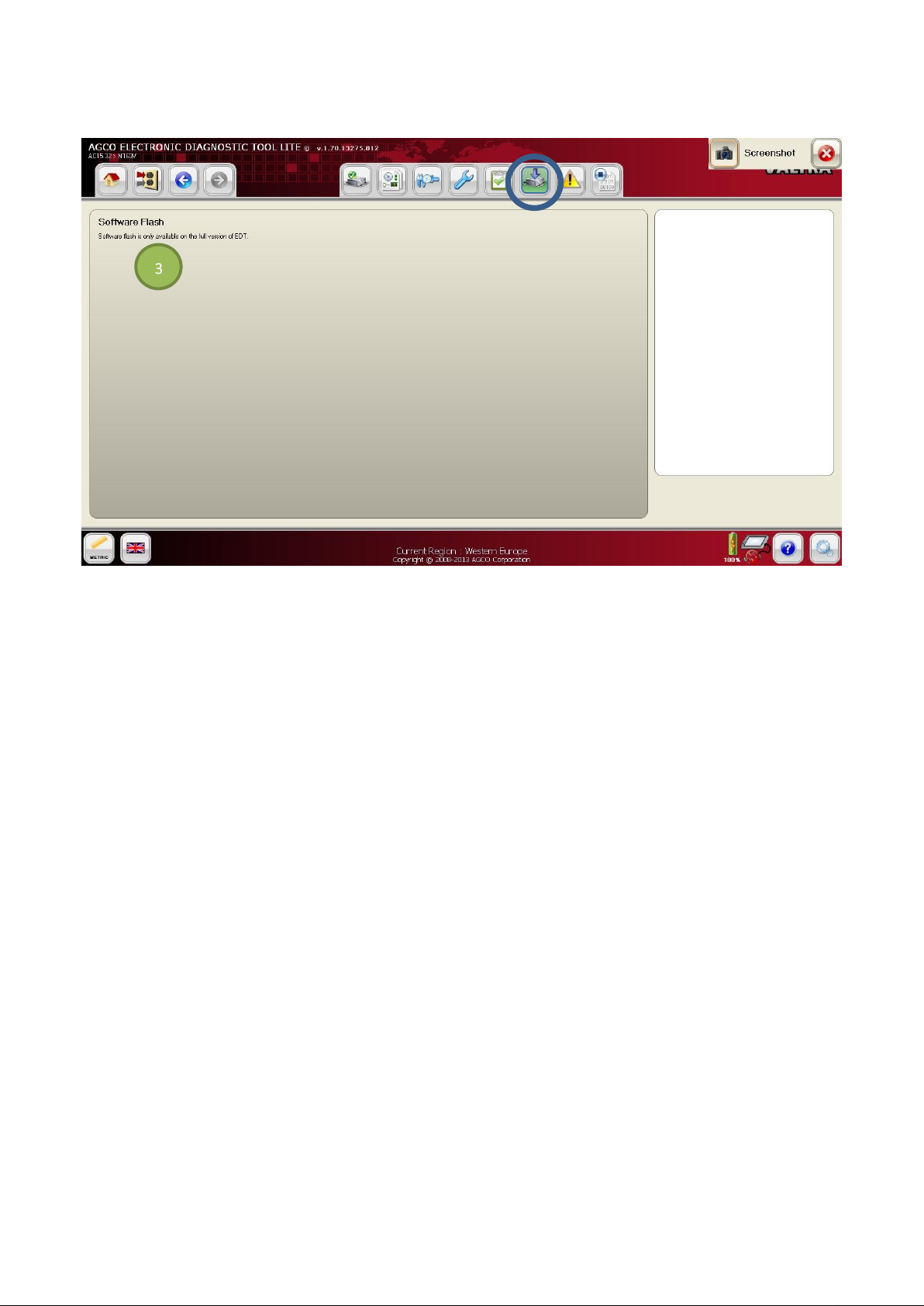
FIG.139 All seven function icons are shown, but according to a prompt (3) the software maintenance is not functional.
All other function icons work exactly like the full EDT application.
NOTE: For software maintenance on a vehicle, the full EDT application is required.
76
Page 77

INDEX
Numerics
2X4 CAN USB Vehicle Communication Interface .. 13
90 Degree USB Cable ........................................ 9, 13
A
Active Codes .......................................................... 63
Annual Subscription ................................................. 5
Audio In Jack ............................................................ 8
B
Battery LED .............................................................. 7
Battery Meter .......................................................... 35
Bluetooth Switch ................................................ 8, 15
Bump Case ............................................................... 9
C
Calibration ........................................................ 49, 59
CAN Network Status .............................................. 51
CAN Trace ........................................................ 49, 67
CAN USB Protocol Adapter ................................... 13
CAN-USB Presence ............................................... 38
CAN-USB Presence Icon ....................................... 35
Cigarette Lighter Adapter ....................................... 12
Cleaning the Screen ............................................... 17
Configuration .................................................... 49, 60
Connecting to a LAN Network ................................ 16
Connecting to a Wireless Network ......................... 15
Contents ................................................................... 3
Convenience Kit ..................................................... 11
D
DC In ................................................................... 8,14
Diagnostics by Function ................................... 49, 52
Diagnostic Connection Selection ........................... 49
Diagnostic Terminal ................................................. 6
Components .......................................................... 7
Durability ............................................................. 17
Set-Up ................................................................. 14
Touch Screen ........................................................ 9
Diagnostic Test ....................................................... 61
Diagnostic Trouble Codes ................................ 49, 63
Diagnostics Reporting ............................................ 55
Diagnostics Summary ............................................ 54
Digital Video Out ...................................................... 8
Docking Station ...................................................... 12
77
Page 78

E
EDT Lite Application ............................................... 75
EDT Lite Installation Creator .................................. 69
EDT Lite Installer .................................................... 74
EDT Software ......................................................... 18
eSATA ...................................................................... 8
Ethernet Port ............................................................ 8
Exit EDT ................................................................. 46
EyesBoard Application ........................................... 27
F
Fault Tree Index ....................................................... 66
Firewire 400 .............................................................. 8
G
Getting Started ....................................................... 35
Graphical Diagnostics ............................................ 53
Graphic Screen ...................................................... 53
H
Hard Drive LED ........................................................ 7
Headphone Jack ...................................................... 8
Help .................................................................. 35, 36
Hide EDT ................................................................ 45
Home Page ............................................................ 37
I
Index ....................................................................... 77
Individual File Flash ............................................... 62
Installation Procedure ............................................ 29
Internet Connection ................................................ 15
L
Laptop Requirements ............................................. 28
Language Selection ......................................... 35, 38
License Notification ................................................ 25
M
Machine Help Files ................................................. 48
Modular Expansion System ............................... 8, 14
N
Network Scan ................................................... 49, 50
Network Settings .................................................... 46
78
Page 79

Network Summary .................................................. 51
P
Power Switch ...................................................... 8, 14
Print ........................................................................ 64
Printer ..................................................................... 34
R
Region Set-Up .................................................. 21, 22
Registration ............................................................ 19
Reinstall Hardware Drivers .................................... 46
Release Notes .................................................. 25, 42
RJ45 Connector ....................................................... 8
S
Screen Cleaning Cloth ........................................... 11
Screen Protector .............................................. 11, 17
Screenshot ....................................................... 39, 40
Send Feedback ...................................................... 43
Send System Information ....................................... 41
Set Region .............................................................. 45
Shut Down PC ........................................................ 46
Signal Play Back .................................................... 56
Signal Trace ........................................................... 57
Snapshot Data ........................................................ 63
Software Flash ................................................. 49, 62
Software Package Flash ........................................ 62
Software Updating .................................................. 23
Speaker .................................................................... 7
Stored Fault Codes ................................................ 65
Stylus Pen .................................................................. 8
Subscription License .............................................. 20
Suction Cup Work Platform .................................... 10
System Check ........................................................ 41
T
Task Manager ........................................................ 43
Terminal Connections ............................................ 15
Touch Screen ........................................................... 9
U
Unit Selection ................................................... 35, 37
Update Process Notification Icon ........................... 23
Update Release Notes ........................................... 25
Update Service Message ....................................... 25
Updating ................................................................. 24
Uploads ............................................................ 23, 24
USB 2.0 .................................................................... 8
USB Port ................................................................ 16
79
Page 80

User Feedback ....................................................... 43
Utilities .............................................................. 35, 39
V
Vehicle Communication Interface .......................... 13
Vehicle Selection .................................................... 47
View Uploads ......................................................... 44
W
WiFi Switch ......................................................... 8, 15
Work Platform ......................................................... 10
80
 Loading...