

AGC Pro8-MD Maintenance Manual
AGC Model Pro8-MD
Operation and Maintenance Manual


Eastern Factory Central Western Factory
Table of Contents
Scope: ........................................................................................................................................ 1
Receiving and Inspection: .......................................................................................................... 1
Frame Placement: ...................................................................................................................... 2
Normal Operation: ...................................................................................................................... 3
Closing the Frame: ..................................................................................................................... 4
Opening the Frame: ................................................................................................................... 5
Operator Maintenance: ............................................................................................................... 6
Parts List: ................................................................................................................................... 8
Pro8 Plate and Port Gaskets ............................................................................................... 9
Pro8-MD Follower Spindle Components ........................................................................... 10
Pro8-MD End Support Spindle Components ..................................................................... 11
Pro8-MD Fixed End Spindle Components ......................................................................... 12
Pro8-MD Spindles and Rails ............................................................................................. 13
Pro8-MD Terminal and Port Bosses .................................................................................. 14
10129 Piper Lane 8400 Lakeview Parkway 3109 NE 230th Avenue
Bristow, Virginia 20136 Suite 700 Fairview, Oregon 97024
Phone 703-257-1660 Pleasant Prairie, WI 53158 Phone 503-774-7342
Fax 703-330-7940 847-301-6890 Fax 503-774-2550
800-825-8820 888-489-8820 800-715-8820
www.agcheattransfer.com
Released 7/16/2020

Scope:
This manual is intended to be a supplement to the AGC Heat Transfer Proflow Operation Manual.
The information provided here is for the normal operation and installation of the AGC Model Pro8-MD
Plate Heat Exchanger. Please read and follow all safety instructions contained in this manual. Failure to
follow all safety recommendations could result in serious injury to the operator or cause damage to the
press. If you need additional information or spare parts for this or any other equipment built by AGC
please contact your local AGC distributor.
Receiving and Inspecti on:
Each AGC frame is assembled and fully tested at the factory prior to shipping. After testing, the
unit is prepared for shipping. When the press leaves the factory it is in perfect condition. Upon arrival,
carefully inspect the frame for any damage that may have occurred during shipping. If you notice any
damage note it on the shipping paperwork and report it to AGC immediately. If possible, take photographs
of the damage.
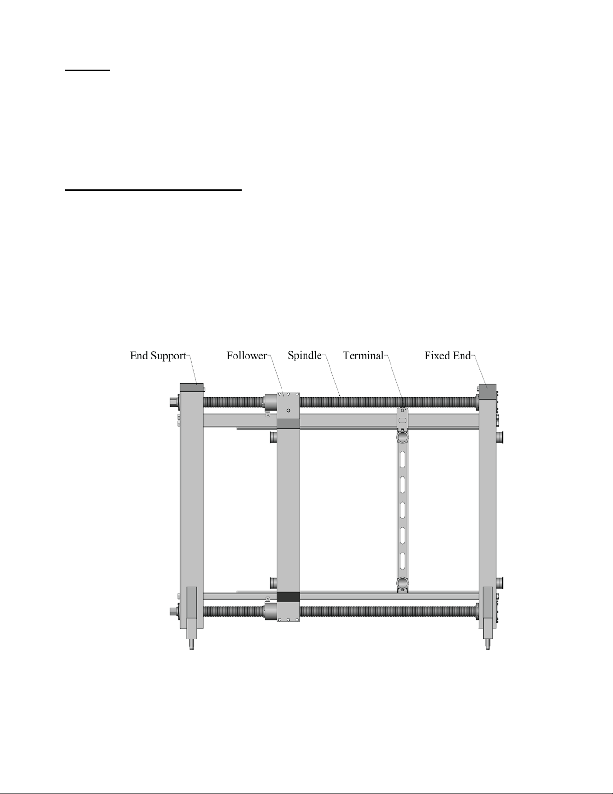
In most cases the heat exchanger is shipped assembled with the plates in a separate crate. Since
heat exchangers can be very large heavy machines, only qualified and licensed forklift truck drivers should
lift and position the frame. Figure 1 shows the major frame components. Depending on the application,
your frame may or may not be equipped with one or more terminals.
Figure 1
Major Frame Components
1
Each heat exchanger, also referred to as a frame, is shipped with a drawing package. This drawing
package contains important information specific to your heat exchanger. Locate the drawing package that
was shipped with your frame. If your frame was delivered without a drawing package, contact AGC or
your local AGC distributor for a replacement package prior to installing the frame.
Frame Placement:
When installing an AGC Pro8-MD heat exchanger it is important to select a n appropr iate location
for the unit. The frame should be located on a firm flat surfa ce capable of sup porting the press an d all of
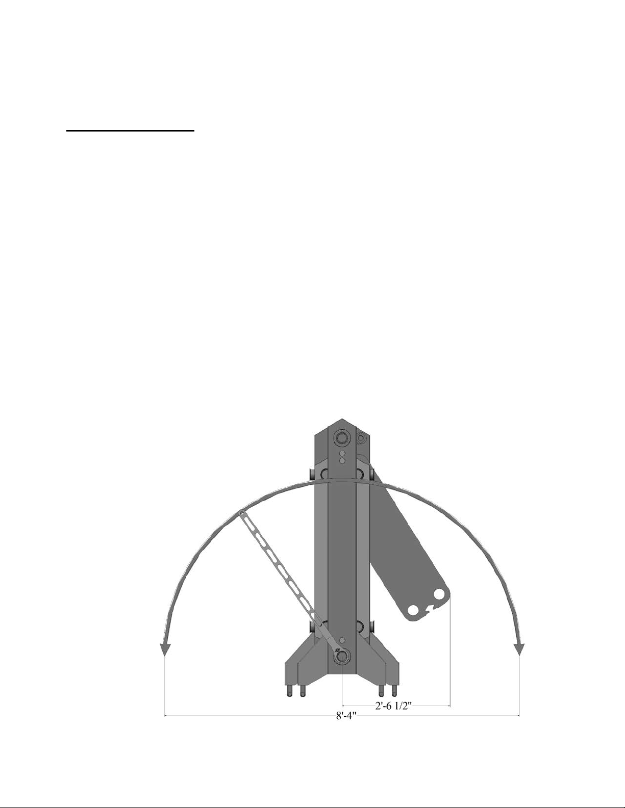
its contents when full. Ensure that adequate space is left around the frame for maintenance and plate
installation/removal. Installing or removing the plates is accomplished by tilting the plate over bottom
rail and around the top hanger. Plate installation requir es abou t 2 ½ feet, as measured from the center line
of the machine, to allow the plate to swing unobstructed. See Figure 2a. This space is required on at least
one side or preferably both sides of the heat excha nger. Additionally, space should be left adjacent to the
end support for rotating the AGC FatBoyTM wrench to open or close the press. This is about 4 feet on
each side of the end support.
The heat exchanger is designed with lifting points on the fixed end and the end support. See figure
2b. These lifting points are designed to receive a standard ¾-10 threaded fastener. To access the lifting
points, remove and retain the stainless-steel hex bolts and sealing washers located above the top spindle.
Install lifting rings rated for at least 3000 pounds on the fixed end and end support. Once the heat
exchanger is in place it must be leveled. Each frame is equipped with adjustable ball feet to compensate
for minor floor variations. To adjust the ball foot height, turn the base of the foot clockwise to raise and
counter clockwise to lower. CAUTION: Never exceed the maximum port height dimension shown on
the streaming diagram. If this dimension is exceeded, the leg could disengage from the socket and the
frame could tip. Once the heat exchanger is in place and leveled, remove the lifting rings and re-install
the stainless-steel hex bolts and sealing washers.
2
 Loading...