

“Building the Best,
Servicing the Rest”
™
AGC Model pro3
Plate Heat excHanger OPeratiOn
and installatiOn Manual

Table of Contents
Scope: . . . . . . . . . . . . . . . . . . . . . . . . . . . 1
Receiving and Inspection: . . . . . . . . . . . . . . . 1
Drawing Package: . . . . . . . . . . . . . . . . . . . 2
Frame Placement: . . . . . . . . . . . . . . . . . . . . 3
Frame Connections: . . . . . . . . . . . . . . . . . . 5
Normal Operation: . . . . . . . . . . . . . . . . . . .6
Opening the Heat Exchanger: . . . . . . . . . . . .7
Operator Maintenance: . . . . . . . . . . . . . . . . 8
Model Features: . . . . . . . . . . . . . . . . . . . . .8
Parts List: . . . . . . . . . . . . . . . . . . . . . . . . .10
Pro3-SH Frame Components . . . . . . . . . 11
Pro3-S Frame Components . . . . . . . . . . 12
Pro3-F/I Frame Components . . . . . . . . .13
Pro3-DFH Frame Components . . . . . . . . 14
Pro3-DF Frame Components . . . . . . . . . 15
Pro3-I Tiebolt Assembly . . . . . . . . . . . . 16
Pro3-S/SH Tiebolt Assembly . . . . . . . . .17
Pro3-F/DF/DFH Tiebolt Assembly . . . . . .18
Pro3 Terminal Assembly . . . . . . . . . . . .19
Pro3 Plate and Frame Gaskets . . . . . . . .20
Eastern Factory
10129 Piper Lane
Bristow, VA 20136
Phone 703-257-1660
Fax 703-330-7940
800-825-8820
Central Office
8400 Lakeview Parkway
Suite 700
Pleasant Prairie, WI 53158
Phone 847-301-6890
888-489-8820
www.agcheattransfer.com
Western Factory
9109 SE 64th Avenue
Portland, OR 97206
Phone 503-774-7342
Fax 503-774-2550
800-715-8820

Scope:
This manual is a supplement to the AGC Heat Transfer ProFlow plate heat exchanger manual.
We recommend you read the ProFlow manual first because it will provide you with a basic
understanding of plate heat exchangers and define the technical terms used in this
document. The information provided within this manual describes the installation, operation, and
maintenance of the AGC Heat Transfer Pro3 tiebolt style heat exchangers. Currently 6 (six)
different models of the Pro3 tiebolt style heat exchangers are available and this manual covers all 6.
Please read this manual carefully before installing your heat exchanger. Pay particular
attention to the safety instructions and the initial startup procedures. Failure to follow all safety
recommendations could result in injury to the operator or cause damage to the heat exchanger.
Receiving and Inspection:
Each AGC heat exchanger is assembled and fully tested at the factory prior to shipping. Once
the unit has successfully passed all tests it is prepared for shipping. Every AGC heat exchanger
is thoroughly inspected to ensure it is in perfect condition before leaving the factory. Upon
arrival, carefully inspect your new heat exchanger for any damage that may have occurred
during shipping. If the press was damaged during shipping make sure it is annotated on the
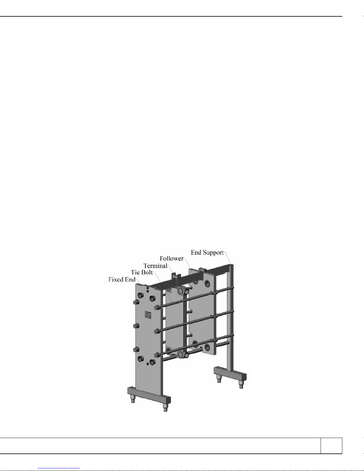
shipping documents. Also, report any damage to AGC immediately. To aid you in describing
where any damage may have occurred, figure one shows the major components of a typical
Pro3 frame with one terminal.
800.825.8820 eastern I 888.489.8820 central I 800.715.8820 western I www.agcheattransfer.com 1
Figure 1
Major Frame Components
Normally, tiebolt style frames are shipped with the plates installed. As a result the press and
plates can weigh several thousand pounds. We recommend only qualified forklift drivers should
lift and position the unit. It should be noted that high leg frames such as the Pro3-SH and
Pro3-DFH can be top heavy and could tip if they are not moved properly.
Drawing Package:
Every frame is shipped with a drawing package. This drawing package contains important information
that is specific to your heat exchanger. If you cannot find the drawing package, contact AGC Heat Transfer
or your local AGC distributor to obtain a replacement prior to installing the heat exchanger.
The drawing package is a collection of several important documents related explicitly to your
heat exchanger. The first of these is the streaming diagram. Two copies of the streaming
diagram are included. One copy has been laminated to protect it. This copy is intended to be used
by production and maintenance personnel when installing and/or servicing the heat exchanger.
The remaining copy should be kept on file in a safe place in the event the production copy is
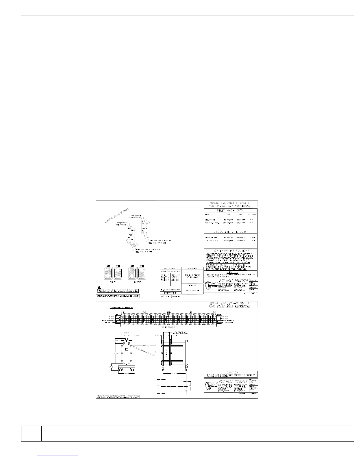
lost or damaged. The streaming diagram (also referred to as the drawing) describes all the
characteristics of the heat exchanger. Figure 2 shows a typical two page streaming diagram.
2 AGC Heat Transfer I Pro3 SerieS
Figure 2
Typical Streaming Diagram
Page one shows the unit serial number, the duty, plate type, plate count, gasket type,
connection type, connection size, and the tightening dimension. Revisions are also listed
on page one. Page two of the drawing shows how the fluids pass through the heat
exchanger. (The ProFlow manual describes how to read this flow diagram). If the unit is
small, such as the unit in figure two, a front and side view of the heat exchanger will be shown
as well. For larger units the front and side views are shown on page three or page four
.
The second document in the drawing package is a plate punching diagram. This
diagram will show you how to identify each Pro3 plate either by its configuration number
(stamped at the top of each plate) or by looking at the plate noting which ports have been
opened. Since the Pro3 plate is a vertical flow plate, each plate can be used for either a right
or left hand plate. The ProFlow manual explains how these plates are used in greater detail.
The final document in the drawing package is the ProFlow manual. The ProFlow
manual has information about the AGC Heat Transfer product line and a more in-depth
discussion about plate heat exchangers in general
.
Frame Placement:
Locate the Pro3 frame on a firm flat surface capable of supporting the press and all of
its contents when full. If possible, the frame should remain strapped to the shipping skid
until it is near its final location. Once the press is positioned cut the metal bands holding it
to the shipping skid and, using an appropriately sized lifting strap, carefully lift the press off
the skid. The top rail can be used as a lifting point. Never lift the press by the tiebolts or
port nozzles. These bolts are in slots and are not designed to support the weight of the
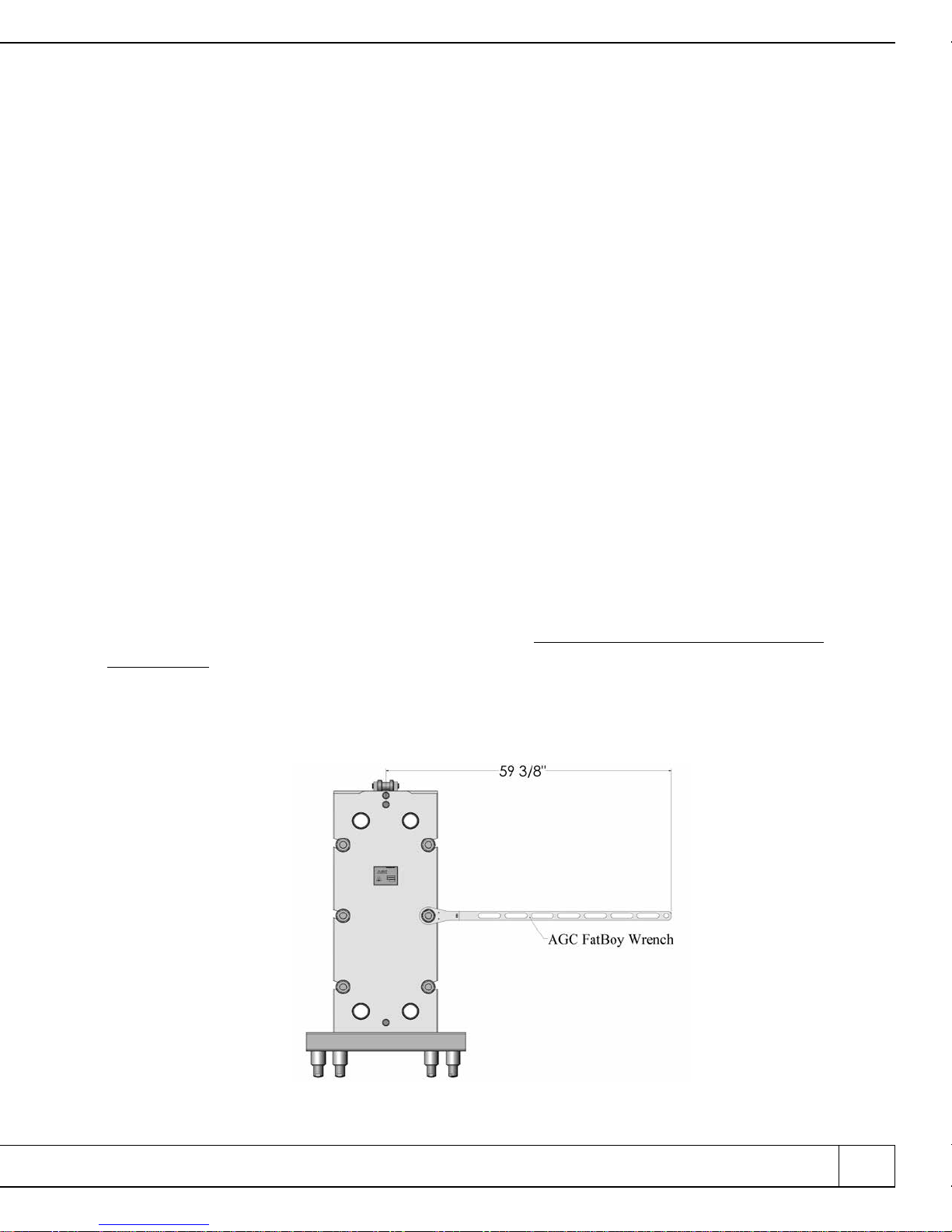
frame for lifting. When locating the heat exchanger, ensure that adequate space is left
around the frame for maintenance and for plate installation/removal. Also include enough
space to allow the AGC Fat Boy
™
wrench to fully swing. See figure 3.
800.825.8820 eastern I 888.489.8820 central I 800.715.8820 western I www.agcheattransfer.com 3
Figure 3
Wrench Space Requirement
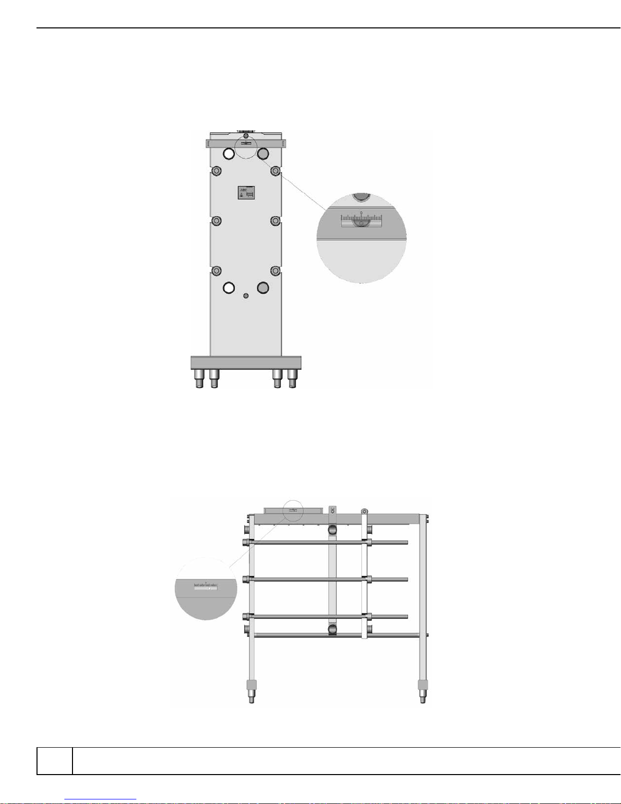
The Pro3-SH, Pro3-S, Pro3-DFH and Pro3-DF frames are equipped with adjustable ball
feet. These feet are adjusted by turning the base clockwise to lower and counterclockwise to
raise the press. The ball feet should be adjusted so the ports are level from side to side.
Figure 4 shows a spirit level placed across the ports to establish level.
Figure 4
Port Leveling
Once the ports are level the heat exchanger should be adjusted so it will drain
properly. This is done by adjusting the ball feet to establish a slope from end to end.
Figure 5 shows a press adjusted to drain forward to the fixed end.
4 AGC Heat Transfer I Pro3 SerieS
Figure 5
Frame Adjusted to Drain to Fixed End
Consult your onsite Plant Engineer or Project Manager to determine how much slope
and which direction (toward the fixed end or follower) is appropriate for your installation.
The Pro3-I and Pro3-F frames are built with flat foot pads that are designed to be bolted to the
floor. Therefore, no provisions for leveling are designed into the frame. However, these frames
can be leveled by adding an appropriate amount of filler material under each foot pad as required.
Frame Connections:
Careful planning during the installation of your new heat exchanger will help ensure years
of trouble free operation. All piping connections should be well supported and carefully
aligned with the ports on the heat exchanger. Misaligned pipes or pipes that are not properly
supported can lead to connection failures or cracks in the welded joints. When laying out a
new installation, include enough breaks in the piping so service and maintenance can be
completed easily. The piping connected to the follower should be configured with joints that
are easy to remove so the follower can be fully retracted. This will provide enough space for
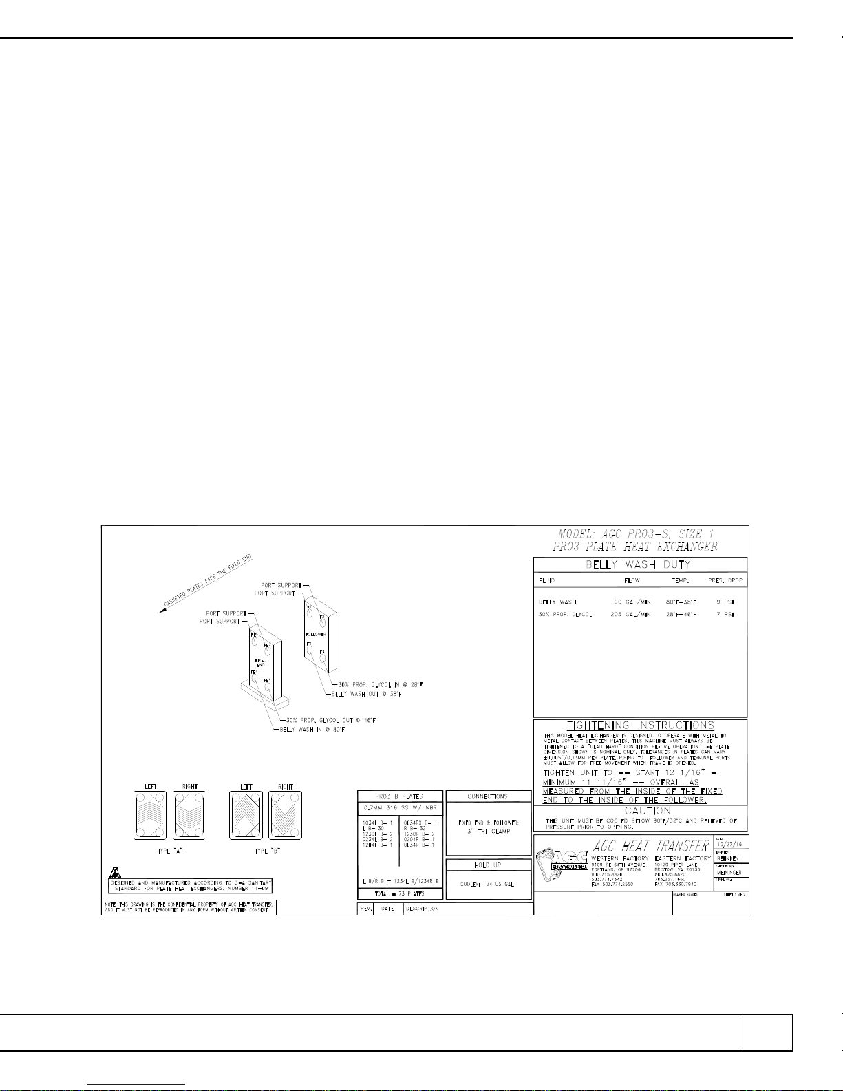
clear inspection of the heat exchanger plates. The streaming diagram will show where all
external connections should be made. Figure 6 shows page one of a typical streaming
diagram for a single section design heat exchanger.
Notice that all ports have labels that clearly state what is to be connected to each one.
800.825.8820 eastern I 888.489.8820 central I 800.715.8820 western I www.agcheattransfer.com 5
Figure 6
Typical Streaming Diagram

Normal Operation:
The Pro3 series heat exchangers are tiebolt style frames. This means the press is closed
by using 6 tiebolts to compress the plates. For this type of frame it is important for each
tiebolt to take an equal share of the load. After your heat exchanger is in place you should
check the compressed dimension if the plates were shipped installed. The dimension for your
heat exchanger is listed on the first page of your streaming diagram. Figure 7 shows where
the tightening dimension is located on the drawing. If the plates were shipped in a separate
crate refer to the ProFlow manual for instructions on installing them.
Figure 7
Tightening Instructions
Most new plate packs will seal at the start dimension. As the plates and gaskets wear it
may be necessary to compress or close the press further. You should never exceed the
minimum dimension shown on the streaming diagram. If your press is closed to the minimum
dimension and leaks are noticed contact AGC Heat Transfer for technical assistance. Closing
the press beyond the minimum dimension could cause permanent damage to the plates,
frame, or both. When measuring the compressed dimension it is a good practice to take the
measurement in several locations on the inside of the fixed end and follower as shown in figure 8.
6 AGC Heat Transfer I Pro3 SerieS

Figure 8
Tightening Location and Sequence
Measure top and bottom as well as front and back. The heat exchanger is designed operate
at its top efficiency when it is closed to a metal to metal condition. This means the rubber plate
gaskets are fully compressed and the plates contact points are fully engaged with each adjacent
plate. In this condition, the plate gap is uniform and the plate is fully supported. To maintain
this condition all tiebolts should be tightened equally and in sequence. Following the sequence
shown in figure 8, tighten each tiebolt in small increments so the follower remains parallel to
the fixed end. As the press approaches the start dimension smaller increments at each bolt will
make for easier closing.
After the press is closed and all connections are made to the heat exchanger the unit is ready
to be pressure checked. Consult the onsite plant engineer or project manager for the correct
procedure on pressure testing the press.
Opening the Heat Exchanger:
Before opening this or any other heat exchanger you must verify the temperature in the unit
is below 90° F and that the unit has been relieved of all internal pressure. Failure to follow this
safety warning could result in serious injury to the operator or damage to the plates and gaskets.
All pipes/connections should be disconnected from the heat exchanger before the tiebolts are
loosened.
Prior to opening the press, inspect the tiebolts to ensure they are free from dirt or excessive
dust and that lubrication is present on each. Opening or closing the tiebolts without lubrication
may cause permanent damage to the tiebolt. Small increments on each bolt will make the process
easier and prevent damage to the press or any of its parts. The tiebolts should be loosened using
the same sequence as for tightening. See figure 8 for the bolt sequence. As with tightening, the
closer the unit is to the minimum dimension the more torque will be required on the Fat Boy
wrench. Once the plates are completely uncompressed, the tiebolts can be lifted from their slot.
Handle the tiebolts with care so the
800.825.8820 eastern I 888.489.8820 central I 800.715.8820 western I www.agcheattransfer.com 7
™

threads are not damaged. The follower can now be moved back toward the end support and the
plates can be inspected or removed.
Operator Maintenance:
All AGC Heat Transfer heat exchangers are designed to require minimal operator maintenance.
As long as the unit is operated within the pressure and temperature limits the only maintenance
required is routine cleaning, lubrication and inspection. We recommend the unit be leak checked
annually using the PlateCheck™ field service provided by AGC Heat Transfer. This service is
performed onsite by factory trained service engineers. The PlateCheck™ service provides a thorough
inspection of all parts of the heat exchanger. After the service is complete, a detailed written report
is provided on the condition of the heat exchanger. This preventative maintenance service greatly
reduces unscheduled down time by keeping the heat exchanger in peak operating condition.
Model Features:
The Pro3 tiebolt frame is offered in 6 different models (see figure 9). Regardless of the model
chosen, each Pro3 frame will accept the AGC Pro3 heat exchanger plates and one or more AGC
terminal(s). Additionally, all AGC heat exchangers can be fitted with special removable port nozzles.
This feature is particularly useful in applications where the product erodes the stainless steel nozzles.
The Pro3-S and Pro3-SH are stainless steel clad frames. Both models conform to the current
3A sanitary standards. The factory installs ports at all eight locations (4 on the fixed end and 4 on
the follower) on both models of these frames. The un-used ports are capped using sanitary caps
and clamps. This makes it very easy to expand the heat exchanger in the field to increase capacity
or to add other processes to the frame. The major difference between the –S and –SH frames is the
height of the port centers. The –SH frame is the high leg version. Both frames are equipped with
adjustable ball feet.
The Pro3-F and Pro3-I are powder coated mild steel frames. These frames are designed to be
bolted to the factory floor or other support structure. They utilize the Pro3 heat exchanger plate and
can be configured to have any of the eight available ports used. Typically these models are shipped
from the factory with ports installed at the active ports only. The un-used ports are blanked using a
stainless steel blanking disk. The major difference between the –F and –I models is the tiebolt mate
rial. The –F frame has stainless steel tiebolts with a silicon-bronze nut. The –I frame has galvanized
tiebolts with a stainless steel nut. Additional connecting ports can be ordered from the AGC factory if
the frame needs to be expanded or restreamed. New port nozzles may require some welding onsite
depending on the connections.
The Pro3-DF and Pro3-DFH are a lower cost alternative to the –S and –SH frames. These
frames have adjustable ball feet and a stainless steel leg base, but the main body of the frame is
powder coated mild steel. The tiebolts are stainless steel with silicon-bronze nuts. If these frames
are ordered with sanitary connections they will comply with the current 3A guidelines for sanitary
dairy equipment.
8 AGC Heat Transfer I Pro3 SerieS
-

Pro3-S Pro3-SH
Pro3-F Pro3-DF
Pro3-I Pro3-DFH
800.825.8820 eastern I 888.489.8820 central I 800.715.8820 western I www.agcheattransfer.com 9
Figure 11
Pro3 Tiebolt Frame Assemblies

Parts List:
Replacement parts for any AGC Pro3 frame can be ordered from AGC Heat Transfer or
from your local AGC Distributor. Most parts are in stock and can be shipped within 24 hours
from the time we receive your order. Some parts have been revised so it is important to have
your unit model and serial number available when placing an order for spare or replacement
parts. All models of the Pro3 heat exchangers have some parts that are common as well as
model specific parts. The following parts diagrams are separated by model when appropriate.
Most of the field replaceable parts are listed in this manual. If the part you need is not listed
on the following pages contact your local AGC distributor or the AGC Heat Transfer Factory.
Contact information is provided below or visit our website for more information:
Eastern Factory
10129 Piper Lane
Bristow, VA 20136
Phone 703-257-1660
Fax 703-330-7940
800-825-8820
Central Office
8400 Lakeview Parkway
Suite 700
Pleasant Prairie, WI 53158
Phone 847-301-6890
888-789-8820
www.agcheattransfer.com
Western Factory
9109 SE 64th Avenue
Portland, OR 97206
Phone 503-774-7342
Fax 503-774-2550
800-715-8820
10 AGC Heat Transfer I Pro3 SerieS

Pro3-SH Frame Components
Item No.
Pro3-SH Qty.
20
33
34
35
38
50
800.825.8820 eastern I 888.489.8820 central I 800.715.8820 western I www.agcheattransfer.com 11
Part Number
1
1
6
1
1
1
See Table on page 17
11018300
See Table on page 19
11018400
11018200
See Table on page 17
Description
Pro3 Bottom Rail
Pro3-S/SH Follower
Pro3-S/SH Tiebolt
Pro3-S/SH End Support
Pro3-S/SH Fixed End
Pro3 Upper Rail

Pro3-S Frame Components
Item No.
18
19
20
30
33
50
12 AGC Heat Transfer I Pro3 SerieS
Pro3-S Qty.
1
6
1
1
1
1
Part Number
11011610
See Table on page 19
See Table on page 17
11011611
11018300
See Table on page 17
Description
Pro3-S Fixed End Assembly
Pro3-S/SH Tiebolt Assembly
Pro3 Bottom Rail Assembly
Pro3-S End Support Assembly
Pro3-S/SH Follower Assembly
Pro3 Upper Rail Assembly

Pro3-F/I Frame Components
Item No.
2
21
22
23
32
33
800.825.8820 eastern I 888.489.8820 central I 800.715.8820 western I www.agcheattransfer.com 13
Pro3-F/I Qty.
1
1
1
1
6
1
Part Number
11015000
11017400
See Table on page 17
11017500
See Table on page 20
See Table on page 17
Description
Pro3-F/I Follower Assembly
Pro3-F/I Fixed End Assembly
Pro3 Bottom Rail Assembly
Pro3-F/I End Support Assembly
Pro3-F Tiebolt Assembly
Pro3 Upper Rail Assembly

Pro3-DFH Frame Components
Item No.
21
22
23
32
33
14 AGC Heat Transfer I Pro3 SerieS
2
Pro3-DFH Qty.
1
1
1
1
6
1
Part Number
11015000
11017410
See Table on page 17
11014899
See Table on page 20
See Table on page 17
Description
Pro3-F/I Follower Assembly
Pro3-DFH Fixed End Assembly
Pro3 Bottom Rail Assembly
Pro3-DFH End Support Assembly
Pro3-F Tie Bolt Assembly
Pro3 Upper Rail Assembly

Pro3-DF Frame Components
Item No.
2
21
22
23
32
33
800.825.8820 eastern I 888.489.8820 central I 800.715.8820 western I www.agcheattransfer.com 15
Pro3-DF Qty.
1
1
1
1
6
1
Part Number
11015000
11014600
See Table on page 17
11014900
See Table on page 20
See Table on page 17
Description
Pro3-F/I Follower Assembly
Pro3-DF Fixed End Assembly
Pro3 Bottom Rail Assembly
Pro3-DF End Support Assembly
Pro3-F Tie Bolt Assembly
Pro3 Upper Rail Assembly

Pro3 UPPER RAIL
Pro3 BOTTOM RAIL
Pro3 Rail Size Chart
(All Pro3 Tiebolt Frame Models)
Rail Size
Pro3 Size 1
Pro3 Size 2
Pro3 Size 3
Pro3 Size 4
*Note: All rails shipped without bolts and washers unless specifically ordered.
16 AGC Heat Transfer I Pro3 SerieS
Rail Length
44"
67"
91"
115"
Bottom Rail Assembly
11014700
11014703
11014704
11014705
Upper Rail Assembly
11014800
11014815
11014816
11014817

Pro3-I Tiebolt Assembly
Pro3-I Tiebolt Size Chart
Item
Pro3-I Tiebolt
No.
1
2
3
4
5
6
7
*Note: To order a complete tiebolt assembly use assembly number for desired size.
800.825.8820 eastern I 888.489.8820 central I 800.715.8820 western I www.agcheattransfer.com 17
Quantity
1
1
1
1
1
1
1
Part
Number
See Size Chart
DG112C
11015102
11023021
11023022
11008822
11023023
Description
Pro3-I Tiebolt Base
Nut Hex
Pro3-I Tiebolt Locking Insert
Tie Bolt Ball Bearing Housing
Tie Bolt Ball Bearing Retainer Cap
Thrust Ball Bearing
Tie Bolt Ball Bearing Retainer Ring
Tiebolt
Size
Pro3-I Size 1
Pro3-I Size 2
Pro3-I Size 3
Pro3-I Size 4
Overall
Length
44"
67"
91"
115"
Tiebolt
Part Number
11015130
11015131
11015132
11015133
Assembly
Number
11025011
11025012
11025013
11025014

Pro3-S/SH Tiebolt Assembly
Pro3-S/SH Tiebolt Size Chart
Item
Pro3-I Tiebolt
No.
1
3
4
5
6
7
*Note: Item 7 has replaced items 5 and 6. If item 5 or 6 need to be replaced order item 7.
18 AGC Heat Transfer I Pro3 SerieS
Quantity
1
2
1
1
1
1
Part
Number
See Size Chart
11015107
11023021
11023022
11008822
11023023
Description
Pro3-S/SH Tiebolt Base
Tiebolt Locking Nut
Tie Bolt Ball Bearing Housing
Tie Bolt Ball Bearing Retainer Cap
Thrust Ball Bearing
Tie Bolt Ball Bearing Retainer Ring
Tiebolt
Size
Pro3-S/SH Size 1
Pro3-S/SH Size 2
Pro3-S/SH Size 3
Pro3-S/SH Size 4
Overall
Length
44"
67"
91"
115"
Tiebolt
Part Number
11015126
11015127
11015128
11015129
Assembly
Number
11025007
11025008
11025009
11025010

Pro3-F/DF/DFH Tiebolt Assembly
Pro3-F/DF/DFH Tiebolt Size Chart
Pro3-I Tiebolt
Item
No.
1
3
4
5
6
7
8
9
*Note: Item 9 has replaced items 3 and 8. If item 3 or 8 needs to be replaced, order item 9.
800.825.8820 eastern I 888.489.8820 central I 800.715.8820 western I www.agcheattransfer.com 19
Quantity
1
1
1
2
1
1
1
1
Part
Number
See Size Chart
SG112N
11015103
TRC 2435
NTA 2435
11023003
11015102
11015107
Description
Pro3-F Tiebolt
Nut Hex
Washer Flat
Washer Thrust
Bearing Thrust
Tie Bolt Bearing Housing
Tie Bolt Locking Insert Housing
Tie Bolt Locking Nut
Tiebolt
Size
Pro3-F/DF/DFH Size 1
Pro3-F/DF/DFH Size 2
Pro3-F/DF/DFH Size 3
Pro3-F/DF/DFH Size 4
Overall
Length
44"
67"
91"
115"
Tiebolt
Part Number
11015110
11015111
11015112
11015113
Assembly
Number
11024200
11024201
11024202
11024203

Pro3 ‘V’ Boss Pro3 ‘X’ Boss
Pro3 Thru with Pro3 Double
2" Connection
Pro3 Blank Pro3 Thru
Description
Pro3 Terminal Body with Roller
Pro3 Terminal Roller with Pin
Pro3 Port Boss V Configuration with 3" Connection
Pro3 Port Boss X Configuration with 3" Connection
Pro3 Port Boss Thru with 2" Connection
Pro3 Blank Port Boss
Pro3 Thru Boss
*Note: Port Bosses shown with tri-clamp ferrules. Other connections are available on request.
20 AGC Heat Transfer I Pro3 SerieS
Pro3 Terminal Assembly
(All Pro3 Tiebolt Frames)
Pro3 Terminal Parts
Part Number
11018500
11015007
11018516
11018515
11018520
11018520
11018513

Pro3 FLOW GASKET
Pro3 END GASKET
PRO3 DIE CUT
PORT GASKET
PRO3 MOLDED
PORT GASKET
Pro3 Plate and Frame Gaskets
Description
Pro3 Flow EPDM
Pro3 Flow NBR
Pro3 End EPDM
Pro3 End NBR
Pro3 Die Cut Port EPDM
Pro3 Die Cut Port NBR
Pro3 Molded Port EPDM
Pro3 Molded Port NBR
800.825.8820 eastern I 888.489.8820 central I 800.715.8820 western I www.agcheattransfer.com 21
Part Number
AGPRO301E
AGPRO301N
AGPRO302E
AGPRO302N
11018578
11018572
AGPRO303E
AGPRO303N
Frame Application
All Pro3 Models
All Pro3 Models
All Pro3 Models
All Pro3 Models
Pro3-I Frames
Pro3-I Frames
Pro3-S/SH/F/DF/DFH and Pro3 Terminal
Pro3-S/SH/F/DF/DFH and Pro3 Terminal

“BUILDING THE BEST, SERVICING THE REST”™
AGC Heat Transfer, Inc. is the leading supplier of sanitary plate heat exchangers in North America, manufacturing
plate heat exchangers specifically designed for sanitary applications. AGC offers complete heat exchangers services
including new frames as well as upgrade plate packs, gaskets and spares that fit other brands. Frames available are
tie-bolt, twin spindle and hydraulic (automatic) closure. AGC offers field Leak Testing, Platecheck
and inspections of plate heat exchangers that meet 3-A sanitary standards.
™
AGC NEW UNITS
proflow
Manufactured by AGC in USA
Heavy Duty
AR51-M
Expandable Version with
Hydraulic End Option
™
Sanitary Frames
Over 40 frame models to choose from I Built to 3A Standards
I
PRO31-M
Hydraulic Frame
22 AGC Heat Transfer I ProFlow SerieS
PRO2-S
PRO2-SHPRO3-S

Latest plate technology at competitive prices
Plate Pack Upgrades —
Upgrade your existing APV Plate Pack.
Plates in stock ready for shipment!
sanitary
proflow
MANUFACTURED
IN THE USA BY AGC
series
Old APV Design
Innovative AGC Design
AGC REPLACEMENT PLATESAGC GASKETS & SERVICE
Gaskets for all Makes & Models
Regasketing services for every make and model - OEM QUALITY
Regasketing Services
A wide variety of gaskets/plates in sizes and materials
that you need. Gaskets and Plates IN STOCK!
AGC
AGC
Genuine
Genuine
oeM
oeM
l
i
A
•
t
u
Q
•
y
AGC Snap-in Gasket
Reduced Restriction Inlet —
just one of many improvements
Field Leak Check Service
•
The only all-inclusive Field Leak Check Service
•
Most units can be checked in 2 to 4 hours
•
Our method checks ALL the plates in the unit as well as gasket,
frame condition and CIP response as recommended by 3A
accepted practices for testing HTST & HHST systems.
800.825.8820 eastern I 888.489.8820 central I 800.715.8820 western I www.agcheattransfer.com 23

EASTERN
Building the Best,
10129 Piper Lane I Bristow, VA 20136
703.257.1660 I 800.825.8820 I FAX 703.330.7940
Servicing the Rest
CENTRAL
8400 Lakeview Parkway, Suite 700 I Pleasant Prairie, WI 53158
847.301.6890 I 888.489.8820
WESTERN
9109 SE 64th Avenue I Portland, OR 97206
503.774.7342 I 800.715.8820 I FAX 503.774.2550
Rev 1, 01/2017
 Loading...