

Agatec G.C.P.V., L.P.G. G.E.P.V. User Manual
ErNs 511502
4/01
Gas Fired
\@'9,-4
Cookers
(.e]
NOTE:
TO RETAIN
The Gas fired
.uiLuirlty
or in the
THESE INSTALLATION
FUTURE
FOR
ranges
by i"
absence
arc delivered
Aifllorised
of local codes
lnstallation
Aga
Models:
Gas
G.C.
For U.S.
INSTRUCTIONS
REFERENCE.
unassembled
Distributor
Aga
with:
Power
P.V.
G.E.
P.V.
and
SHOULD
Before
and corrected
installation
whefe necessary
lnstructions
Vent
(2
Oven)
(4
Candian
LEFT
BE
Fired
N.G. and
Oven)
Markets
VMTH THE
be made,
can
conform
to
APPLIANCE
for
Range
the site
is inspected
local installation
wiih
L.P'G.
AND THE
USER
fof
codes
ln Canada:
The CANiCGA-B149
ln U.S.:
The National
Assembly
essential that
It is
weight of
Approximate
top face of
The
co'nply
The location
Fuel Gas
is undertaken
the range-
weights:
l\4odels
G.E. - 585k9
with tl-e cunent
must also
installation
the base
-
406k9
G.C.
(12901b)
the heanh
codes
ANSI 2223
Code
site by
on
or hearth
must
Building Regula
pfovide
the same
on
(900|b)
be of non-combustible
adequate
1-latest
edition
Aga Distributorto
INSTALLATION
which the
oas and
space
range stands
material
Na onal
for servicing
Flre
and aif
ensure
should
minimum
for a
Laws
circulation
correct
be level
performance and
and strong
thickness
around
enough
of 12mm
the range
safety'
to support
(1/2) and
the

WALL
TILING
lfthe cooker
overlap
NOTE:
Eiienrni
APPLIANCE.
ALL GAS
Maximum
The maximum
L. P. Gas. TFe
for
wg. L.P.
appliance and
The
anv o;essure
isoijtea
t;ating of
on completion
according
is to stand
the range
A [4ANUAL
io rne nppLrANcE
CONTROLS
Heat
gas
Gas to enable
testinq ofihat
from tne
gas-suppli
the
to manufactureis
in a fecess
plate.
top
VALVE lllUST
MUST
lnput 4.4kW
pressure
inlet
minimum
its individual
ga1
test the
gas
the correct
svstem
supply
pi6lng
gas
installation
or against a
GAS SUPPLY
BE INSTALLED
THE PURPoSE
FoR
BE U.S. PIPE
(15,000
piping
instuctions.
Btu/h)
at the appliance
pressrlrc
inlet
manifold
shut-offvalve
at test
system
syiteh
THREADS.
at the
Pressure
must
pressures
by closing
at te.t
for soundness
prcsstre
wallwhich
-
lN AN
must
be disconnected
is to be tiled,
U.S. PIPE
ACCESSIBLE
TURNING
oF
not exceed
appliance
be obtained
to
in excess
its Individual
equal to or
purge.
and
in no circLlmstances
THREADS
oN oR SHUTTING
1o inches
must be 5
from
psig (3.skPa).
1/2
of
manual
less than
testing
Leak
LOCATION
w.g. for Natural
inches w
gas
the
shut-offvalve
1/2
ofthe appliance
lN
g
NaturalGasand11
supply
The
psi (3
should the
THE GAS
oF GAS To
Gas,
piping
appliance
duing
skPa)
shall
tiles
PIPE
rHE
14 inches
inches
system
any
during
must be
pressure
be conducted
w-g
NOTE:
Kitchen
ii'" ipptilncacan
room must
In the event
to satisfy
Use soapy
or Intemal
have a
of an extractor
the demands
gas
new
water solution
Ai. SUPPIY
onty be
permanent vent of minimum
ofthe
on
initilled
fan being
in a room
fan wit-hout
fltted in
connections
which meets
the vacinity
influencing
SUPPLY
AIR
free air
combustion
to ensure
ventilaiion
area 36cm
ofthe range,
efficiency
there are
regulations
(5
2
2
sin
)
compensatory
and
no
leaks
in force
flue conditions
but in any
ventllation
event the
will be requircd
gas
ELECTRICAL
1'10/l2oV6oHz,loAN4PFLEX|BLEcoRDANDPLUGPAMLLELTYPE.Theapp|iancewheninsta||ed,mustbe
ete;11ically
Codes
etectrical socket
An
user to disconnect.
grounded
ANSI/NFPA
in accordance
70.
must
Do
be
position
not
with local
provided
within 6
socket above
codes or, in
feet ofthe
Eleciiical
the appliance.
Grounding
the absence
LH side ofthe
WARNING
Instiuctions
of local
appliance
codes,
w1h the Na6onal Electrical
and easily
accessible
to the
Thisapp|ianceisequippedwitha(three-prong)groundingp|ugforyourprotectionagainstashockhazardand
snould
plugged
be
dirbitly
into a
proper
receptaale
Do not
cut or
remove the
grounding
prong
from
this
plug
VENT SYSTEM
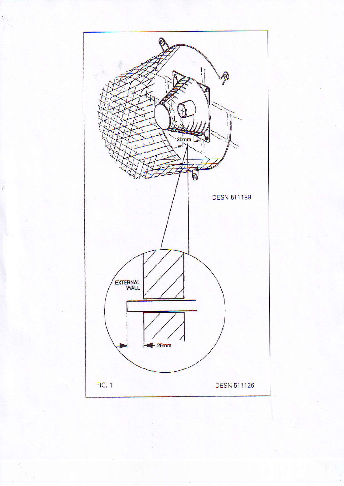
Products of combustion
metres
appliance can be
The vent
(19.5fr)
in length through a
pipe
should
discharge is by a fan
from rear L.H. or-R.H. sides, from the
exit through the outsrde
powered
Faximum
of 6 x 90' bends
wall fixing
pipe
vent
rear centre or
plate
50mm
or I metres
by 25mm
(2in)
diameter which can
(29ft)
with one
from the under side
(
1in) Fig. 1
bend Exits from the
(Figs.
2 & 3).
reach up to 6
DESN 511189
1
FIG,
DESN 511
126
rtt
el ffic{lrhl
S|l'E
EL
i f,ffi
gx
al'lr: ml
||!$ru
ffi.TD
tHtt^tsl
]
!t \rrfir ntr{N
o
off
xtE
||n/rdr*l
I L,'1: lSilr$d€l,M
I nE|,|n&
!3r
t'
Carejts|* t &€l rU rids
vArft !*hr&fig donlr6b. Wdng r.rq$ {3i
]rrpr.fllr
rawF
\is|ly
frsrnl
qrd
d!ng4|qf
{rr'ldrrt als $dr6s.
& *xs{ra$hn
ldar
cp!|q!rj
 Loading...