

Page 1

M F N-E- A2
Page 2

CONTENTS
CONTENTS
CONTENTS
CONTENTS
1. Products Introduction .................................................................................................................... 3
1.1. Specifications ..................................................................................................................... 3
1.2. Applications ........................................................................................................................ 4
1.3. System Requirements ......................................................................................................... 5
2. Interface & Installation .................................................................................................................. 5
2.1. Interface .............................................................................................................................. 6
2.2. I nstallation .......................................................................................................................... 7
2.2.1. Installation in LAN. ................................................................................................. 7
2.2.2. PPPoE Installation ................................................................................................... 8
2.2.3. IP Camera & P C connection .................................................................................... 9
3. IE Browse to IP Camera .............................................................................................................. 10
3.1. Use Finder ........................................................................................................................ 10
3.2. Logging and Active X I nstall ation ................................................................................... 11
3.3. Operation Keys ................................................................................................................. 13
3.3.1. Equipment Status ................................................................................................... 13
3.3.2. Administrator Operation ........................................................................................ 14
3.3.3. O perat ion ............................................................................................................... 15
3.4. Basic Setting s ................................................................................................................... 15
3.4.1. Device Information ................................................................................................ 16
3.4.2. Device Name Settings ............................................................................................ 16
3.4.3. Device Clock Setting s ............................................................................................ 16
3.4.4. Device User Settings .............................................................................................. 17
3.4. 5 . Basic Network Settings .......................................................................................... 17
3.4. 6 . Wireless LAN Settings .......................................................................................... 17
3.4. 7 . ADSL Settings ....................................................................................................... 18
3.4. 8 . UPnP Settings ........................................................................................................ 18
3.4. 9 . DDNS Settings ...................................................................................................... 18
3.4.1 0 . SMTP Settings ..................................................................................................... 19
3.4.1 1 . FTP Service Settings ............................................................................................ 20
3.4.1 2 . Alarm Service Settings ........................................................................................ 20
3.4.1 3 . Reset/ Firm Ware Upgrade ................................................................................... 21
3.4.14 Restore factory S etting s ........................................................................................ 21
3.4.15 Reboot E quipment ................................................................................................ 21
4.Central Management System ........................................................................................................ 22
5. Mobile Access ............................................................................................................................. 22
5 .1. Smart phon e Access .......................................................................................................... 22
6. Others .......................................................................................................................................... 25
6 .1. Port Forwarding S ettings in router ................................................................................... 25
6 . 2 . F series P roduct ion S pecification ( Part ) ..................................................................... 26
7 .Frequently Asked Questions ......................................................................................................... 27
8 . Warranty ...................................................................................................................................... 28
8 .1. Warranty Terms ................................................................................................................ 28
8 .2. W arranty C ard .................................................................................................................. 30
M F N-E- A2
- 2 -
Page 3

1.
Products
1.
Products
1.
1. Products
Products Introduction
An IP Camera is a new generation product combin ed with an analog camera & IP
v ideo technology . An IP camera has an analog camera’s full function, additionally it
can compress and encrypt video and audio signal through internet by sending them to
remote terminals with its built-in processor and web server. Via its IP address, users
can use standard PC IE browser to view IP camera and monitor targets in real time,
manage and store video or image. PTZ control is also available through network.
Being a new member of camera family, IP camera shares the same operation
function s with the analog camera, such as auto white balance, auto shutter speed ,
AGC, auto backlight compensation etc. On the other hand, IP camera supports remote
access through internet and multi-user visit. Some IP cameras are able to extend to
both analog and digital signal.
F series IP camera ‘ s core is 32Bit RSIC . It adopt s standard MJPEG compression
format. The camera sensor is CMOS which support s auto white balance and backlight
balance, support IE , cell phone browser , centralized monitor interface management. In
general, as its function of audio simplex & duplex, infrared, wired, wireless, POE,
PZT, local storage, it has hundreds of products, to meet requirements of various kinds
of users.
Introduction
Introduction
Introduction
1.1.
Specifications
1.1.
Specifications
1.1.
1.1. Specifications
Specifications
*- Adopt high Performance, strong function media processor 32Bit RSIC
*- High Sensitivity sensor CMOS
*- Adopt optimized MJPEG video compression algorithm, realize high-definition images
transmission in narrow bandwidth ;
*- S upport m aximum 5 users viewing at the same time, no limitation of users if using
Forwarder Server function ;
*- Built in Web Server , it is convenient for users to use standard browse to realize the
real time monitor ing and setting administration ;
*- Support WIFI: 802.11b/g wireless network ing;
*- Support remote system update ;
*- Support DDNS analysis, support LAN & Internet (ADSL
*- Support variety of network protocol: TCP/IP, UDP, SMTP, PPPoE, Dynamic
DNS, DNS Client, SNTP, BOOTP, DHCP, FTP, SNMP, WIFI/802. 11b/g
*- Selected mode l s support one/ two way audio talkback ;
*- Support Motion Detection alarm function (set area & sensitivity) ;
*- Support image snap
*- Abnormal automatic recovery function , if Network Interruption can auto
connection
*- Support mobile view
*- Some models support 15 preset positions and call preset positions when alarming
Cable Modem)
、
M F N-E- A2
- 3 -
Page 4

Image Compression Format Standard M-JPEG
Sensor
CMOS
300,000 pixel
,
Image Resolution Rate VGA ( 640x480 ) /QVGA ( 320x240 )
Network interface RJ-45/10-100 Base T , 802.11b/g
Network protocol TCP/IP,FTP ,SMTP,HTTP,UDP ,DHCP ,NTP,DDNS,UPNP ,D
NS,PPPOE
Image M ax T ransmission R ate
A lert control
30 frame/second
Output: 1 router ( 5VDC , 0.1A ) ; input: 1 router ( closure Trigger )
QVGA
(
, 15 frame/second
)
VGA
(
Motion Detection Support
Software U pdate Users automatically upgrade
Monitor Mode IE browse or special program
Playback Mode Microsoft Media Player
Security 3rd ranks password authority setting
M inimum illumination
2.0Lux@550nm
)
Auto White Balance Support
Working environment -10C °– 50C ° , 20% - 80% R H
Parameters F orm
1.2.
Applications
1.2.
Applications
1.2.
1.2. Applications
Applications
The series products usuall y can be applied to big department, supermarket, home,
factory, workshop etc.
- 4 -
Page 5

Untie the pack and check the items contained against the following list :
Wireless IP Camera …………………………………………………………………… 1
Wi-Fi Antenna ………………………………………………………………………… 1
DC Power Supply …………………………………………………………………… . 1
CD ………………………………………………………………………… . ……… ... 1
Manual ……………………………………………………………………………… .1
Mounting B racket …………………………………………………………………… . 1
Screws ………………………………………………………………………………… 2
NOTE: Contact us immediately in the case of any damaged or short of contents.
1.3.
System
1.3.
System
1.3.
1.3. System
System Requirements
Minimum H ardware C onfiguration
CPU: Pentium 1.6 GHz
Memory: 256MB
Audio card : need audio monitor, two way talk essential
Hard Disk : if need to record video image , no less than 40G
Operation System: 32 bit simple/ English Windows2000 、 Windows XP 、
Windows2003
Windows XP
Software environment
IE 5.0 or above version
DirectX8.0 or above version
TCP / IP network protocol
Requirements
Requirements
Requirements
Windows Vista & 64 bit simple Chinese/English Windows2003
、
Windows Vista etc.
、
、
2.
Interface
2.
Interface
2.
2. Interface
Interface &
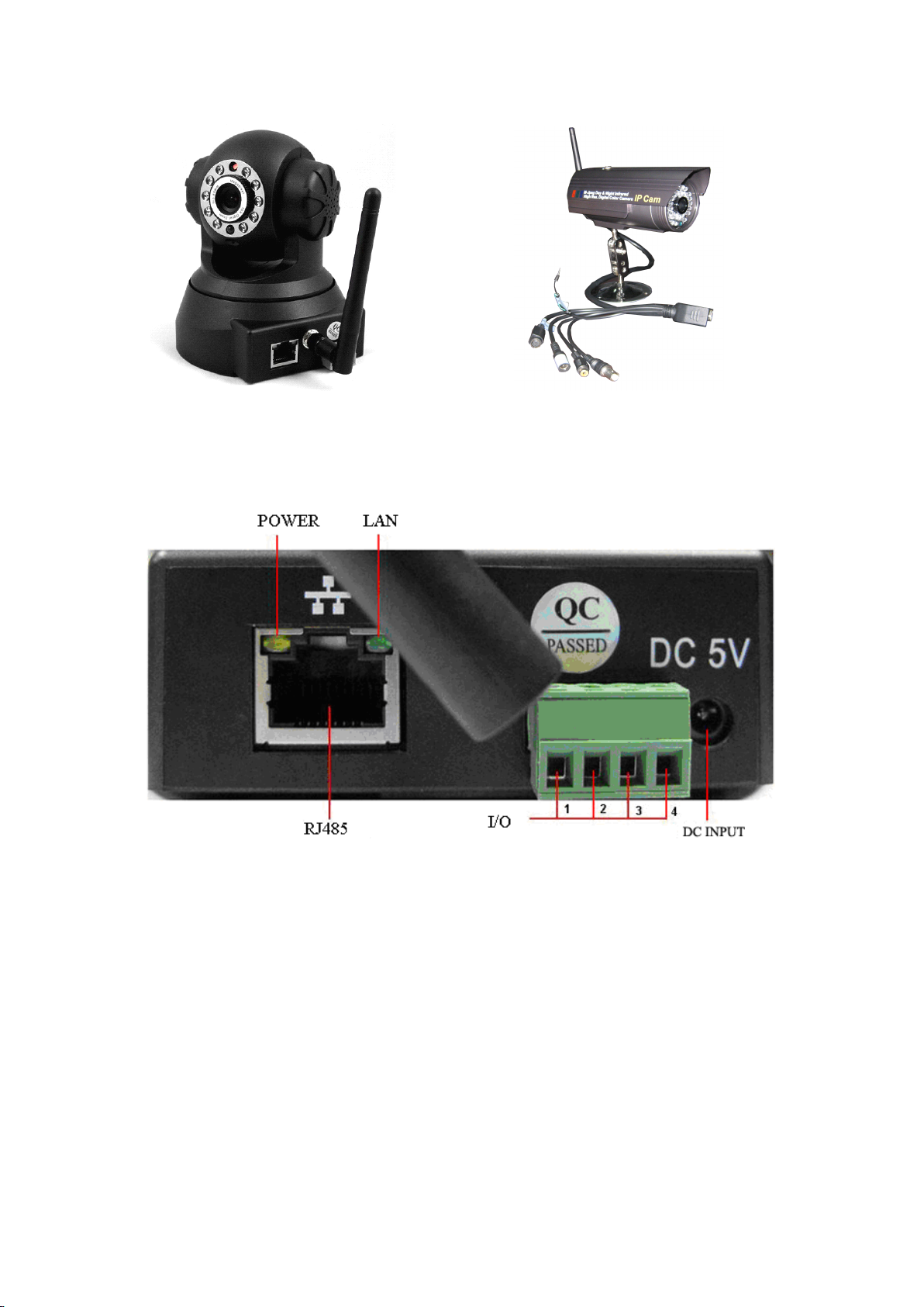
There are two kinds of interfaces for F series IP camera: one is body guard interface,
the other is the extend line interface . Here we give detailed explanations on two
representative products :
Non-extended line IP Camera icon E xtended line IP Camera icon
&
Installation
&
Installation
& Installation
Installation
-
M F N-E- A2
5
-
Page 6
2.1.
Interface
2.1.
Interface
2.1.
2.1. Interface
Interface
Non-extended line IP Camera Tailgate
Power S upply L ight: constant on when power is on
Network light: constant flash when power is on which shows data transmission.
Ethernet interface : RJ-45 interface.
I/O interface: 1 router alarm input, accept 3 , 4 two terminals (input terminal grounding ,
low level effective trigger); 1 router TTL control input, connect 1, 2 two
terminals (1, 2 terminals short connections).
Power input int erface: connect direct current 5V Power
Extension line interface definition icon:
Power: direct current 5V.
GPIO alarm interface: accept external connection linkage alarm equipment (for
example: door magnet, infrared)
Reset line: Short circuit two lines with power off, then power on for 10 seconds to
return back default setting
6
-
M F N-E- A2
-
Page 7

Ethernet interface: RJ-45 network interface.
Backup : follow-up product extend interface.
About GPIO alarm interface (S terminal) definition:
1# +DC12V
2# RS485 ( A )
3# Earth ( GND )
4# IO2
5# RS485 ( B )
6# IO1
GND: Ground
ground
RS485: RS485 control interface , left
connection RS485 negative right connection RS485 positive . connect P/T decoder ,
support variety PTZ protocol.
OUT PUT
(
IN PUT
(
alarm input ground
,
)
)
,
RS485
2.2.
I
nstallation
2.2.
I
nstallation
2.2.
2.2. I
I nstallation
nstallation
IP c amera process image transmission on the network through the us age of
Internet t echnolog
dialing users. IP Camera can connect to outer net through LAN, which can also be
connect ed directly.
There are 3 commonly used network connections in IP Camera:
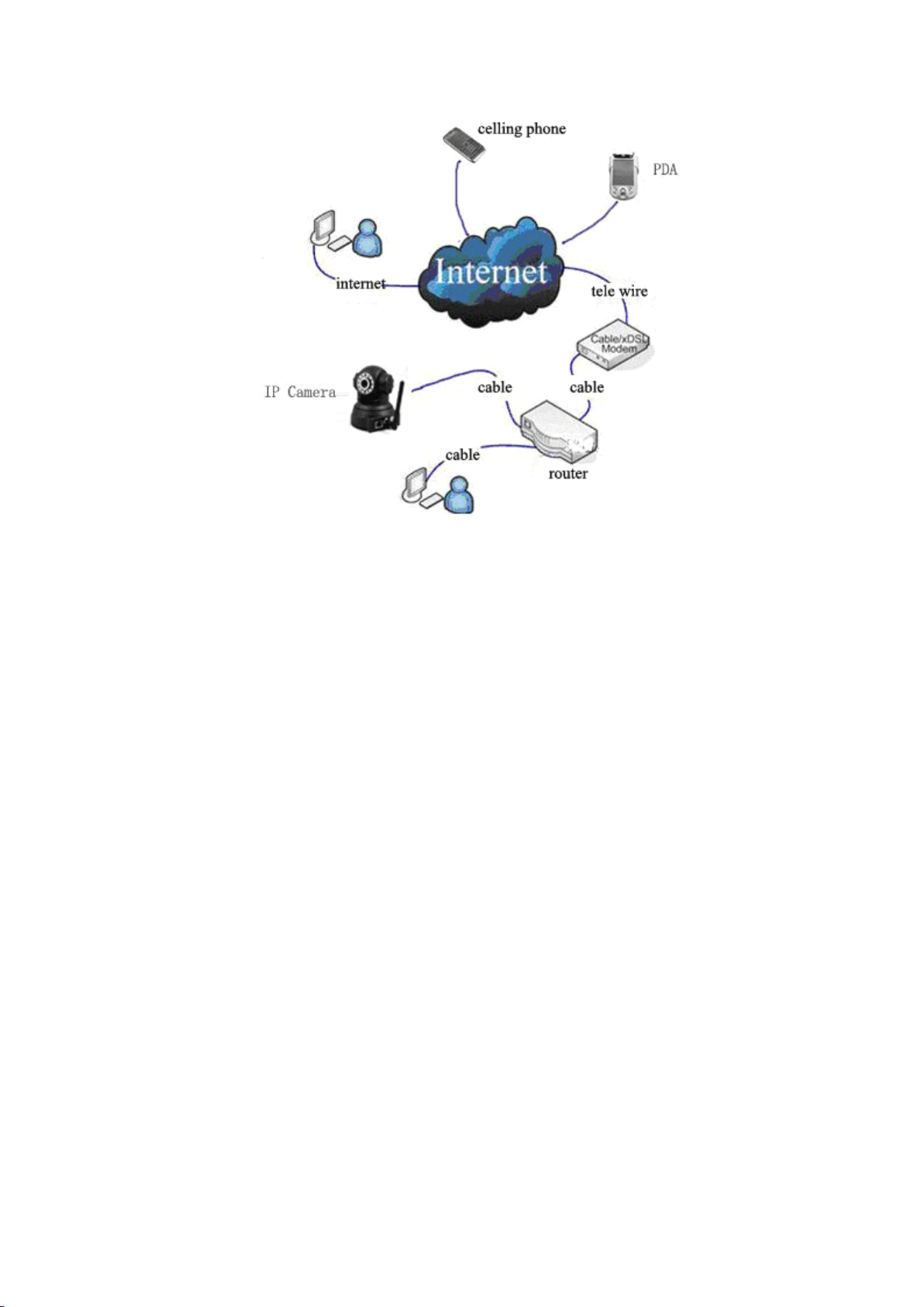
2.2.1. Installation in LAN.
This is the most popular network access method. As long as there is a router, using
internet cable directly connect router to IP Camera, then IP Camera can be connected
to Internet as normal PC, as showing in the following picture:
y,
which offers DDNS function for static
IP
, dynamic IP and PPPoE
M F N-E- A2
7
-
-
Page 8
2.2.2. PPPoE Installation
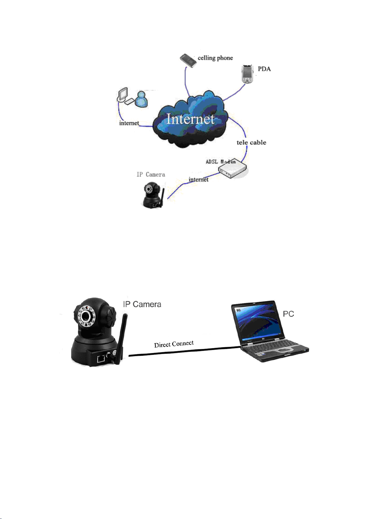
Under th is condition, users need to set up PPPoE dialing parameter in IP Camera:
input the username and password provided by ISP supplier ’ offer , this will allow the
IP Camera to connect to i nternet by dialing connects. As for set ting the PPPoE dialing
parameter, you can connect device to network through the first method , then write
parameter to the device , or through the following third method , direct ly write process
parameter to device . Please refer to 3.4.5. for detailed steps on how to set up PPPoE
M F N-E- A2
8
-
-
Page 9
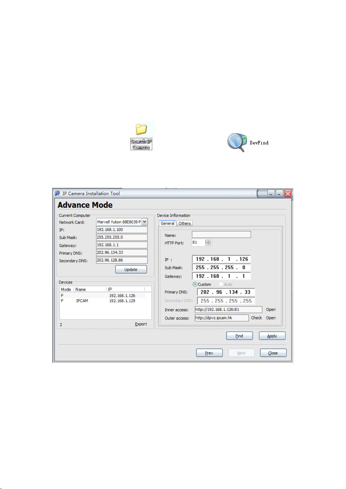
2.2.3. IP Camera & P C connection
T his method does not use frequently, when you process machine write parameter
or program shift, we suggest you to use the first connect network method to process
the modification of machine parameter.
connect power to IP camera (note : don ’ t apply for wrong power), after one
minute modification of IP camera, video could be connected via internet cable to IP
camera; under the normal condition, yellow light is on, green light flickers , now
physical connection of IP camera are finished. (In order to connect successfully, we
advise to set camera IP as the stable IP at the same net range of PC in LAN , please
refer to 8 frequent asked questions on how to set camera IP as the stable IP at the
same net range of PC in LAN).
M F N-E- A2
9
-
-
Page 10
3.
IE
3.
3.
3. IE
camera via PC, first please run the relative software in the CD kit
3.1.
3.1.
3.1.
3.1. Use
Open the disk, double click file , and double click search
bar icon will be found, double click search bar, then the f ollowing interface will
appear :
Browse
IE
Browse
IE Browse
Browse to
After IP camera connects to PC LAN through router, you can operate on IP
Use
Finder
Use
Finder
Use Finder
Finder
to
IP
to
IP
to IP
IP Camera
Camera
Camera
Camera
If the internet cable power connect is correct, it should show device styles, name,
and IP address in the device list, (if it dose not show, please confirm power & internet
cable connection).
For the interface, left side is the current computer configuration information;
right side is the selected device network configuration information. D efault IP camera
address will be set automatically according to the LAN , manually setting is not
needed(Note: DHCP should be opened in the router) , HTTP port is 81 .
Inner
Access
Inner
Access
Inner
Inner Access
Access refers to the LAN access address ;
;
Outer
;
Outer
; Outer
Outer Access
Access
Access
Access refers the WAN access
M F N-E- A2
10
-
-
Page 11
address.
B efore external net visit IP camera, port forwarding is necessary in the
Port
Forwarding
Port
senior router ,for more detail please refer to “ Port
router
router
router
router ” in 8.1 section.
Note
Note
Note
Note :
1. Device information indicates IP camera information.
2. When the current computer has a fixed
the IP camera is used for the first time, please click automatic
that IP address of the IP camera, gateway and DNS can be synchronous
with the PC.
3. .If it needs manually modify camera name, HTTP interface, IP
Forwarding
Port Forwarding
Forwarding Settings
IP,
(namely non-DHCP IP), and
automatic
automatic
automatic setup
Settings
Settings
Settings in
address, sub-net mask, gateway, main DNS server, backup DNS
server, etc. please click apply after modification, enter IP camera
username and password, click confirm.
setup
setup
setup , so
in
in
in
3.2.
Logging
3.2.
Logging
3.2.
3.2. Logging
Logging and
and
Active
and
Active
and Active
Active X
X
X
X I
I
nstall
I
nstall
I nstall
nstall ation
ation
ation
ation
Before IE monitoring through web, it is necessary to install a video plug-in, there
are 2 kinds of installation mode as shown below:
1. Open disk, file, double click inner , process installation,
th e installation process is as shown below:
a. Click the next step to continue
M F N-E- A2
11
-
-
Page 12
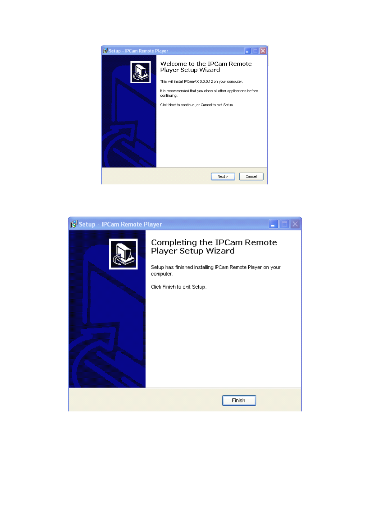
b. Click finish
2. Open web page , you can directly click open button which is behind inner visit
address or outer visit address in the search bar, also you can directly input relatively
inner and outer visit address in web page address bar such as: http: //192.168. 1 .126
LAN
(
, http: // dpvz .ipcam.hk
)
WAN
(
.
)
M F N-E- A2
12
-
-
Page 13
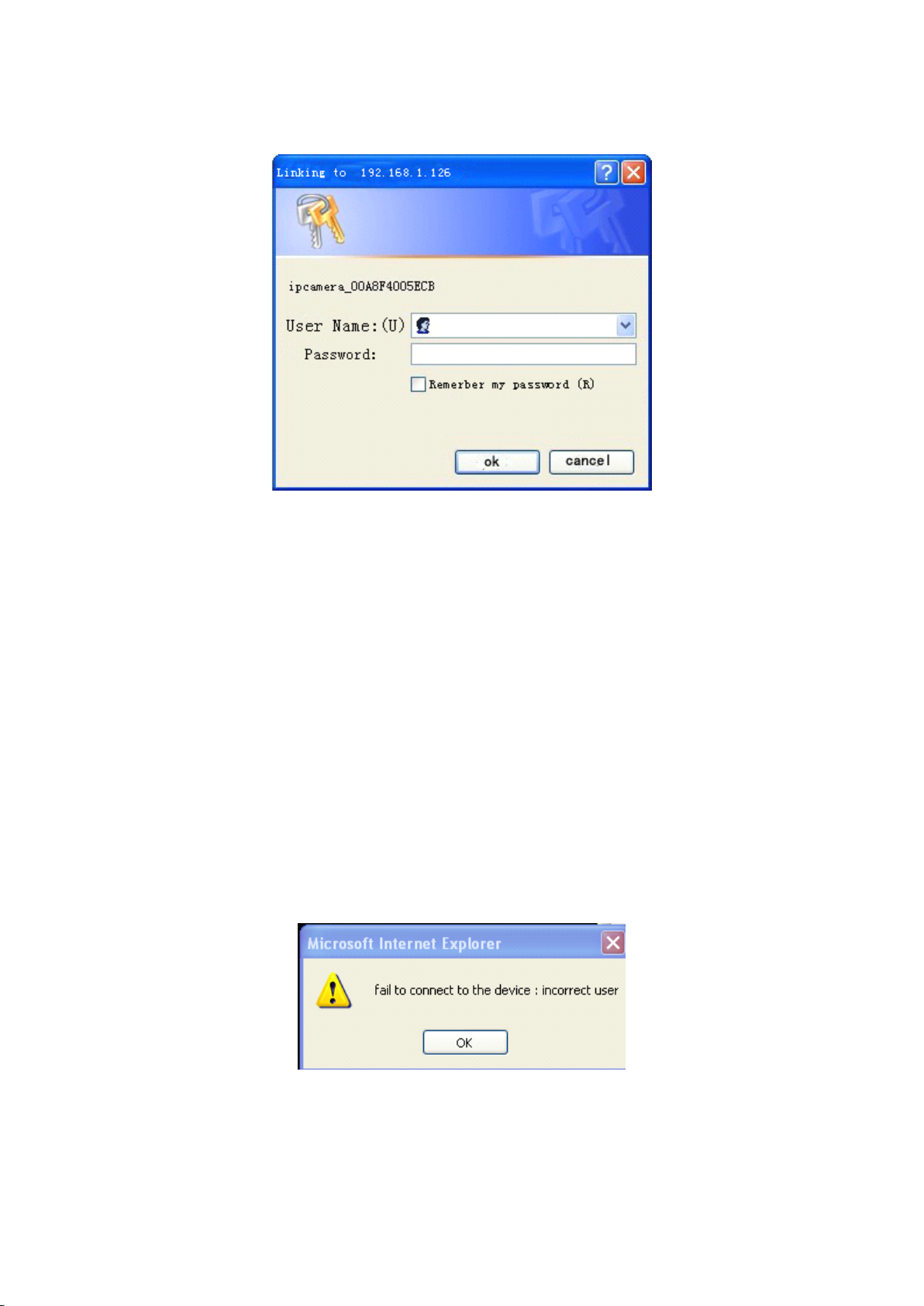
3. When the item connects to outer networking, a log-in interface will appear:
Enter log in information, click OK to enter, an installation pop-up will appear,
after installation is completed then you can use it. I f it is blocked and requires plug-in
installation by antivirus software, please remove block .
Note
:
Note
:
Note
Note :
:
1. Default device account is admin , no password.
2. M series IP camera doesn ’ t support Firefox browser , while F series support.
3.3.
Operation
3.3.
Operation
3.3.
3.3. Operation
Operation Keys
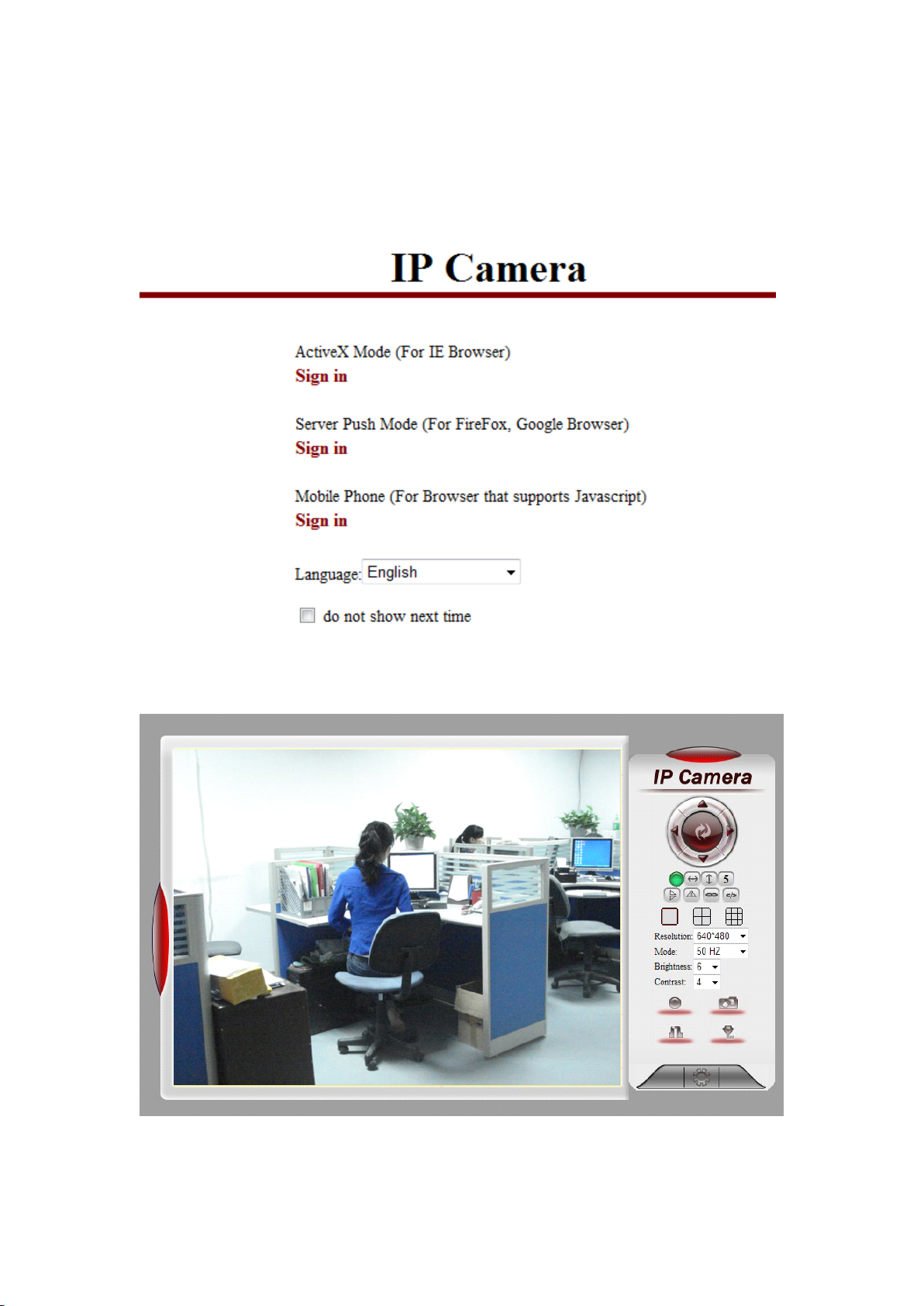
After sucesseful logging in, it displays monitor image on left side , and control
bottons used for operations on the right side:
3.3.1. Equipment Status
W hen login name or password is wrong , it will show the following hint:
Keys
Keys
Keys
M F N-E- A2
13
-
-
Page 14
3.3.2. Administrator Operation
Sign
in
Sign
Click Sign
in
Sign in
in , a pop-up will show , Sign in with ActiveX Mode(for IE)
M F N-E- A2
14
-
-
Page 15
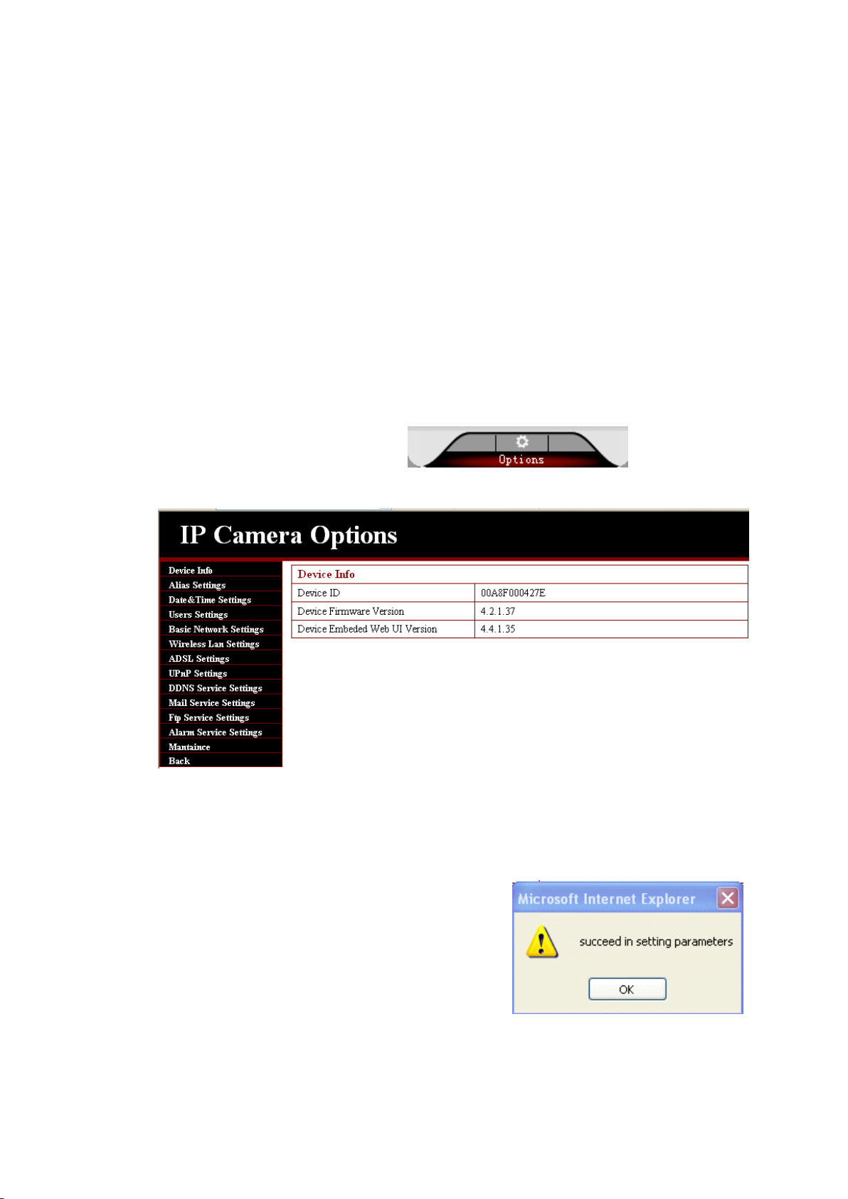
3.3.3. O perat ion
1. Image mirror indicates a reverse image.
2. Resolution, mode, brightness, contrast d efault setting are : 320*240 、 50HZ 、 6 、 4
mode is mainly for the adjustment of L ight strength, please adjust to 60HZ when
light is poor or in dark.
3. There are 3 browse modes in IE mode : visitor, operator, administrator . T he
authority of administrator is the highest . log in as different authorities , the o peration
will be different. Regarding to 3 user authorities , please refer to 3.4.4. Equipment
U ser A dministration.
3.4.
Basic
3.4.
Basic
3.4.
3.4. Basic
Basic Setting
parameter
Setting
Setting
Setting s
Click administration operation , enter the
s
s
s
,
Note: in basic setting, when you make a modification , please click setting. A hint
interface will pop up
1
the right interface will indicate
)
the parameter setting operation is s uccessful , p lease
click OK then r efresh .
2) the right interface will indicate the parameter
-
M F N-E- A2
15
-
Page 16
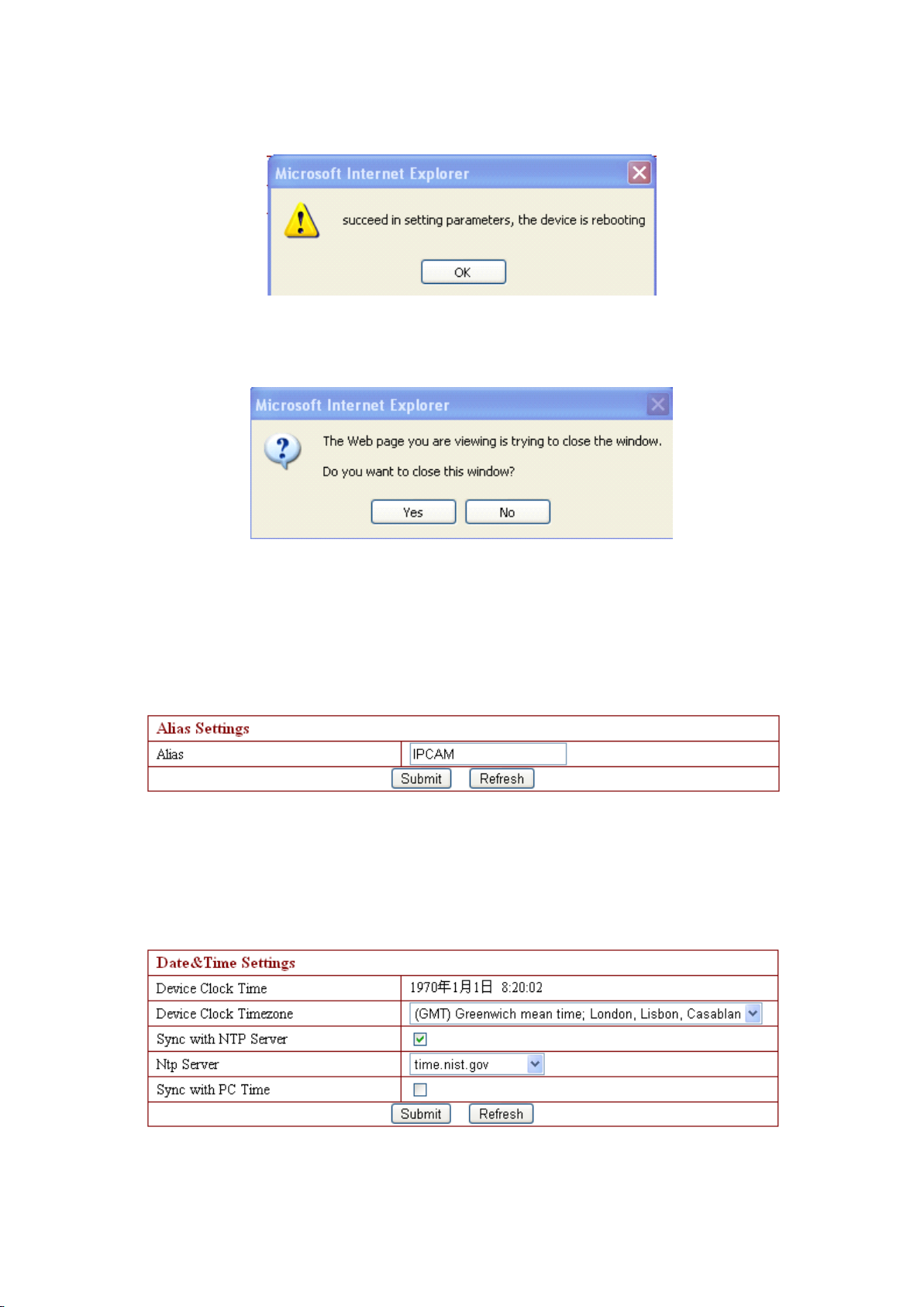
setting operation is successful, and need restart
to finish setting, please click OK.
If system indicates to restart (as right photo),
please single click yes (Y), and then enter again.
3.4.1. Device Information
The device information includes the above interfaces, device serial numbe r
MAC
(
3.4.2. Device Name Settings
Here the table displays camera name, such as the name search on search bar , the
name following mentioned as multiple channels equipments setting and so on .
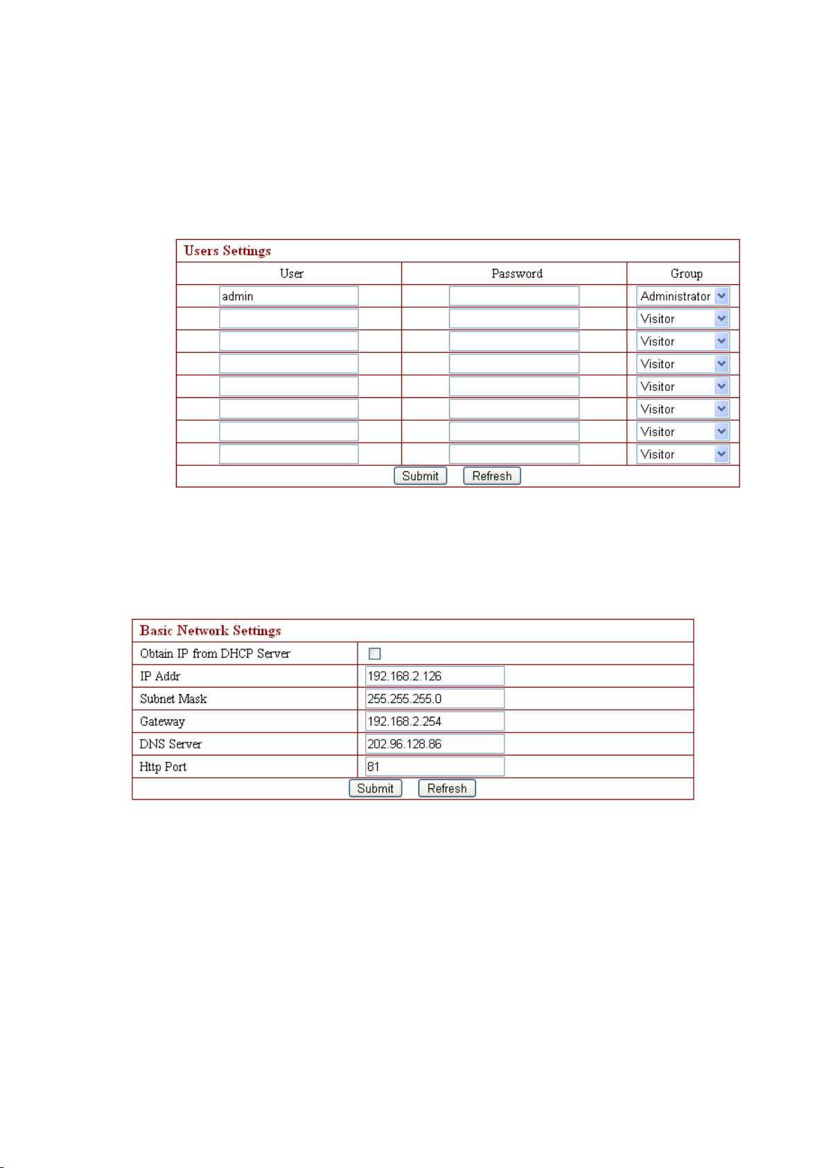
3.4.3. Device Clock Setting s
device system f irmware version, device application firmware version.
) 、
M F N-E- A2
16
-
-
Page 17
Y
ou can adjust time via NTP server or PC in this table.
3.4.4. Device User Settings
User can p roce ed with setting according to the interface as below . T he system is
available for administrator, operator, visitor whose authority are listed in order. .
N ote: At least one administrator is needed for the device;
3.4. 5 . Basic Network Settings
This sector is for DHCP and IP configuration. The port forwarding is needed, If
you want to set IP address , please fill in the relative IP address 、 s ubnet mask, gateway,
DNS server, Http port;
3.4. 6 . Wireless LAN Settings
M F N-E- A2
17
-
-
Page 18
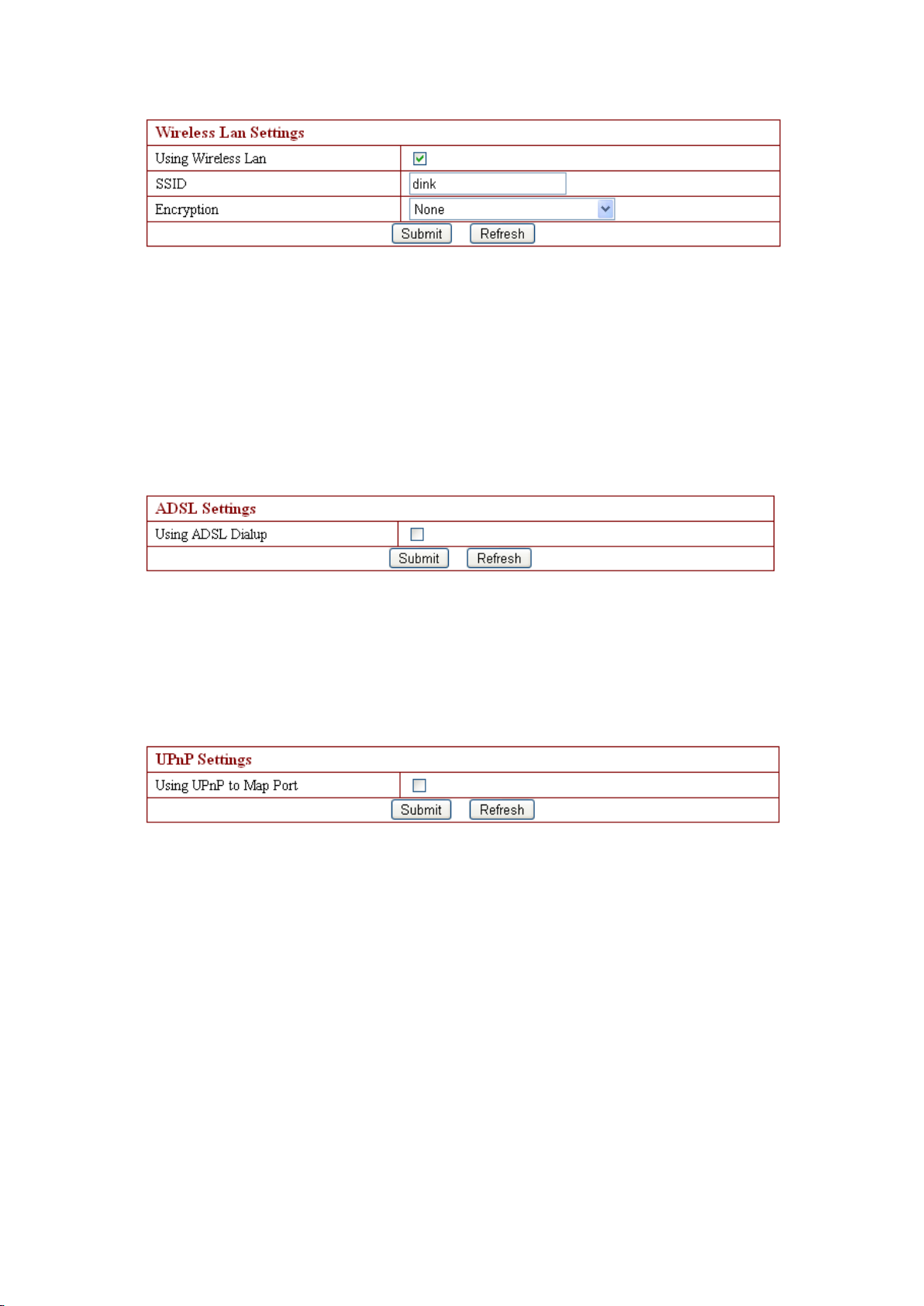
None,
Referring to the wireless networking s etting , there are 5 security modes: None,
WEP,
WEP,
WEP,
WEP, WPA
WAP2
WAP2
WAP2
WAP2 ( TKIP+AES
Note:
1. T o connect internet t hrough wireless network, the camera SSID number must be
2. Our default camera SSID number is dink.
3.4. 7 . ADSL Settings
While camera need s to be connected to ADSL directly , just tick the ADSL box to run,
then enter the ADSL user name and ADSL password which provide d by ISP (network
suppliers), and click to save ;
3.4. 8 . UPnP Settings
WPA
the same with the wireless router and other AP device SSID number,
Personal
WPA
Personal
WPA Personal
Personal ( TKIP ,
TKIP+AES
TKIP+AES
TKIP+AES ) .
TKIP,
TKIP,
TKIP, WPA
.
.
.
WPA
WPA
WPA Personal
Personal
Personal
Personal ( AES
AES
AES
AES ) ,
,
WPA2
,
WPA2
, WPA2
WPA2 Personal
Personal
Personal
Personal ( AES
None,
None,
AES
AES
AES ) and
and
and
and
The full name of UPnP is Universal Plug and Play, which is Plug_and_play . It is the
same saying as a utomatic port forwarding. If users need to use this function , router
must support this function and users just need to run it , then tick the above box;
3.4. 9 . DDNS Settings
18
-
M F N-E- A2
-
Page 19
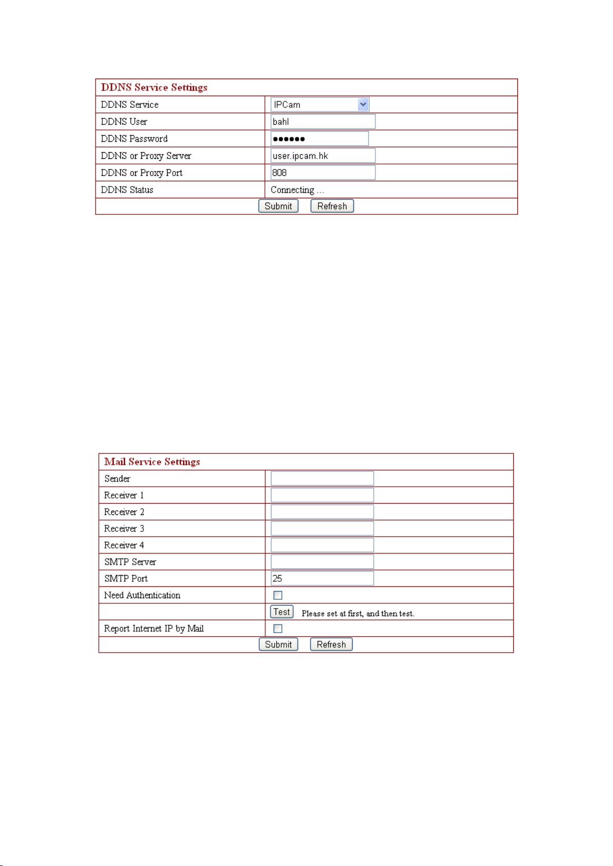
All the above information are set up when the device is ready. U sers generally do
not need to change. I n case of any accidental loss , user need s to re-obtain the domain
name, and fill it himself, juts do as the above , the user ’ s name is just the first four
characters , and this is for remote access. For example, http: //abcd.ipcam.hk, the
user ’ s name is abcd. The password is DDNS. (The password can be obtained on the
device body or contact the supplier) . When connected, it display s " xxxxx is OK" on
DDNS state; it means that it was successfully set. If you need to use your own
Dynamic DNS, please select the appropriate service providers ( on DDNS service)
then enter the following information , then save it;.
3.4.1 0 . SMTP Settings
The above setting is a preparation for the alarm function, the sender ’ s email
address should be entered by the sender , while the r ecipient E-mail address is filled in
by recipient 1,2,3,4. SMTP s erver should be filled in t he sender email SMTP s erver
for example t he sender email address is [email protected] , then here enter mail.163.com.
Generally SMTP port is 25
just tick it, and enter SMTP user name and SMTP password, which are provided by
no need to change. If the SMTP port required to check,
,
M F N-E- A2
19
-
,
-
Page 20
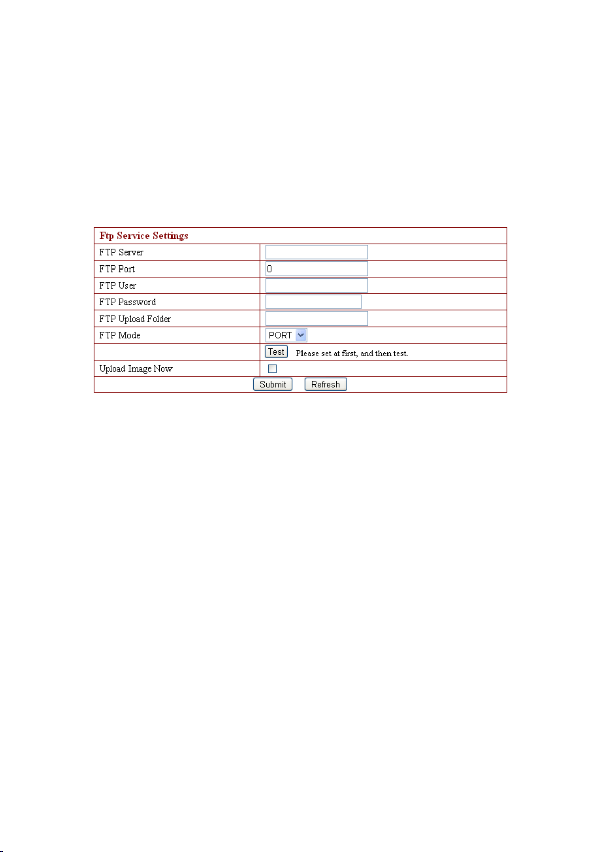
Email provider , then test according to reference. If report needs to send, please tick
report internet IP by Mail. The e-mail server and other information can be obtained
from the mail service provider . The email notifications are pictures captured by
camera when alarm is on. if no email notification is needed , there is no need to choose
this one..
3.4.1 1 . FTP Service Settings
Above setting is equally similar to Mail Server Settings
will send pictures
u pload directory and FTP mode. The FTP mode has two options : PORT and POSV.
If a quick upload picture is need , select Upload Image Now and change its interval
( second )。
3.4.1 2 . Alarm Service Settings
As shown below , there are two modes of a larm trigger . One is motion detection,
pleas refer to below interface
according to the users
is. Another one is input alarm, when connected, it triggers alarm t hrough alarm input
signal which connects to l inkage alarm GPIO ;
When triggered, there are 3 alarm modes: one is IO alarm linkage , camera
connects with l inkage alarm box through GPIO , sound the siren
notification , send email with images captured
way mentioned before FTP upload pictures alarm, U pload pictures interval(second
keeps consistent with the mentioned u pload pictures interval of Ftp service settings.
The s chedule refers to arming time
week to 0: 45 minutes and Monday 1: 00 hour and 2: 00 hour
please enter FTP server, FTP port, FTP user, FTP password, FTP
,
the s ensitivity of motion detect ion can be adjusted
,
requirement, t he higher the number is , the lower sensitivity
′
the last is upload pictures alarm
;
as the selected time interval: 0: 00 minute per
,
w hen alarm ing is on it
,
t he second is email
;
。
as the
,
)
M F N-E- A2
20
-
-
Page 21
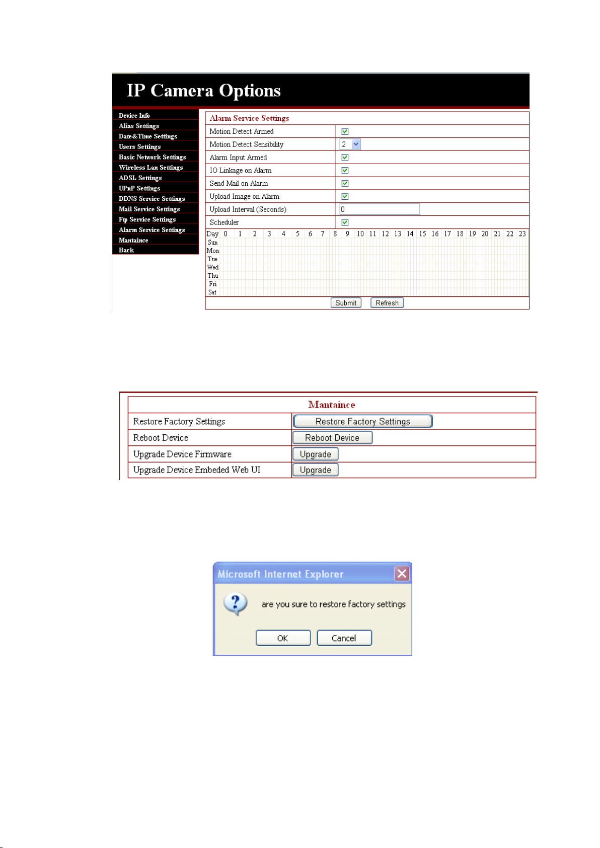
3.4.1 3 . Reset/ Firm Ware Upgrade
This sector is for camera firmware upgrade, it includes device system firmware
and device application firmware. Be careful to apply for it!
3.4.14 Restore factory S etting s
If users forget password, we c an restore ex- factory s ettings , when click the key , a
picture will pop up, Click ok , and wait for 1 minute then you can use it normally. U ser
s etting feature restores
3.4.15 Reboot E quipment
Click restart, it appears the below picture, click ok, wait for 1 minute and you can use it
M F N-E- A2
21
-
-
Page 22

normally .
4.
Central
4.
Central
4.
4. Central
Central Management
please refer to Central Management System User manual
5
.
Mobile
5
.
Mobile
5
5 .
. Mobile
Mobile Access
5
.1.
Smart
5
.1.
Smart
5
5 .1.
.1. Smart
Smart phon
Mobile and Symbian . D ue to its powerful function, the web page browser of such phones
usually supports Javascript. That ’ s why it can visit the dynamic pages of the IP camera
through web page browser.
First of all , the mobile phone must open internet access function .
Use the browser on the phone to visit the address of the IP camera, e.g.
http://demo.ipcam.hk ( “ demo ” is the Serial No. Each device has only one Serial No)
Next, taking the Opera mini 4 Version on Windows Mobile as an example, we are going
to introduce the whole procedure. E nter access address http://demo.ipcam.hk in the browser
address bar, the following interface will appear:
Management
Management
Management System
Access
Access
Access
phon
e
phon
phon e
T he smart phones are the mobile phones with operating system, such as Windows
Access
e
Access
e Access
Access
System
System
System
M F N-E- A2
22
-
-
Page 23
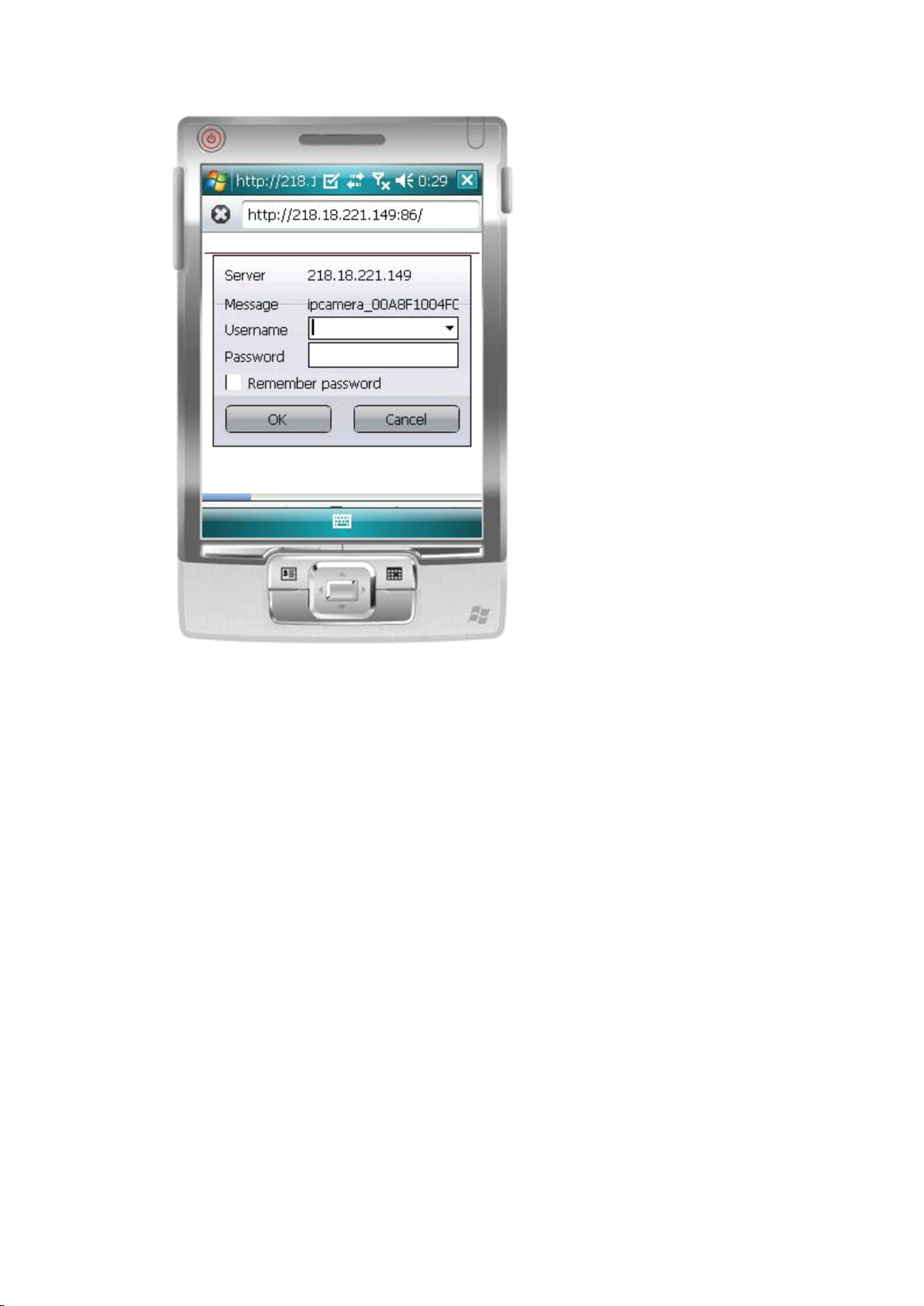
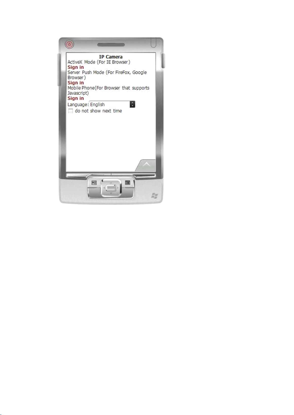
2. I nput the Username and Passoword of the device, and the following interface will
appear. T here are three log-in options. C lick on the third “ Sign in ” and use Mobile Phone
mode.
Language is used to select the display language.
Do not show next time : When this option is selected, this interface will not appear when you
log in next time. I t will directly skip to the monitor image..
M F N-E- A2
23
-
-
Page 24
D escription for the monitor image:
M F N-E- A2
24
-
-
Page 25
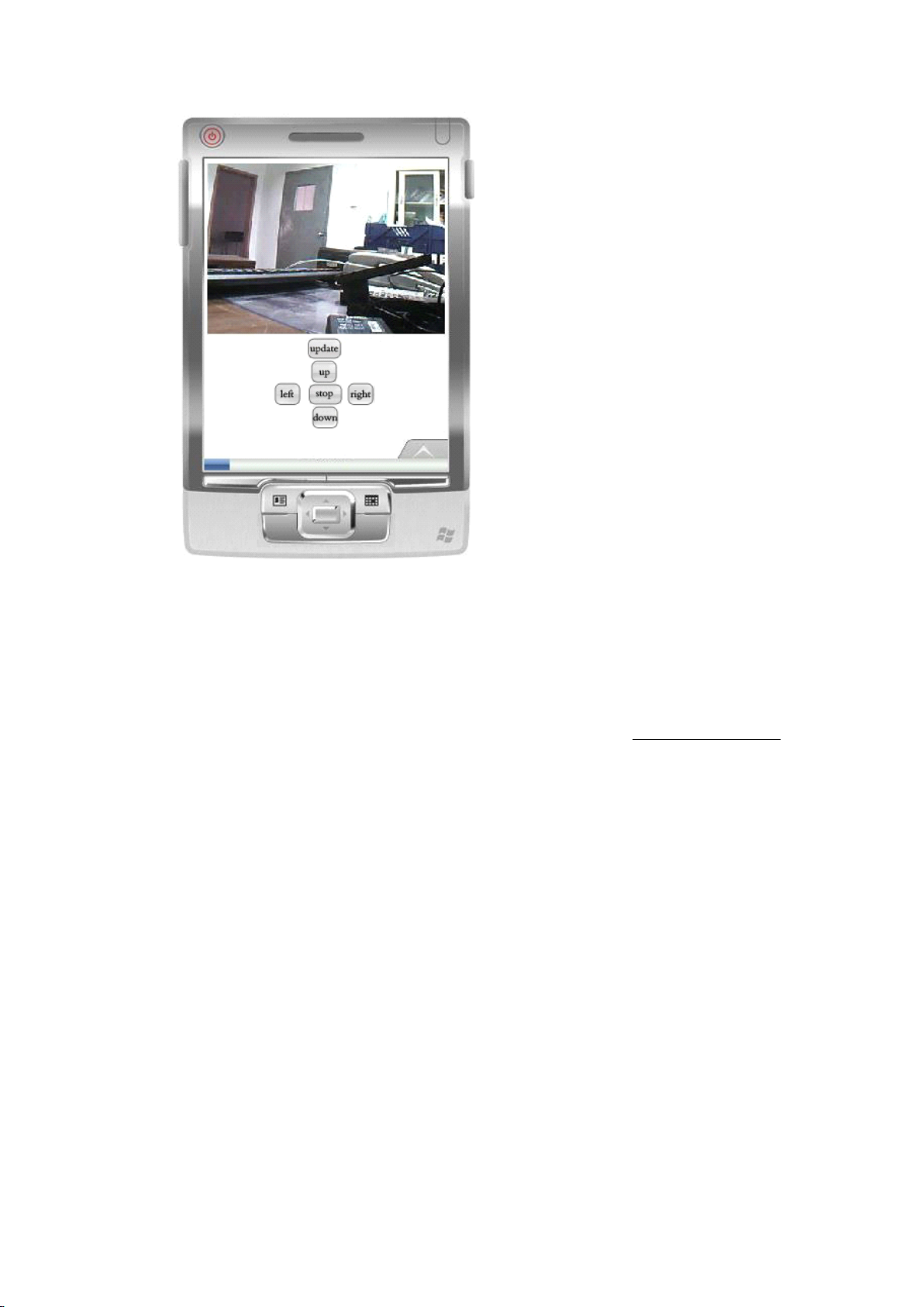
Instruction for the Key Function:
:
Update: it is used to refresh the page. I f the monitor piture is kept still, you may press this
key to update the page.
U p, down, left, and right: They are used to rotate the camera P/T. T he camera without P/T
does not have these keys.
S top: Stop to rotate the camera P/T
T he Download address of the mobile browser Opera mini: http://mini.opera.com .
Download the Opera mini browser according to the mobile model.
6
.
Others
6
.
Others
6
6 .
. Others
Others
6
.1.
Port
6
.1.
6
6 .1.
.1. Port
router is a needed. Different brands of routes called the port forwarding differently,
but basically their operation method are the same.
Router’s inner web IP address is 192.168.1.1, IP camera’s inner web address is
192.168.1.50 , and port is 85.
Forwarding
Port
Forwarding
Port Forwarding
Forwarding S
When users visit the IP camera via outside web, port forwarding settings in
Let’s take the TP-LINK TD-8840 router’s port mapping setting for example.
1. First log in router’s web administration interface.
2. Click “ Advanced Setup ” on the left side
S
ettings
S
ettings
S ettings
ettings in
in
router
in
router
in router
router
M F N-E- A2
25
-
-
Page 26
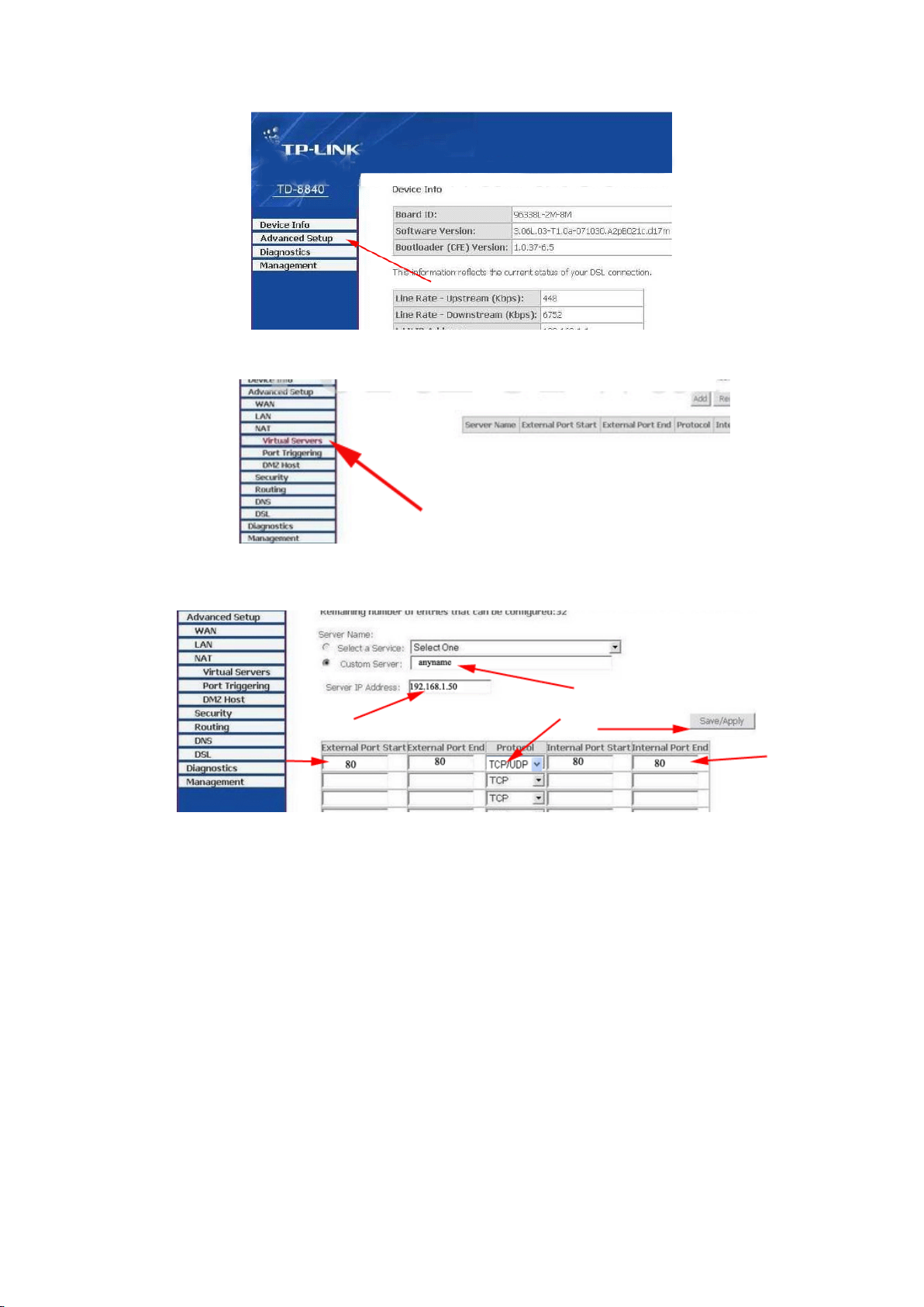
3. Click “ virtual server ” in the unfolded menu.
port
start
port
4. fill “ 80 ” under the right port
" 192.168.1.50 ", protocol select "TCP /UDP " OR ”
“ " save/apply ”
start
port start
start or port
port
port
port end
TCP
“
end
Server
end
Server
end , Server
Server IP
, finally don ’ t forget to click
”
IP
address
IP
address
IP address
address fill
D etailed information please refers to following photo: When completed port
forwarding, you can visit camera through device code in outer net remotely;
Common router default visit address are as follow:
1. DLINK ex-factory definition router address is 192.168.0.1
2. Linksys ex-factory definition router address is 192.168.1.1
3. 3com ex-factory definition router address is 192.168.2.1
4. Microsoft ex-factory definition router address is 192.168.2.1
5. Net gear ex-factory definition router address is 192.168.1.1
6. Asus ex-factory definition router address is 192.168.1.1
6
.
2
.
F
.
2
. 2
2 .
.
F
. F
F series
series
series
series P
6
6
6 .
Th is series produce own variety c onfigured specification . Users can choose the best
P
roduct
P
roduct
P roduct
roduct ion
ion
ion
ion S
S
pecification
S
pecification
S pecification
pecification
Part
Part
(
(
(
(
Part
Part
)
)
)
)
26
-
M F N-E- A2
-
Page 27
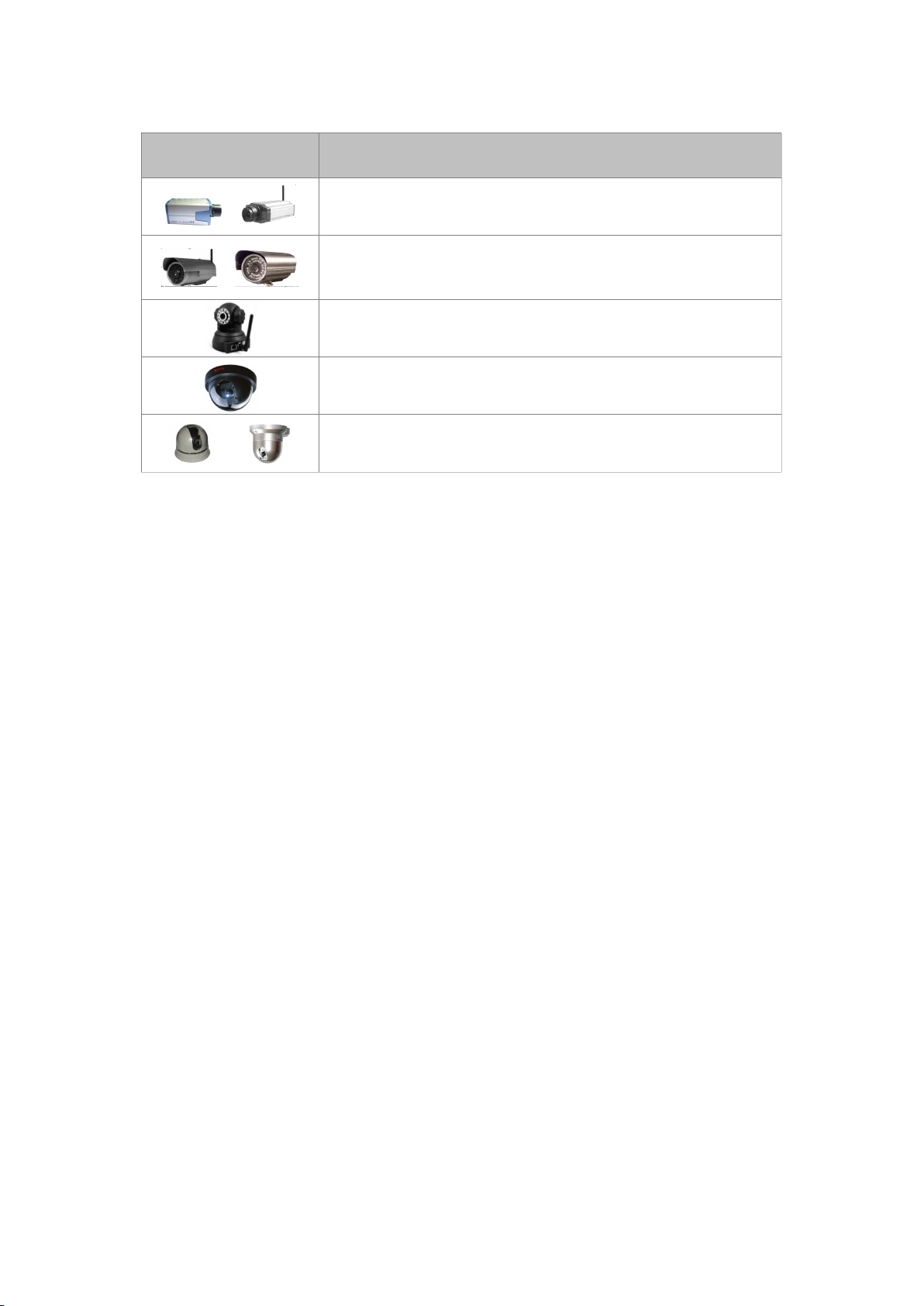
one according to their requirement. .
Image Specification
Bullet camera , wired/ wireless selected, indoor
Infrared bullet camera wired/wireless selected, infrared
20m/40/50m selected indoor/waterproof selected lightning
protection design
Wired/Wireless selected, infrared 10 m Audio selected
Level & vertical rotation P/T
Cell indoor select infrared night vision 20 m
Cell indoor overall rotation P/T 5 ” or 3.5 ” mini dome,
audio selected
7
.Frequently
7
.Frequently
7
7 .Frequently
.Frequently Asked
Asked
Asked
Asked Questions
Questions
Questions
Questions
Question : Why can not I find ou r camera us ing search bar ?
Answer: 1. Please checks whether IP camera and search bar be located in the same
LAN network;
2. Maybe the problems of Internet cable or power connection 【 Under normal
circumstances
constant sparkle 】
3. Whether there is a firewall installed in the computer.
Question : Do F series products support P2P technology ?
Answer: Yes. Users could visit it by centralized management interface or platform to
realize P2P visit. Applying P2P technology can solve the problems raised
by multiple users visit one IP camera at the same time , which is mainly b/c
the network technology allow users to s hare IP camera video data.
Question: What is the max piece number that F series motion detection area
support?
Answer: F series support 1 piece motion detection area, which is a whole image.
Question : Do the F series product allow the users to browse dynamic video through
cell phone?
Answer: Yes, but only the cell phone which supports JAVA can.
, power light (yellow) constant on, network light (green)
Question : Where can we download cell phone visiting program?
Answer: Please refer to the first chapter of help text of cell phone visiting.
Question : Does centralized monitor interface support Vista & Linux system ?
M F N-E- A2
27
-
-
Page 28

Answer: Just Vista system. Right now it do not support Linux system.
Question : How to set IP camera the same network segmen t as PC in LAN
Answer: First you can u se search bar to find out the camera, then click auto set button.
Question : What mode of cell phone does the F series camera allow to visit ?
Answer: Generally, cell phone with Java MIDP 2.0 program can watch dynamic
video.
Curren tly, confirmed cell phone modes are NOKIA E71 , 6122C MOTO
A3000 , NOKIA N70-73 N95 N98 , Samsung U608 etc.
Question : why the cell phone software can ’ t visit IP camera ?
Answer: 1. Please check whether cell phone support Java program
2. Whether the cell phone open WAP function, and set WAP factors
c orrectly . .
3. Make sure that IP camera can be visited through the internet;
Question : Why IP camera ’ s image is too white or too dark.
Answer: Open IP camera interface, try to modify camera mode.
;
8
.
Warranty
8
.
Warranty
8
8 .
. Warranty
Warranty
In the period of warranty , any breakage resulting from products ‘ own failures .
Users will be free of charge of its maintenance .
8
.1.
Warranty
8
.1.
Warranty
8
8 .1.
.1. Warranty
Warranty Terms
a) F ree - Charge maintenance period of the product is one year , during this time;
w e can repair it for free ( Damages not caused by misuse or vandalism ).
Repair over guarantee period, we will charge maintenance fee .
b) During guarantee period, breakdown caused by misuse or other reasons out of
range of warranty. Users c an repair it by showing th is card.
c omponents .
c) When the products need maintenance, hand up the card with products to the
manufacture or local d istribut or.
d) Tak ing apart item crust and tear ing up the sealing label privately is out of
warranty range.
e)
We
functions.
Terms
Terms
Terms
We
only charge for
do not repair the damaged item due to modification or add other
Under t he F ollowing C ircumstances , the maintenance will be charged:
a) P eriod check, maintenance or chang e components due to no rmal attrition .
b) T he damages due to crash , extrusion , artificial flooding , m oisture or other
personal reasons.
M F N-E- A2
28
-
-
Page 29

c) The damages due to floods , fire, lightning strike and other natural calamities
or force majored incidents factors
d) Repaired item by non-authorized repair centers .
All above terms, if these is any changes; they should according to relevant
regulations .
M F N-E- A2
29
-
-
Page 30

8
.2.
W
8
8
8 .2.
Manufacturing Date : Product Specification :
Inspector :
Version number :
arranty
.2.
W
arranty
.2. W
W arranty
arranty C
Product Model
Sale Dates
User Company
User name
Customer Address
C
C
C ard
ard
ard
ard
Contact Number
Maintain Date Failure Conditions
Remark :
Note: please fill the card and offer it with products if guarantee of repair
Results of
Maintenance
M F N-E- A2
30
-
-
 Loading...