

Agasio A621W User Manual
IP Wireless / Wired Camera
REMOTE PAN/TILT ROTATE
User Manual

MoreSecurity,MoreConvenience
CONTENTS
1 WELCOME ......................................................................................................................................................3
1.1 FEATURES................................................................................................................................................................................................ 3
1.2 PACKING LIST.......................................................................................................................................................................................... 3
1.3 PRODUCT VIEWS .....................................................................................................................................................................................4
1.4 PC SYSTEM REQUIREMENTS ................................................................................................................................................................... 5
1.5 HARDWARE INSTRUCTION ....................................................................................................................................................................... 5
1.6 SOFTWARE INSTALLATION .......................................................................................................................................................................5
2. SOFTWARE OPERATION.............................................................................................................................. 7
2.1 IP CAMERA TOOL.................................................................................................................................................................................... 7
2.2 CAMERA LOGIN..................................................................................................................................................................................... 10
2.3 FOR IE BROWSER.................................................................................................................................................................................. 12
2.4 FOR SAFARI, FIREFOX, GOOGLE BROWSER ........................................................................................................................................... 14
2.5 FOR MOBILE PHONE..............................................................................................................................................................................15
2.6 ACTIVEX MODE (FOR IE BROWSER)..................................................................................................................................................... 15
2.7 FOR VISITOR..........................................................................................................................................................................................15
2.8 FOR OPERATOR......................................................................................................................................................................................19
2.9 FOR ADMINISTRATOR ............................................................................................................................................................................21
3 SETTINGS AS ADMINISTRATOR ................................................................................................................21
3.1 MULTI-DEVICE SETTINGS......................................................................................................................................................................22
3.2 NETWORK SETTINGS .............................................................................................................................................................................27
3.3 BASIC NETWORK SETTINGS................................................................................................................................................................... 27
3.4 WIRELESS LAN SETTINGS...................................................................................................................................................................... 29
3.5 ADSL SETTINGS.................................................................................................................................................................................... 31
3.6 UPNP SETTINGS .................................................................................................................................................................................... 31
3.7 DDNS SERVICE SETTINGS.....................................................................................................................................................................31
3.8 SYSTEM SETTINGS.................................................................................................................................................................................35
3.9 ALIAS SETTINGS....................................................................................................................................................................................36
3.10 DATE &TIME SETTINGS....................................................................................................................................................................... 36
3.11 USERS SETTINGS .................................................................................................................................................................................37
3.12 PTZ SETTINGS..................................................................................................................................................................................... 38
3.13 INDICATOR SETTINGS ..........................................................................................................................................................................38
3.14 BACKUP & RESTORE ........................................................................................................................................................................... 38
3.15 OTHER SETTINGS................................................................................................................................................................................. 40
3.16 MAIL SERVICE SETTINGS.....................................................................................................................................................................40
3.17 FTP SERVICE SETTINGS....................................................................................................................................................................... 42
3.18 ALARM SERVICE SETTINGS..................................................................................................................................................................43
3.19 SEND MAIL ON ALARM........................................................................................................................................................................46
3.20 PATH SETTINGS.................................................................................................................................................................................... 48
3.21 SERVER PUSH MODE (FOR SAFARI, FIREFOX, GOOGLE BROWSER).....................................................................................................49
3.22 SIGN IN MOBILE PHONE........................................................................................................................................................................ 49
4. APPENDIX....................................................................................................................................................50
4.1 FREQUENTLY ASKED QUESTIONS .......................................................................................................................................................... 50
4.2 DEFAULT PARAMETERS..........................................................................................................................................................................53
5. SPECIFICATIONS ........................................................................................................................................53
6. OBTAINING TECHNICAL SUPPORT..........................................................................................................54
2

MoreSecurity,MoreConvenience
1 WELCOME
This is an integrated wireless IP Camera solution. It combines a high quality digital Video Camera with network
connectivity and a powerful web server to bring clear to your Desktop from anywhere on your local network or
over the Internet.
The basic function of it is transmitting remote video on IP network. The high quality video image can be
transmitted with 30fps speed on the LAN/WAN by using MJPEG hardware compression technology.
It is based on TCP/IP standard, build-in WEB server which could support Internet Explorer. Therefore the
management and maintenance of your device become easier by using network to achieve the remote
configuration, start-up and upgrade firmware.
You can use this IP Camera to monitor some special places such as your home and your office. Also
controlling and managing images are easy by clicking the website through the network
.
1.1 Features
☆Powerful high-speed video protocol processor
☆High-sensitivity 1/4’’ CMOS sensor
☆Picture total 300k pixels
☆Support 3x Optical Zoom
☆Support PT control, Pan 355°, Tilt 90°
☆Optimize MJPEG video compression for transmission
☆Multi-level users’ management and passwords definition
☆Embed Web Server for users to visit by IE
☆Support wireless network (WI-FI/802.11/b/g)
☆Support Dynamic IP (DDNS) and UPNP LAN and Internet (ADSL, Cable Modem)
☆Give alarm in cause of motion detection
☆Support image snapshot
☆Support multiple protocols:HTTP/TCP/IP/UDP/SMTP/DDNS/SNTP/DHCP/FTP
☆Support WEP/WPA/WPA2 encryption
☆Support 3G phone, Smart phone control and surveillance
☆Support Firefox, Safari, Google chrome browser.
1.2 Packing List
Untie the pack and check the items contained against the following list:
●IP Camera X1
●Wi-Fi Antenna X1 (only available for wireless model)
●User Manual X1
●DC Power Supply X1
●CD X1
●Network Cable X1
●Mounting bracket X1
NOTE: Please contact us immediately if anything damaged or short of contents.
3
1.3 Product Views
1.3.1 Front View
MoreSecurity,MoreConvenience
Figure 1.1
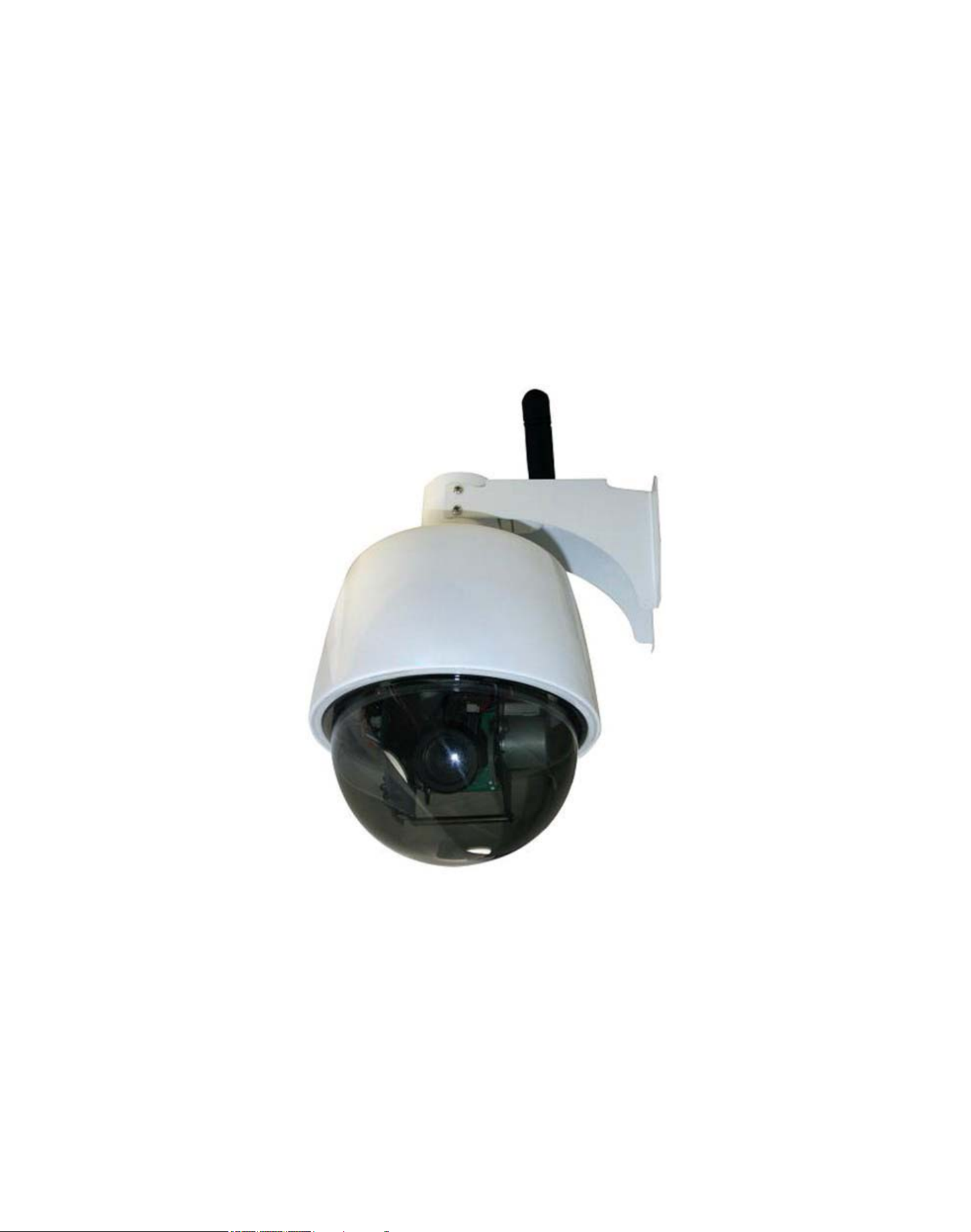
1 LENS: CMOS sensor with fixed zoom lens.
2 Housing: Alloy housing for waterproof
3 Wireless Antenna: WI-FI Antenna (For wireless model only)
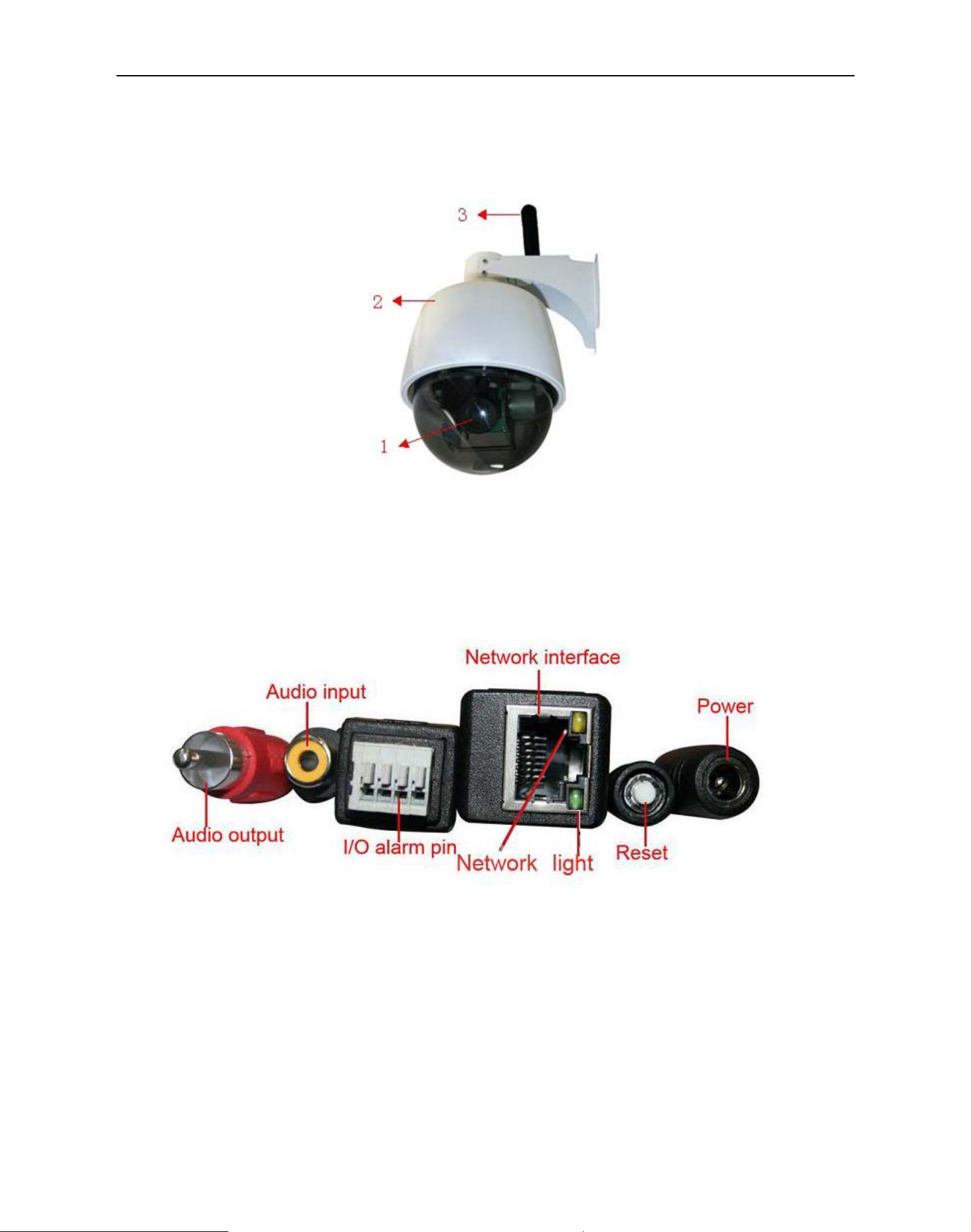
1.3.2 Cable Interface
Figure 1.2
Audio Output: The jack is used to plug external speaker or audio output device.
Audio Input: The jack is used to plug external microphone or audio input device.
I/O Alarm Pin: 1 Alarm input(GND) 2 Input 3 Output A 4 Output B
Network Interface: RJ-45/10-100 base T
Network Light: The green LED will on when network connected, the yellow LED will blink when data
transferred
Reset: Press and hold the RESET button for about 15 seconds, all the parameters will be back to the factory
default settings. (Please keep the power on when do RESET)
Power: DC 12V/2A power supply
4
MoreSecurity,MoreConvenience
1.4 PC System Requirements
System configuration requirements :( Example for viewing four IPCAM)
CPU: 2.06GHZ or above
Memory: 256M or above
Network Card: 10M or above
Display Card: 64M or above memory
Recommendable Operating system: Windows 2000/ XP/ Vista/ 7
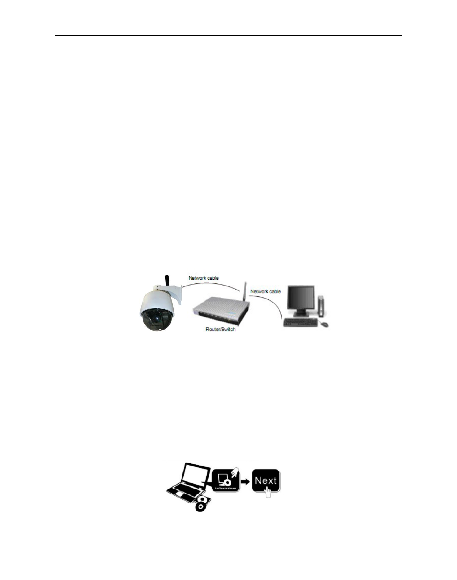
1.5 Hardware Instruction
Follow the steps below to set up your camera hardware. Make sure to follow each step carefully to ensure that
the camera operates properly
1. Install the Wi-Fi antenna(For wireless model)
2. Plug the power adaptor into camera
3. Plug the network cable into camera and router/switch
4. It takes approx 30 seconds to boot up the camera, then you will find the IP address from
“IP Camera Tool” (Figure: 1.8)
5. When the power on and network cable connected, the green led of the real panel will keep on,
The yellow led will keep flash.
Figure1.3
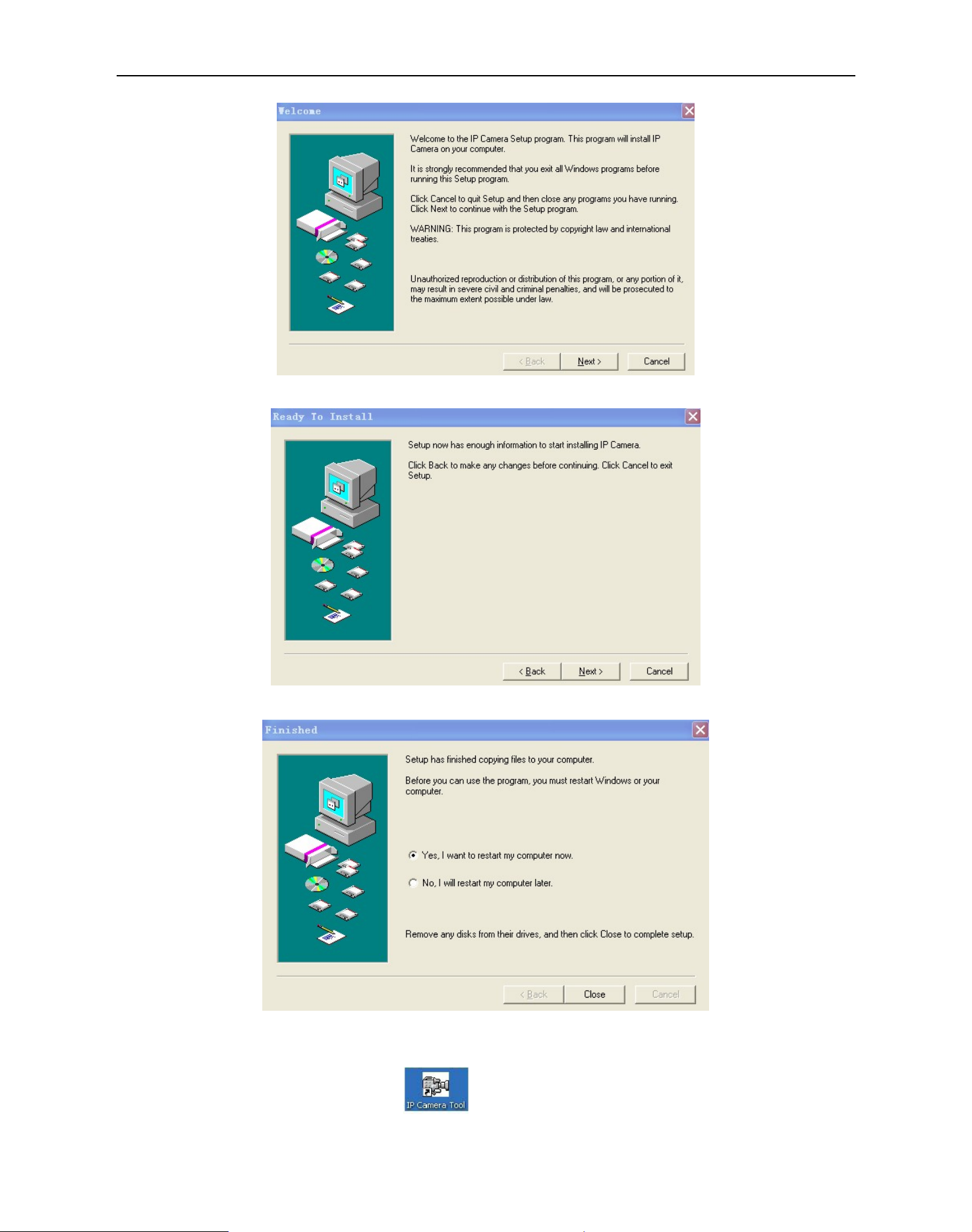
1.6 Software Installation
Attention: In order to make the installation correctly, we suggest that turn off your Firewall and Antivirus before
install the ActiveX, Don’t worry, it is safe. (If you are Windows 7 User, please run as administrator)
Software installation is the key to the successful use of this product.
Install the follow software:
1. IP Camera Tool: Open the CD, dbclick “IPCamSetup.exe”, only click next, you will complete the software
installation.(figure1.5/ 1.6/ 1.7)
2. ActiveX: Double click “Appinstall.exe”—“Next”—“Install”—“Finish”.
Figure1.4
5
MoreSecurity,MoreConvenience
Figure1.5
Figure1.6
Figure1.7
After this done, the icon “IP Camera Tool” will be displayed on desktop automatically.
6
MoreSecurity,MoreConvenience
CAUTION: Before installing and using the product, please read the following precautions carefully and make
sure they are fully understood.
Use only the power adaptor attached with the product. Use unauthorized power adapter may cause damage to
your IP Camera.
Do not touch the lens of the IP Camera at will. The optimum focus range has been set before it is delivered out
of the factory. If you turn the lens, it may cause incorrect focus and vague images.
Do not turn the Pan/Tilt by force, it may cause damage to internal components of the Pan/Tilt.
For firmware upgrading or connection with an external, refer to detailed instructions contained in the CD.
2. SOFTWARE OPERATION
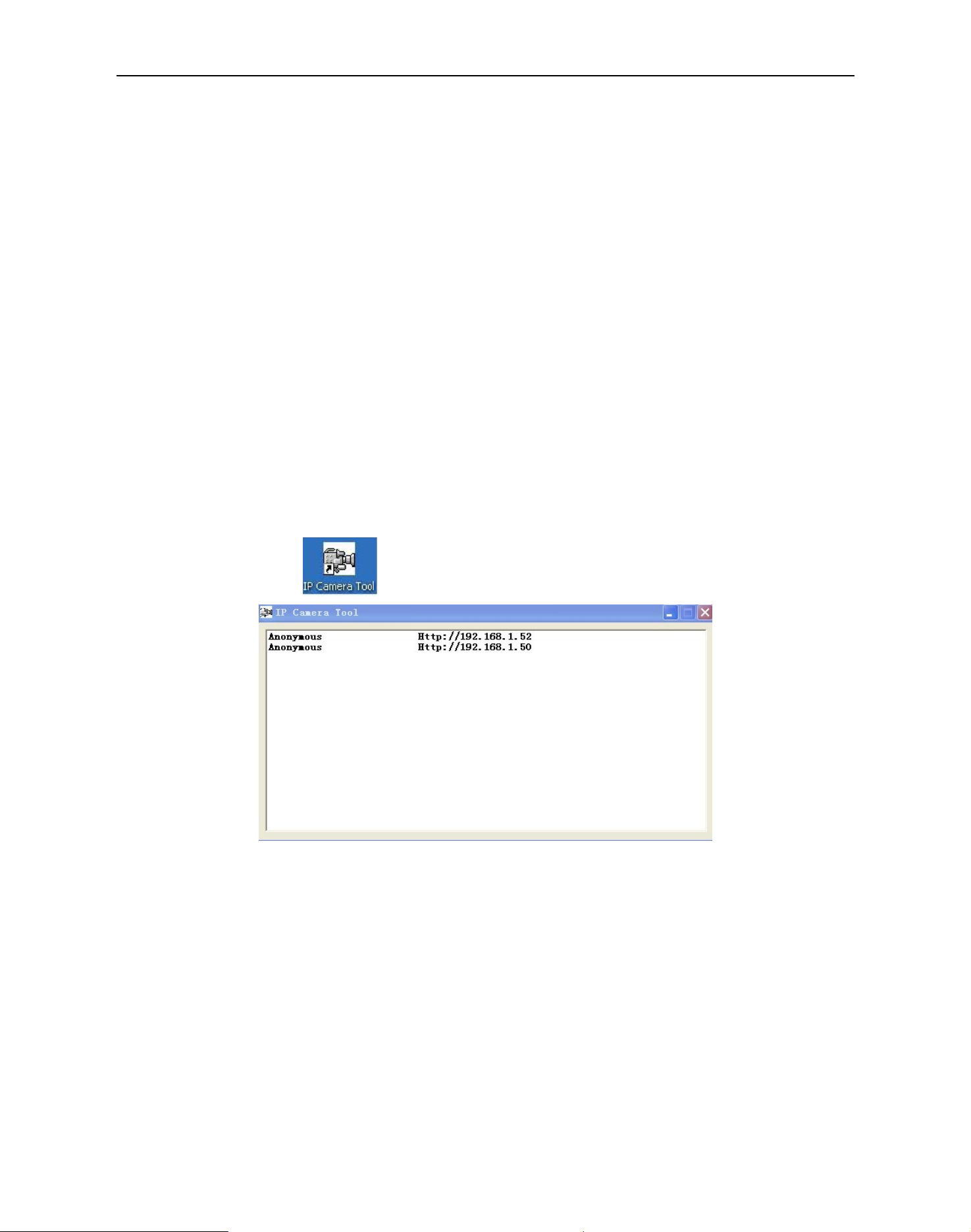
2.1 IP Camera Tool
When the Device has been mounted properly, you can double click the Icon “IP Camera Tool”
and a dialog box as Figure 1.8 will pop up.
Figure1.8
Note: The software searches IP Servers automatically over LAN.
There are 3 cases:
1. No IP Cameras found within LAN. After about 1 minute search, the Result Field will show “not found IP
Server” and the program shut automatically.
2. IP Cameras have been installed within LAN. All the IP Cameras will be listed and the total number is
displayed in the result field as shown in Figure 1.8
3. The IP Cameras installed within LAN do not share the same subnet with the monitoring PC. A prompt as
shown in result field (prompt: Subnet doesn’t match, double click to change!). Click the left mouse button to
choose the prompt and click the right mouse, choose Network Configuration to set the static IP address of
the Camera to the same subnet as LAN. (Figure 2.2)
7
MoreSecurity,MoreConvenience
NOTE: If it shows” Subnet doesn’t match, double click to change!”, you can also choose ”Obtain IP from
DHCP Server” to get a dynamic IP. (Figure 2.1)
2.1.1 Six Options
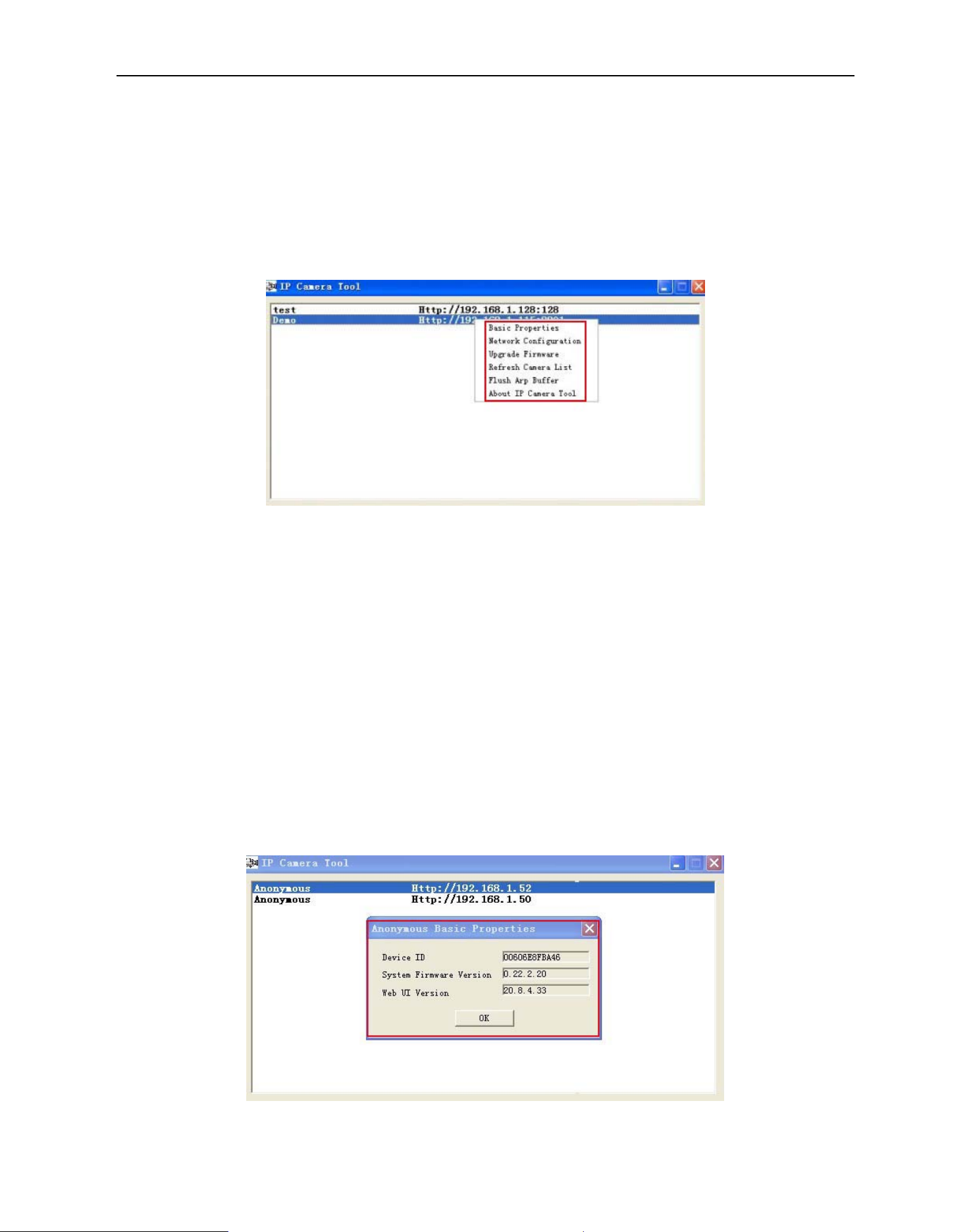
Choose the IP Camera list and Click right mouse, there are six options: (Figure 1.9)
Basic Properties, Network Configuration, Upgrade Firmware,
Refresh Camera List, Flush Arp Buffer, About IP Camera Tool
.
Figure1.9
2.1.1 .1 Basic Properties
There are some device information in the Basic Properties, such as Device ID, System Firmware Version,
Web UI Version.(Figure 2.0)
The Device ID just is the camera’s MAC ID, which should be the same as showed on the sticker at the bottom
of camera. Every camera has its unique MAC ID. So if there are many IP address showed in the list, check the
MAC ID, you can ensure which camera is it.
Sometimes, if there is no IP address showed on the IP Camera tool, maybe it’s blocked by firewall, then add
the MAC ID to the router, and give it a fixed IP or add the MAC ID as a trusted site. There are two MAC
Address, one is Device MAC ID, the other is WIFI MAC ID.
WIFI MAC ID, you can find it from the sticker at the bottom of the camera, if this sticker lost, you can login your
WIFI router, check the host status, which will show all the WIFI device connect to this router, you can also find
the IPCAM’s WIFI MAC ID there.
Figure2.0
8
MoreSecurity,MoreConvenience
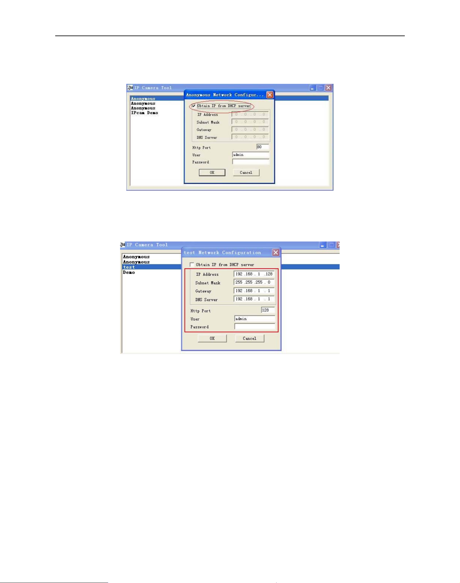
2.1.1.2 Network Configuration
In this page, you can configure the Network parameter.
Figure2.1
Obtain IP from DHCP server: If clicked, the device will obtain IP from DHCP server. In other words, the
camera will have a dynamic IP. (Make sure the Router which the camera connects has DHCP function and
DHCP is enabled). (Figure 2.1)
Figure 2.2
IP address: Fill in the IP address assigned and make sure it is in the same subnet as the Gateway, and the
subnet should be the same as your computer or router. (i.e. the first three sections are the same)
Subnet Mask: The default subnet mask of the equipment is: 255.255.255.0. You can find the subnet mask
from your PC or router.
Gateway: Make sure it is in the same subnet with PC’s IP address .Here gateway is the LAN IP of your router.
DNS Server: IP address of IPS network provider. You can also set it’s the same as the Gateway.
NOTE: You can find the Subnet Mask, Gateway, DNS Server from your router, or check the local connection
status of your computer, get all the parameters. Normally two DNS servers are optional.
Http Port: LAN port assigned for the equipment, default is 80. You could set another port number like 81, 801,
8001 etc.
User: Default administrator username is: admin (please make sure all are lowercase letter)
Password: Default password is bank, no password.
NOTE: When prompt “subnet doesn’t match, double chick to change!” appeared, please set the IP Address,
Subnet Mask, Gateway, DNS Server once again, or enable Obtain IP from DHCP server.
9
MoreSecurity,MoreConvenience
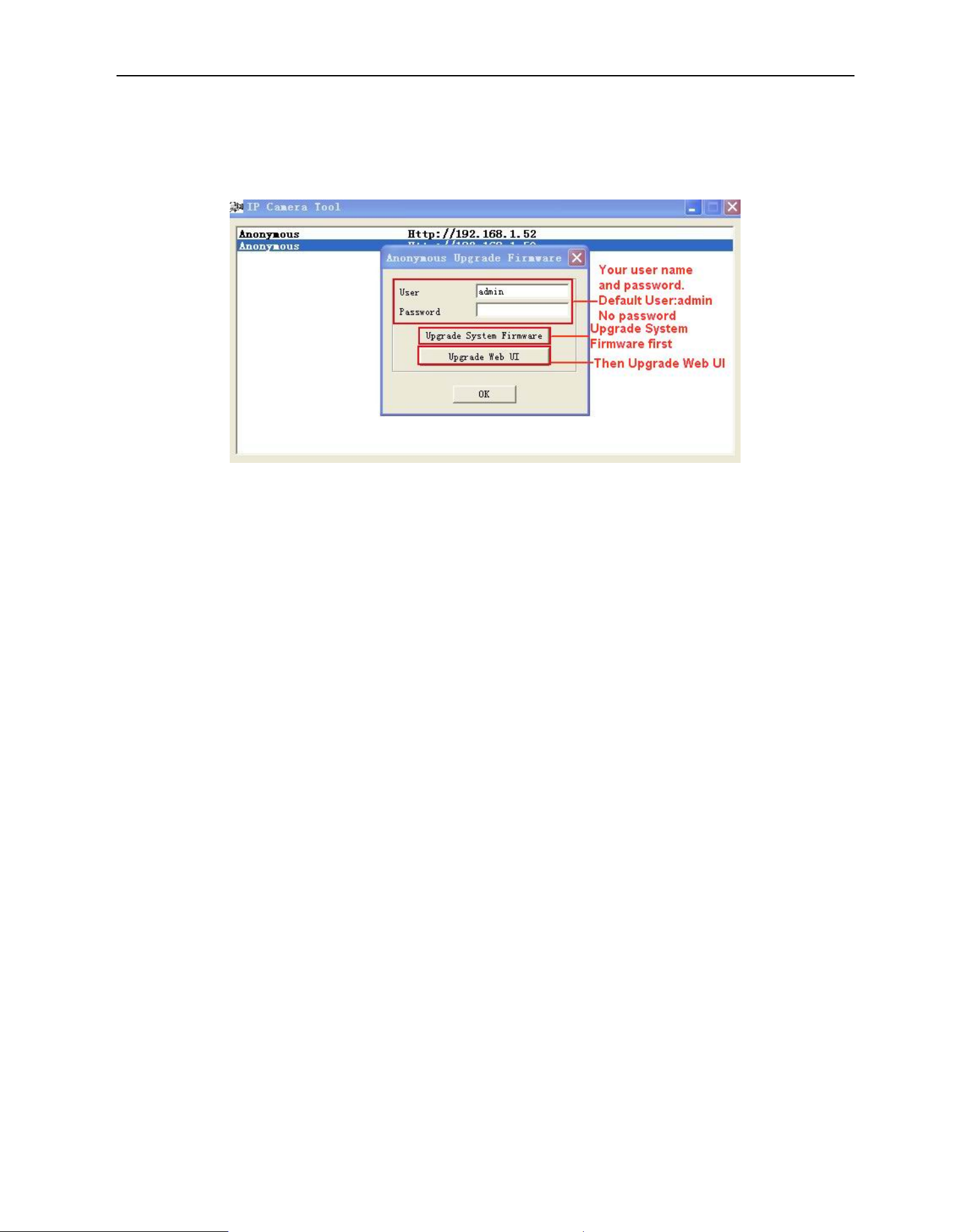
2.1.1.3 Upgrade Firmware
Enter the correct User and Password to upgrade system Firmware and Web UI. If you upgrade the camera,
Please upgrade system firmware first and then upgrade Web UI. Or it may damage the camera.(Figure
2.3)
Figure 2.3
Please download the firmware package under the correct type of your camera before upgrade.
Follow the upgrade document in the package carefully to upgrade. Please look readme firstly before you do
upgrade.
CAUTION: Please don’t upgrade the firmware freely. Sometimes, your camera may be damaged if wrong
operation during upgrade.
If your camera works well with the current firmware, we recommend you’d better not upgrade it.
NOTE: When doing upgrade, please must keep the power on, and the best use wired mode, connect the
network cable.
2.1.1.4 Refresh Camera List
Refresh camera list manually.
2.1.1.5 Flush Arp Buffer
When cable network and wireless network of the device are fixed IP address .There is a problem you may
encounter is can search the camera IP but can’t open the camera web page .you may try to use Flush Arp
Buffer.
2.1.1.6 About IP Camera Tool
Check the IP Camera Tool Version and IP Camera ActiveX Control Version here.
2.2 Camera Login
You can access the camera through IP Camera Tool or IE, Firefox, Safari, Google Chrome or other
standard browser directly.
1. Double click the IP address of the IP Camera listed (Figure 1.8). The default browser you use will run
automatically and come to the camera login interface. (Figure 2.6)
10
MoreSecurity,MoreConvenience
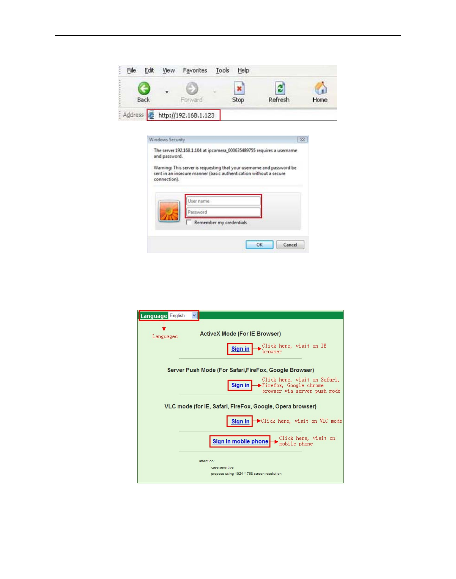
2. To access the camera by IE Browser directly, just type the camera’s IP address, for example, if the camera’s
IP address is 192.168.1.123:
Figure 2.4
Figure 2.5
The default user name is admin, no password
Input the correct user name and password, the Sign In interface will pop-up.
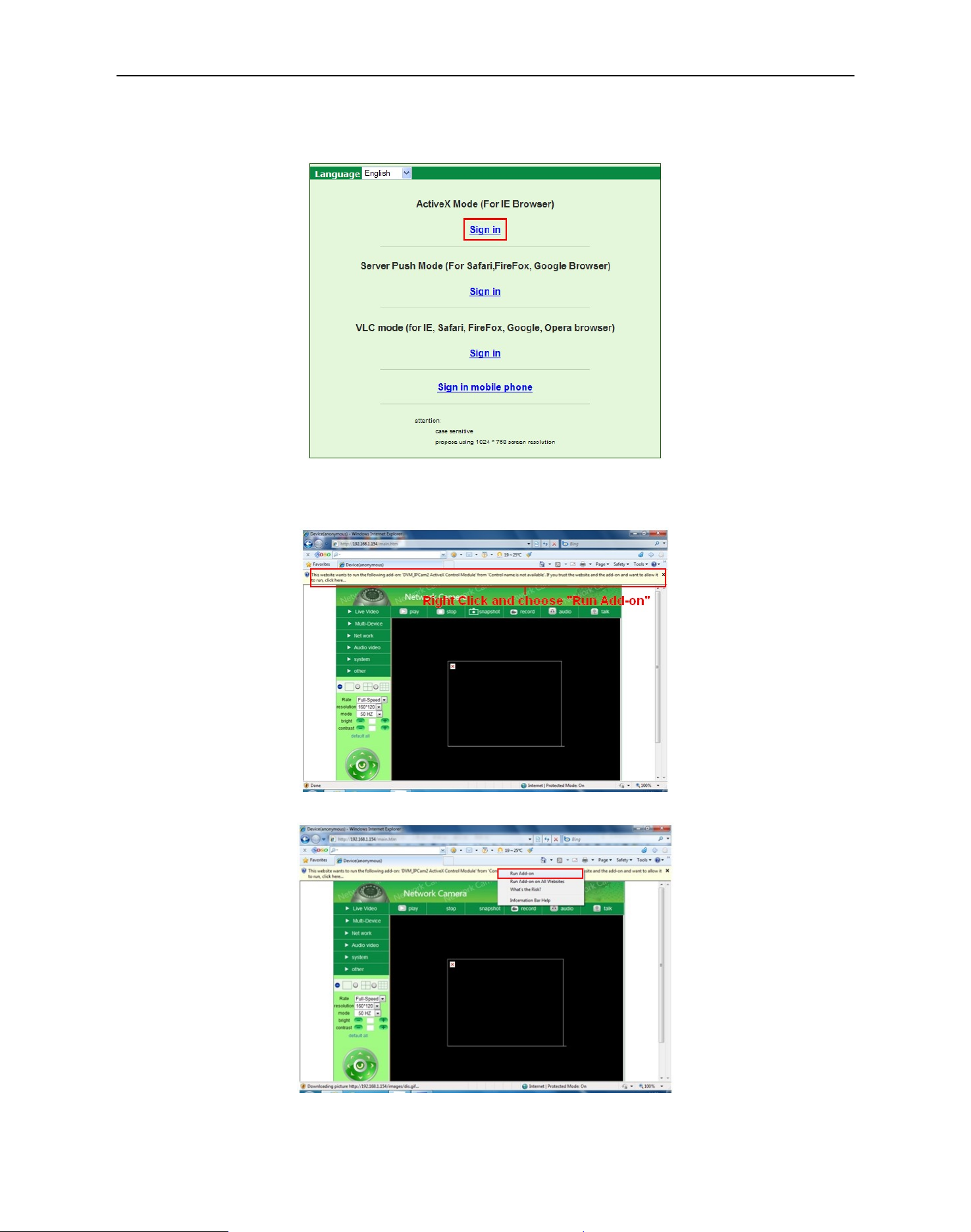
There are three models to login (figure 2.6).
Figure 2.6
(1) Active Mode (For IE Browser): available in IE6.0 or above explorer
(2) “Server Push Mode”: available in Firefox, Safari, and Google Chrome browser.
(3) “Sign in mobile phone”: available in Mobile phone
11
MoreSecurity,MoreConvenience
2.3 For IE Browser
Choose Active Mode (For IE Browser), and sign in.
Figure 2.7
The first time login the camera, maybe get ActiveX prompt as the picture above, please click the prompt and
choose Run Add-on, refresh and login the camera again, then will see live video, details as below
Figure2.8
:
Figure 2.9
12
MoreSecurity,MoreConvenience
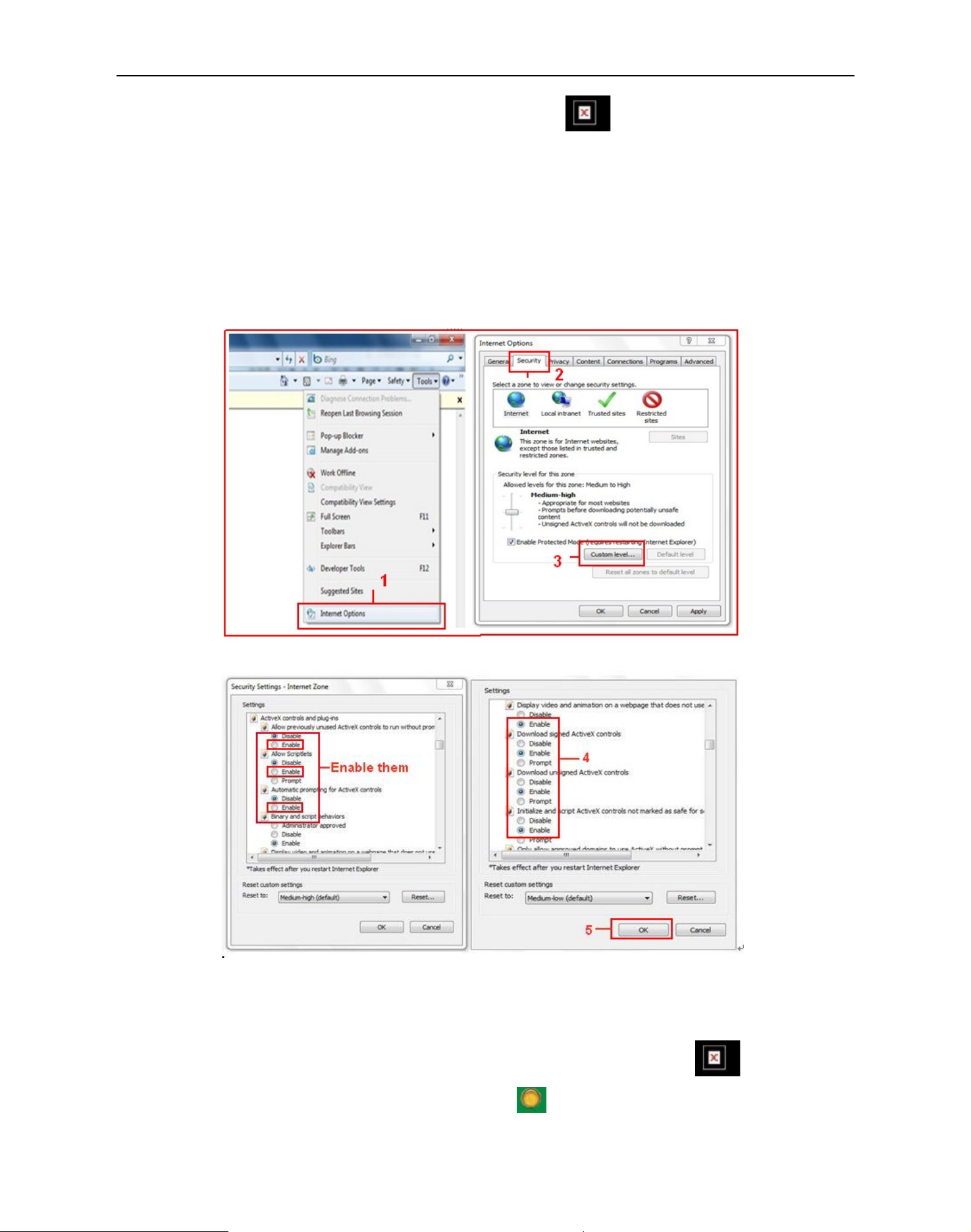
Note: If there is still no live video after run ActiveX, and a red cross showed in the center of the screen,
or even just a black screen, please try to enable the ActiveX options of IE security settings.
Please do the follow steps:
1. Close the firewall of your computer.
2. Change the ActiveX settings, “IE” browser > “Tool” > “Internet Options” > “Security”> “Custom Level” >
“ActiveX control and Plug-ins”, all the ActiveX options set to be “Enable”:
Especially:
Enable: Download unsigned ActiveX controls
Enable: Initialize and script ActiveX controls not marked as safe
Enable: Run ActiveX controls and plu-ins
Figure3.0
Figure 3.1
In addition: you can also click “Start” menu->“Internet Explorer”, choose “Internet attributes “ to enter, or via
“Control Panel” ->“Internet Explorer”, enter to Security setting.
If you allowed the ActiveX running, but still could not see live video, only a Red Cross
the video, and the device status light change to yellow color
13
, not green, please change another port
in the center of
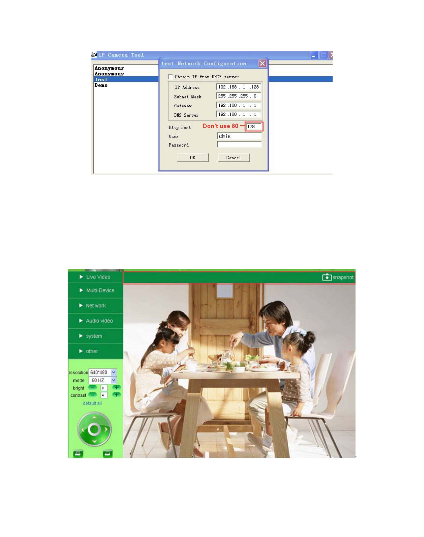
MoreSecurity,MoreConvenience
number to try. Don’t use port 80, use other port such as 128, 1008 etc.
Figure 3.2
NOTE: Make sure that the firewall or anti-virus software doesn’t block the software or ActiveX. If you couldn’t
see live video, please close your firewall or anti-virus software, and try again
.
2.4 For Safari, Firefox, Google Browser
Choose Server Push Mode (For Safari, Firefox, Google Browser), and sign in
Server Push Mode doesn’t support ActiveX, so some functions are not available, such as Play, Stop, Record,
Audio, Talk etc. if you want to use these functions, please use IE browser
.
Figure 3.3
14
MoreSecurity,MoreConvenience
2.5 For Mobile Phone
Choose Sign in mobile phone, and sign in.
Mobile phone doesn’t support ActiveX, only some basic functions can be available in this mode.
It supports Iphone, Smart phone, 3G phone etc. Normally, if the mobile phone supports network video, then it
can work with our IP Camera.
Figure 3.4
2.6 ActiveX Mode (For IE Browser)
Login the camera in ActiveX mode, the main User Interface as below:
NOTE: There are 3 levels of users, Visitor, Operator, Administrator, if you login with different users, the use
authority is different. (See 3.11 User Settings, Figure 8.5)
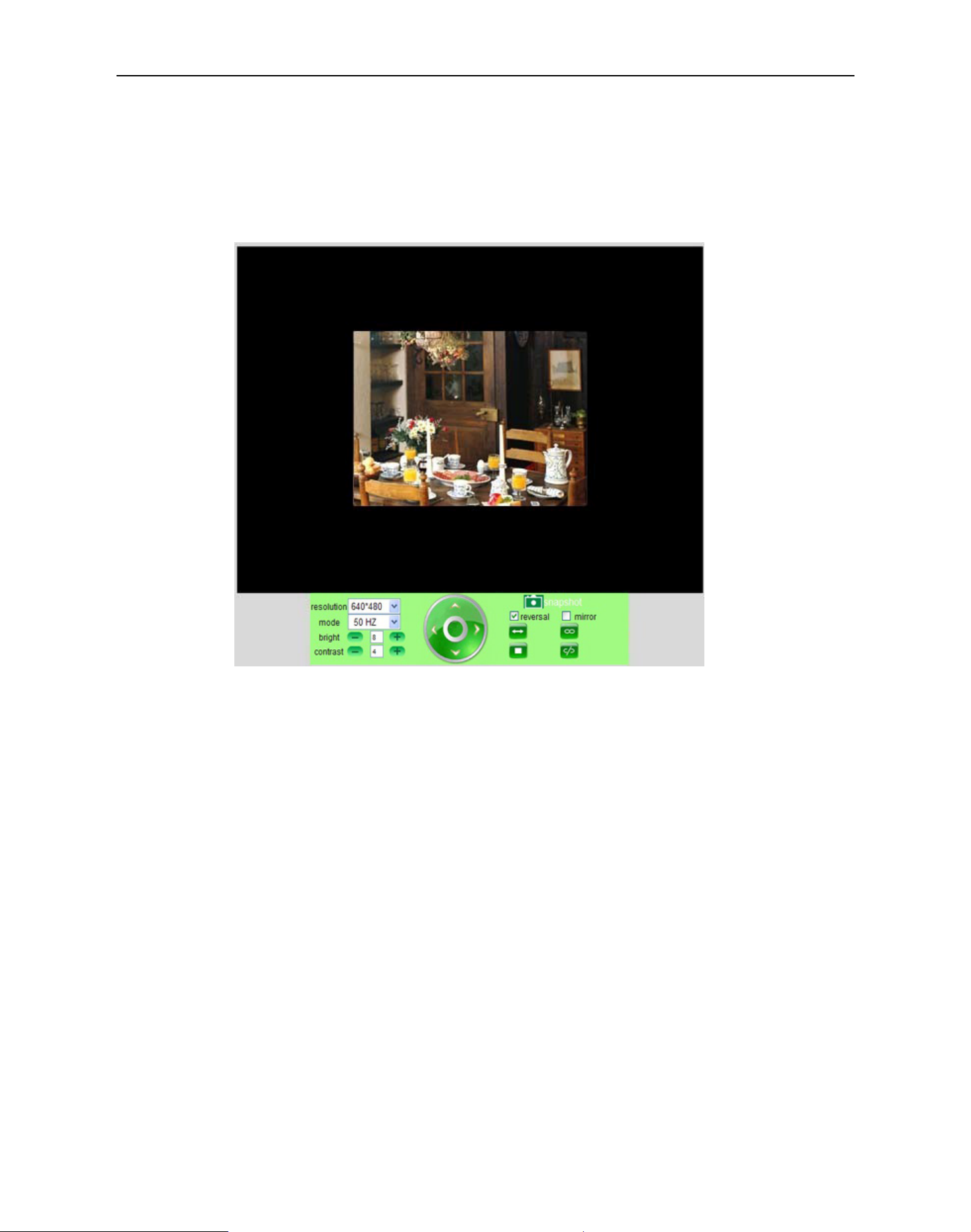
2.7 For Visitor
When login as Visitor, you can enter the IP Camera for visitor.
Visitor is the lowest level with only some operation available
15
MoreSecurity,MoreConvenience
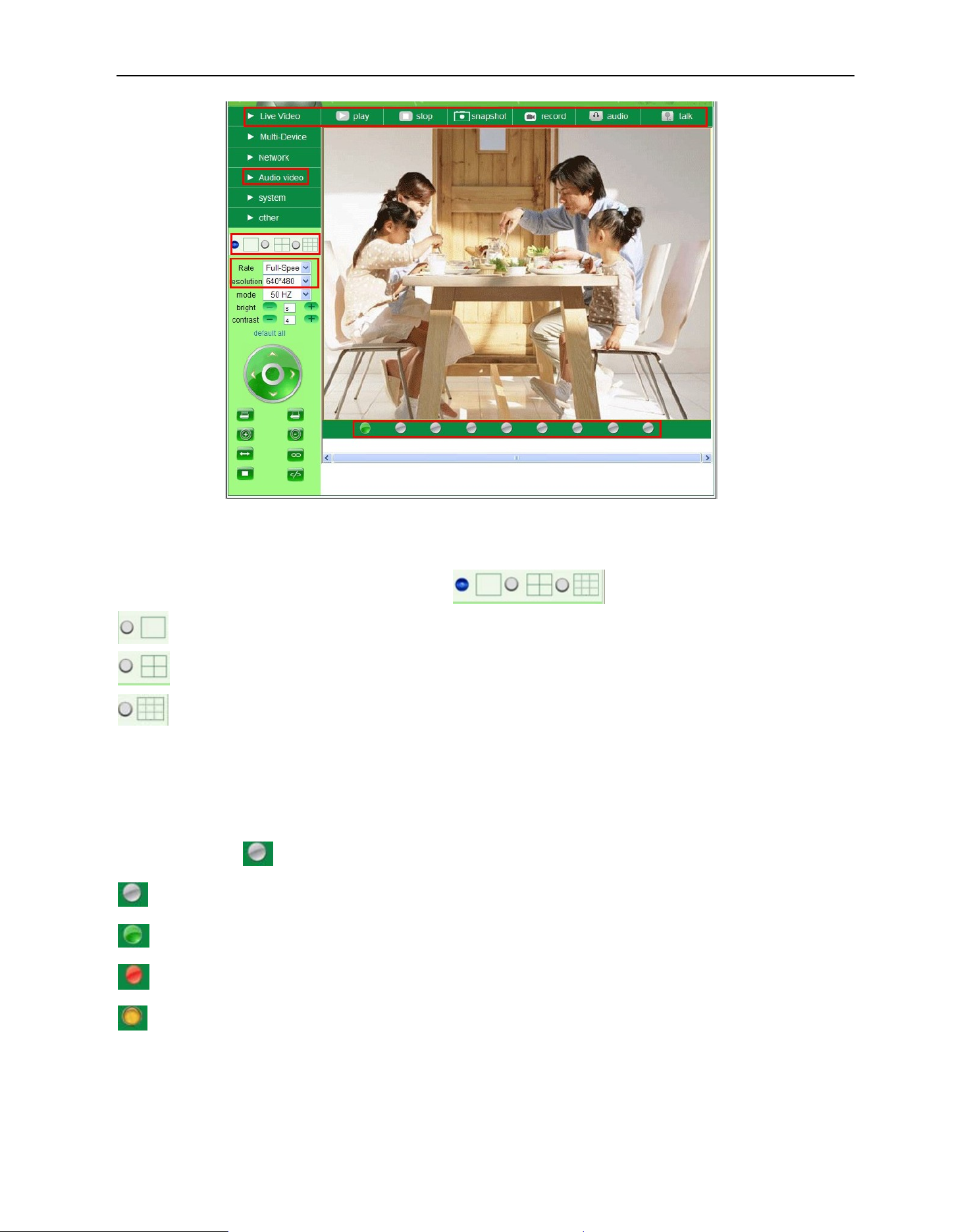
Figure 3.5
Channels:
Our IE software supports 9 channels totally. Click
: Click this one, you can view the main channel of the camera you login.
: Click this one; you can view 4 Channels of cameras which connected, from CH1 to CH4.
: Click this one; you can view 9 Channels of cameras which connected, from CH1 to CH9.
can get different windows.
NOTE: If you want to view 4/9 channels, you should set the Multi-Device firstly (See 3.1 Multi-Device
Settings)
Status of Channels:
There are 9 icons at the bottom of the UI which show the status of each channel of the camera.
: Grey color, means there is no device connected to the main device from this channel.
: Green color, means the device connected from this channel, and it works well.
: Red color, means the device of this channel is recording.
: Yellow color, means set this channel in multi-device already, but it fails to connect to the main device.
16
MoreSecurity,MoreConvenience
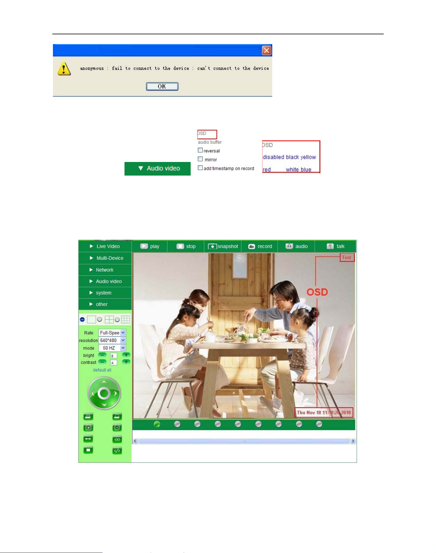
OSD Settings:
Î Î
Figure 3.6
OSD: Means “On-Screen Display”, click “Audio video” > “OSD”, set display date and time on the video.
Disabled: Click this one, means clear the OSD.
Color: Can set the OSD text color as black, yellow, red, white, blue etc.
Add time stamp on record: Click this, there will be time OSD on record video files.
Figure 3.7
17
 Loading...