

Page 1
Dual Fuel Range
Service Instructions
This book contains many important safety messages.
Always read and obey all safety messages.
F104650-01
www.aga-ranges.com
Page 2

Page 3

Contents
Servicing Notes 4
1. To Remove the Hand Rail 4
2. To Remove Control Panel 4
3. To Remove the Cooktop 4
4. To Remove a Side Panel 4
5. To Remove Oven Light Switch 5
6. To Remove Electronic Timer 5
7. To Remove a Thermostat 5
8. To Change Broiler Controller 5
9. To Change a Cooktop Tap 5
10. To Change a Cooktop burner orifice 5
11. To Change Cooktop Burner Electrode 5
12. To Remove or Change a Cooktop Burner. 6
13. To Remove Broiler Outer Door Panel 6
14. To Remove Main Oven Door 6
15. To Change Main Oven Door Outer Panel 7
16. To Change Main Oven Door Catch 7
17. To Change Oven Door Seal 7
18. To Adjust Oven Door Catch Keep 7
19. To Change Ignition Generator 8
20. To Remove Oven Inner Back. 8
22. To Replace an Oven Fan 8
23. To Remove an Oven fan Element 8
24. To Remove Broiler Element. 8
25 To Remove the LH Oven Bottom and Top Elements 9
26. To change Main oven light bulb. 9
27 To Remove Tall Oven Door 9
28. To Change Tall Oven Door Outer Panel 9
29. To Change Tall Oven Door Magnetic Latch 9
30. To Replace the Cooling fan 9
Schematic diagram of the Range 10
Technical Data 12
Page 4
SERVICING - WARNING
Disconnect from electricity and gas before servicing. Check appliance is safe when you have finished.
Pull the control panel forward and support so that
Servicing Notes
When servicing or replacing gas carrying
components disconnect from gas before
commencing operation and check appliance is
gas sound after completion. When checking for
gas leaks use a liquid leak detector at all joints
and connections to check for leaks in the system.
Use a product specifi cally manufactured for leak
detection. Leak testing of the appliance shall be
conducted in accordance to the manufacturer’s
instructions.
the wires are not strained.
Reassemble in reverse order. When replacing
leads refer to the wiring diagram. Check operation
of timer, ignition, and oven light switches.
3. To Remove the Cooktop
Disconnect from electricity supply.
Remove the pan supports, cooktop burner caps
and tops. If there are screws holding the cooktop
burners to the cooktop, remove them (not the
spark electrode fi xing screws).
CAUTION: DO NOT USE A FLAME TO
CHECK FOR GAS LEAKS.
Do not use re-conditioned or unauthorised gas
controls.
Disconnect from electricity supply before
commencing servicing, particularly before
removing any of the following: control panel,
side panels, cooktop tray, or any of the electrical
components or cover boxes. Before electrical
reconnection make sure the range is electrically
safe.
1. To Remove the Hand Rail
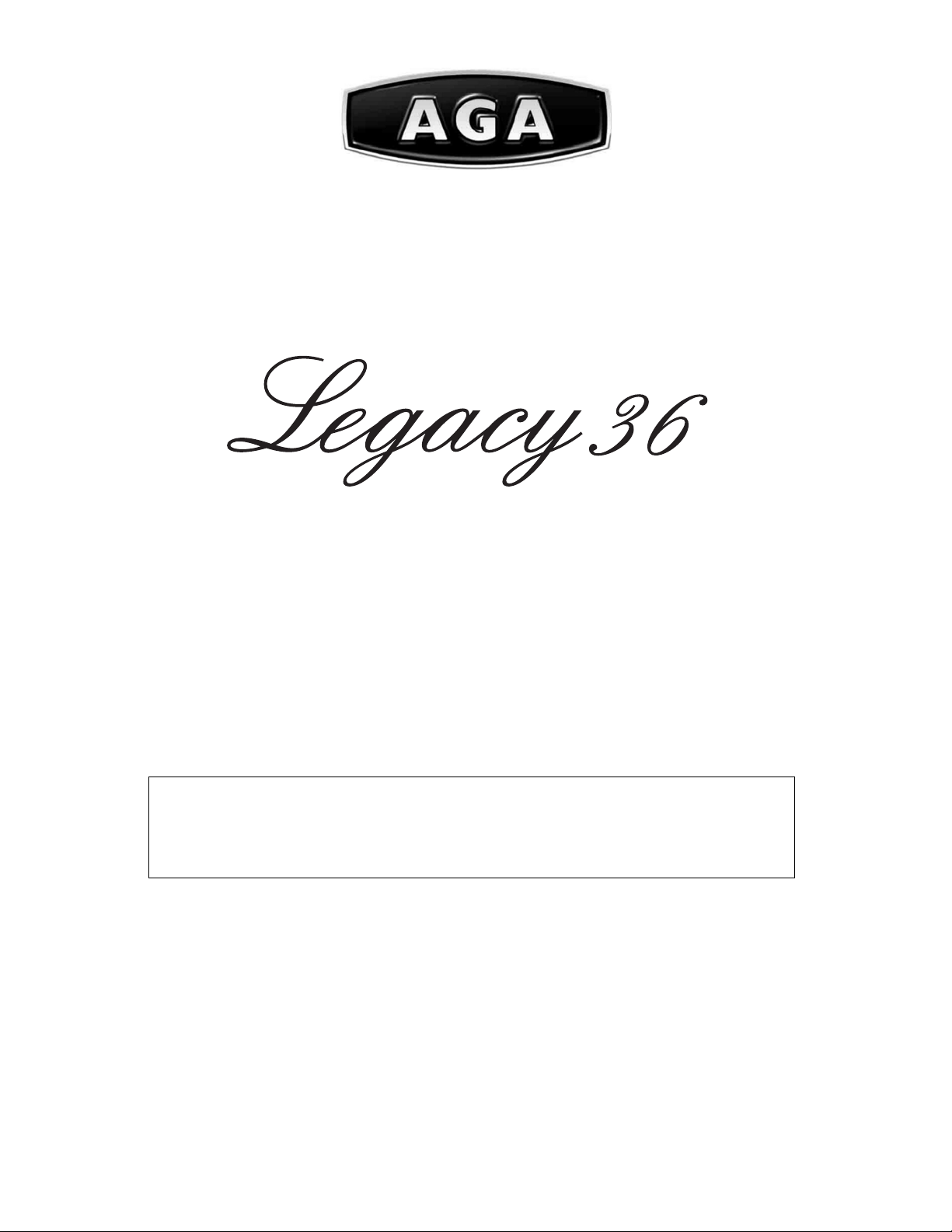
Remove the handrail plastic blanking plugs and
remove the 2 end bracket fi xing screws.
2. To Remove Control Panel
Disconnect from electricity supply.
Pull off all the control knobs. Remove the handrail
(see 2) Remove the 2 cross headed screws that
were hidden by the handrail end brackets.
Open the broiler door and R H oven door and
remove the 2 screws underneath the control
panel.
A Cooktop front fixing screws
B Cooktop rear fixing screws
Remove the 4 rear cooktop fi xing screws (B) and
the 4 front cooktop fi xing screws (A).
Remove the screws holding the fl ue grille stays.
Lift the cooktop clear of the appliance. Replace in
reverse order.
Reassemble in reverse order ensuring that the
leads are reconnected.
Check for correct burner operation.
4. To Remove a Side Panel
Disconnect from electricity supply.
Remove control panel (see 2). Pull the cooker
forward. Remove the 4 retaining screws for each
panel (2 at the front and 2 at the rear). The lower
front retaining screws (one each side) are situated
beneath the lower edge at the front corners of the
side panels
Reassemble in reverse order.
4
Page 5
SERVICING - WARNING
Disconnect from electricity and gas before servicing. Check appliance is safe when you have finished.
5. To Remove Oven Light Switch
Remove control panel (see 2).
NB The old switch may be destroyed during
removal.
Remove switch button and old switch from its
bezel by gripping the switch body behind the
control panel and twisting sharply.
The switch bezel can then be removed by folding
back its locking wings and pushing forward. Fit
the new bezel to the control panel by fi rst lining
up the raised key on its body with the cutout in
the control panel and pushing it in from the front.
Assemble the new switch to the bezel by lining up
the key sections and pushing home. Fit the new
button by pushing in from the front.
Replace control panel in reverse order and test for
correct operation.
6. To Remove Electronic Timer
Disconnect from electricity supply.
Pull off the timer control buttons and remove
the control panel (See 2). Remove the timer/
mounting bracket assembly from the control panel
by removing the two fi xing screws. Remove the
timer from its mounting bracket by depressing the
plastic lugs on the timer case, at the same time
pulling the unit forward.
Reassemble in reverse order. When replacing
leads refer to the wiring diagram. Check operation
of timer.
5
Page 6

SERVICING - WARNING
Disconnect from electricity and gas before servicing. Check appliance is safe when you have finished.
7. To Remove a Thermostat
Remove control panel (see 2) and cooktop (see
3). Open the appropriate oven door and remove
the oven shelves.
RH oven
Remove oven roof. Remove the two fi xings that
secure the thermostat phial cover. Unclip the
thermostat phial from the clips in the oven back
panel & remove from the top rear of the oven.
LH oven
Remove the two screws holding the thermostat
phial to the oven fan cover at the rear of the
oven. Pull the unit forward to access the rear
of the cooker. Remove both rear cover boxes
by removing the fi xing screws and lifting clear.
Feed the thermostat capillary clear of the oven.
Disconnect the wires from the thermostat and
undo the two fi xings that secure the control to
the mounting plate. Fit the replacement and reassemble in reverse order. Ensure that the phial
is clipped to the oven rear, positioned centrally
between the clips. Check that the thermostat
functions correctly.
8. To Change Broiler Controller
Remove the control panel (see 2) and cooktop
(see 3). Disconnect wiring from controller. Remove
2 screws holding switch/controller to mounting
panel. Fit new controller and reassemble in
reverse order. Check for correct operation.
BEFORE SERVICING ANY GAS CARRYING
COMPONENTS TURN OFF GAS SUPPLY.
10. To Change a Cooktop burner orifi ce
Standard burner Wok burner
A orifice, B internal orifice, C external orifice
Remove burner cap and head. Remove old orifi ce.
Fit new orifi ce. Note the Wok burner has 2 orifi ces.
Reassemble in reverse order. Check appliance is
gas sound.
11. To Change Cooktop Burner
Electrode
Lift off hoplate pan supports, remove burner
cap. Remove the screw holding the electrode.
Pull electrode vertically up suffi ciently to grip
the lead between thumb and forefi nger. Pull off
the electrode, but keep hold of the lead. Fit new
electrode to the lead. Fix electrode in burner with
screw. Replace burner cap. Check the burner
ignition. Replace pan supports.
9. To Change a Cooktop Tap
Remove the cooktop top, see 3. Undo the nut
at rear of the valve and remove the screw(s)
securing valve to gas rail. Remove old valve,
discard old gasket/seal. Fit new gasket/seal to
new valve.
Reassemble in reverse order. Check valve is
adjusted for correct gas. Check cooker is gas
sound.
6
Page 7

SERVICING - WARNING
Disconnect from electricity and gas before servicing. Check appliance is safe when you have finished.
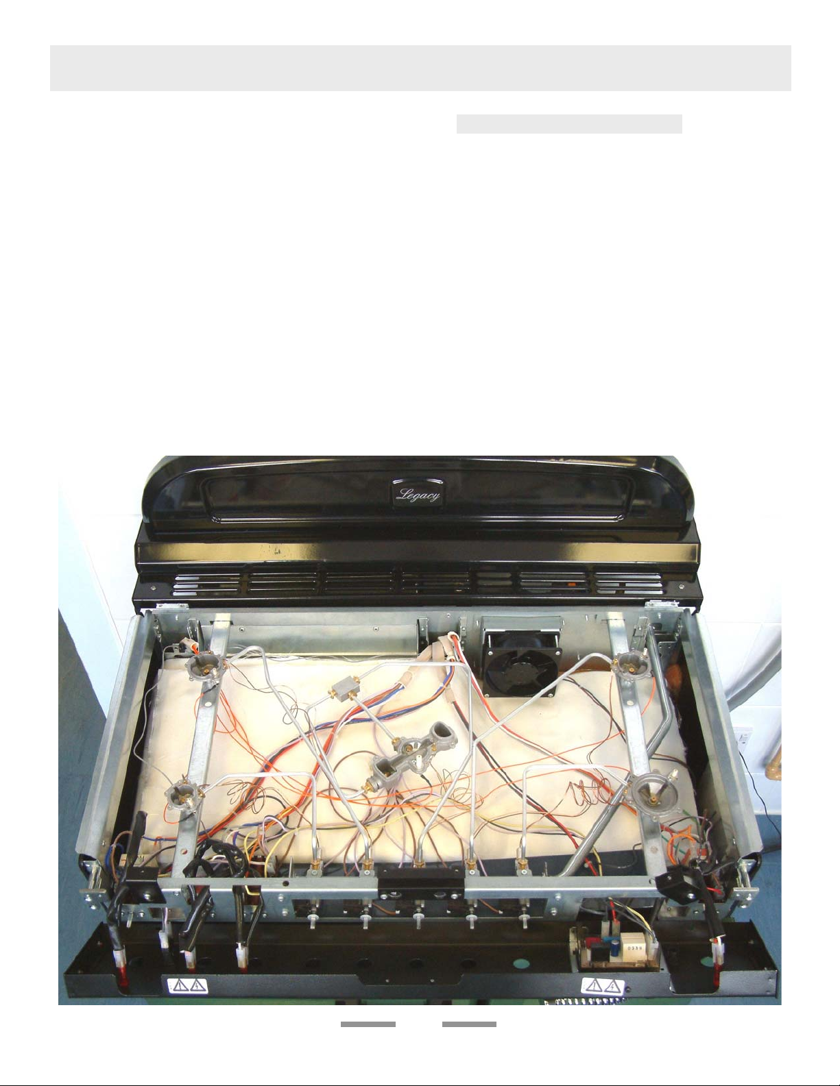
12. To Remove or Change a Cooktop
Burner.
Remove the cooktop tray (see 3). Remove the
control panel (see 2).
Outer Cooktop burners
The burners are mounted in 2’s on cross supports.
Disconnect the burner feed pipes at the burners.
Remove the screw at the front holding the
cross support. Slide the support to the right to
release in from the rear location. Lift the cross
support and burners clear. The burners are fi xed
to the cross supports with screws underneath.
Remove the appropriate burner and fi t the new
one. Reassemble in reverse order. Check burner
operation is satisfactory.
Wok burner
Disconnect the burner feed pipes at the burner.
Fit the new one and reassemble in reverse order.
Check burner operation is satisfactory.
13. To Remove Broiler Outer Door Panel
Open left hand oven door and remove 2 screws
from bottom edge of broiler door. Open broiler
door, support broiler door outer panel and remove
two screws from top inner face of broiler door.
There is a pad of fi bre insulation inside the door.
Reassemble in reverse order making sure that the
pad of insulation is in place.
14. To Remove Main Oven Door
Open oven door and remove Handyrack (where
fi tted) by springing one side out of the bracket on
the door and sliding the other side free. Support
the door and remove the two screws securing
the upper hinge and packing to the cooker front.
Remove the door from the lower hinge by lifting
slightly and moving outwards.
Reassemble in reverse order.
7
Page 8

SERVICING - WARNING
Disconnect from electricity and gas before servicing. Check appliance is safe when you have finished.
15. To Change Main Oven Door Outer
Panel
Remove the two plastic blanking plugs from the
door handles. Remove the 4mm Hex headed
screws holding the handle to the door with the
hexagon key tool. Remove two screws from top
edge and two from bottom edge of the door.
Remove outer door panel. Fit door handle to new
panel. Fit the plastic blanking plugs to the fi xing
holes.
The handles should be above the fi xings.
Fit panel to door. If replacing the outer panel on
the right hand door (with the Thermodial) take
care to make sure the sensor of the Thermodial is
sealed to the door by the rubber grommet.
16. To Change Main Oven Door Catch
Remove outer door panel (see 15). Remove
screws ‘B’ holding catch assembly to inner door
panel. Fit new catch and reassemble in reverse
order.
Check correct door operation.
17. To Change Oven Door Seal
Open oven door. The seal is held in place by small
hooks on the rear face. At the corner pull seal
diagonally away from the door centre until that
hook is released. Proceed to the next hook and
release it in a similar way, and so on.
Reassemble in reverse order.
Fig. 4
When fi tting new seal, position the seal join at the
bottom. Hook the new seal in one of the corner
holes of the door, and proceed round the door
snapping in each hook in turn.
18. To Adjust Oven Door Catch Keep
Open oven door, slacken off locknut at base
of keep, and screw in or out as required until
required fi t is obtained. Retighten locking nut.
8
Page 9

SERVICING - WARNING
Disconnect from electricity and gas before servicing. Check appliance is safe when you have finished.
19. To Change Ignition Generator
Disconnect from electricity supply.
Pull cooker forward to gain access to the cover
box at the rear of the left hand cooker. Remove
the screws securing the cover and lift clear.
Pull off all the leads to the generator noting
their positions. Slacken the two screws holding
generator to cooker and remove generator.
Fit new generator to cooker and replace leads.
Reassemble in reverse order. Refer to wiring
diagram. Check ignition performance.
20. To Remove Oven Inner Back.
Open the oven door. Remove oven furniture. For
the LH oven unscrew the 2 thermostat phial fi xing
screws.
22. To Replace an Oven Fan
Disconnect from electricity supply.
Pull the unit forward to access the cover boxes at
the rear of the appliance.
Remove the fi xings that secure the cover and
lift it clear. Remove the fan wiring, noting the
connection positions. Remove the inner back as
detailed in Section 20. Hold the fan blades and
undo the centre nut (LH thread), brass washers
and fan blade. Undo the fi xings that retain the
fan and remove it from the cavity rear. Fit the
replacement and re-assemble parts in reverse
order. Check that the oven operates satisfactorily.
23. To Remove an Oven fan Element
Disconnect from electricity supply.
Remove the inner back as detailed in Section 20.
Remove the fi xings that secure the inner back to
the oven rear.
Lift the removable panel away. Re-assemble in
reverse order. Ensure that the retaining fi xings
are fully tightened. For the LH oven unscrew the
2 thermostat phial fi xing screws. Remove the
screws that secure the inner back to the oven rear.
Lift the removable panel away. Re-assemble in
reverse order. Ensure that the retaining fi xings are
fully tightened.
Remove the fi xings that secure the element
within the oven and lift the element away
carefully. Disconnect the leads and connect to
the replacement element and re-assemble parts
in reverse order. Check that the oven operates
correctly.
24. To Remove Broiler Element.
Disconnect from electricity supply.
Remove broiler pan from broiler chamber. From
inside broiler compartment remove enamelled
front shield from broiler roof, 2 screws and
washers. Remove 2 screws and washers securing
the broiler element front support. Remove 1 screw
from each of the broiler elements and withdraw
broiler elements from broiler chamber. Disconnect
the leads and connect to the replacement
elements and re-assemble parts in reverse order.
Check operation of broiler.
9
Page 10

SERVICING - WARNING
Disconnect from electricity and gas before servicing. Check appliance is safe when you have finished.
25 To Remove the LH Oven Bottom and
Top Elements
Disconnect from the electricity supply.
Bottom Element
Pull the cooker forward to access the cover boxes
at the rear of the unit. Remove the fi xings that
secure the cover and lift it clear.
Remove the 2 screws ‘A’ and allow the plate to
drop down.
26. To change Main oven light bulb.
Disconnect from the electricity supply.
Remove the oven furniture. Unscrew the bulb.
Fit an Edison screw fi tting 15w 125-130v lamp,
FOR OVENS. It must be a special bulb, heat
resistant to 300 °C.
27 To Remove Tall Oven Door
Open oven door, support the door and remove the
two screws securing the upper hinge and packing
to the cooker front. Remove the door from the
lower hinge by lifting slightly and moving outwards.
Reassemble in reverse order.
28. To Change Tall Oven Door Outer
Panel
Remove oven door see 16. Lay door face down
on a suitable surface and remove 2 screws from
bottom edge of door and 2 screws from inside
face of door.
Remove outer door panel. Remove door handle
by unscrewing 2 screws. Remove 2 cross-headed
screws holding door handle fi xing bracket to door
panel. Fit door handle bracket and door handle to
new panel.
Fit panel to door. Reassemble in reverse order.
Remove the 2 screws B, holding the element to
the bottom sheet.
Disconnect the leads, noting their positions.
Withdraw bottom element. Fit the new element
and re-assemble parts in reverse order.
Top Element
Open the LH oven door and undo the fi xings that
secure the heat shield. Remove the top element
bracket fi xings and withdraw element. Replace the
element and re-assemble parts in reverse order.
Check that the oven operates satisfactorily.
29. To Change Tall Oven Door Magnetic
Latch
Remove the control panel (see 4).
Remove the plinth (3 screws) and the central
vertical cover (5 screws). Prize the retaining clip
off the magnet unit. Fit new unit and retaining clip.
Reassemble in reverse order.
Check correct door operation.
10
Page 11

SERVICING - WARNING
Disconnect from electricity and gas before servicing. Check appliance is safe when you have finished.
30. To Replace the Cooling fan
Disconnect from electricity supply.
Remove the cooktop see 3.
Disconnect the leads from the fan noting the
orientation. Remove the fan from the mounting
bracket. Fit the new fan and reassemble in reverse
order.
11
Page 12

SERVICING - WARNING
Disconnect from electricity and gas before servicing. Check appliance is safe when you have finished.
Code Description
BRE Broiler elements
BSB Broiler switch block
BTC Broiler controller
CFM Cooling fan motor
IGS Ignition switches
ISG Ignition spark generator
LBE Left hand bottom element
LFE Left hand fan element
LTI Left hand top inner element
LTO Left hand top outer element
LOS Left hand oven switch block
Code Color
BK Black
NLI Neon indicator light
OFM Oven fan motor
OLS Oven light switch
BL Blue
BR Brown
GY Grey
OTL Left hand oven thermostat
OTR Right hand oven thermostat
OVL Oven light bulb
O Orange
R Red
V Violet
ROE Right hand oven element
RSB Right hand oven switch block
W White
Y Yellow
TCK Timer clock
TCO Thermal cut out
Schematic diagram of the Range
Caution: Label all wires prior to disconnection when servicing controls. Wiring errors can cause improper and dangerous
operation. Verify proper operation after servicing.
12
Page 13

SERVICING - WARNING
Disconnect from electricity and gas before servicing. Check appliance is safe when you have finished.
Schematic diagram of the Range
Caution: Label all wires prior to disconnection when servicing controls. Wiring errors can cause improper and dangerous
operation. Verify proper operation after servicing.
13
Page 14

SERVICING - WARNING
Disconnect from electricity and gas before servicing. Check appliance is safe when you have finished.
Technical Data
This range is supplied set for Natural gas.
A conversion kit from NG to LP gas is included.
INSTALLER: Please leave these instructions with the User.
DATA BADGE LOCATION: Under the Main oven. Remove the plinth by pulling forward (it is held in
place by magnetic catches) and pull forward on the sheet metal tag under the center of the oven to swing
out the badge plate.
Country of Destination: USA/Canada
Gas Electric
Natural Gas 4.0” W.C (10 mbar)
Propane
(See appliance data badge for test pressures)
10.0” W.C (25 mbar)
Dimensions
Overall height (splash not fi tted) minimum 35 3/8” (89.8 cm) maximum 36 7/16” (92.5 cm)
Overall width
Overall depth with spacer 28 3/4” (73cm)
Space for fi xing See ‘Positioning the Range’
Minimum space above cooktop 30” (76cm)
240V 60Hz
35 1/2” (90cm) See ‘Positioning the Range’
Connections
Gas : Electric:
1
”
/
NPT at rear right-hand side
2
240 V 60 Hz
14
Page 15

SERVICING - WARNING
Disconnect from electricity and gas before servicing. Check appliance is safe when you have finished.
Orifices
A Wok burner
B Large Burner
C Medium Burners
D Small Burner
A valve bypass screw
Ratings
Natural Gas Propane Gas
Cooktop
Wok burner 15,000Btu/hr
Large Burner 12,000Btu/hr 170 70 12,000Btu/hr 106 38
Medium Burners 9,200Btu/hr 150 53 8,000Btu/hr 84 31
Small Burner 5,000Btu/hr 107 43 4,200Btu/hr 61 22
Gas burner inputs based on Gross Calorifi c Value
Ovens
Fan element 2.5kW 2.5kW
Top element 1.2kW
Browning Element 1.15kW
Bottom element 1.0kW
Left hand Multifunction Oven Right hand Fan Oven
Broiler
Maximum total electrical load at 240V 7.4kW (approximate total including oven lights, oven fan etc.)
Orifi ce Screw Orifi ce Screw
internal 110
82 15,000Btu/hr
external 166 external 93
2.3kW
internal 71
49
15
Page 16

Aga Ranges
110 Woodcrest Road
Cherry Hill, NJ 08003 USA
1.866.4AGA.4USA
www.aga-ranges.com
Email support@aga-ranges.com
 Loading...