

AGA marvel MP24BCF4, MP24BCG4, MP24RAS4, MP24RAP4, MP24BRG4 Installation, Operinstallation, Operation And Maintenance Instructions
...Page 1

EN Installation, Operation and Maintenance Instructions
FR Instructions d’installation, d’utilisation et d’entretien
ES Instrucciones de instalación, operación y mantenimiento
Built in Refrigerators
Réfrigérateurs intégrées
Refrigeradores
empotradas
MP15BCG4**
MP15BCF4**
MP24BCG4**
MP24BCF4**
MP24BRG4**
MP24BRF4**
MP24RAS4**
MP24RAP4**
MP24WBG4**
MP24WBF4**
Page 2
INSTALLING YOUR APPLIANCE
Select Location
The proper location will ensure peak performance of your
appliance. We recommend a location where the unit will
be out of direct sunlight and away from heat sources. To
ensure your product performs to specications, the recommended installation location temperature range is from 55
to 100°F (13 to 38°C).
Cabinet Clearance
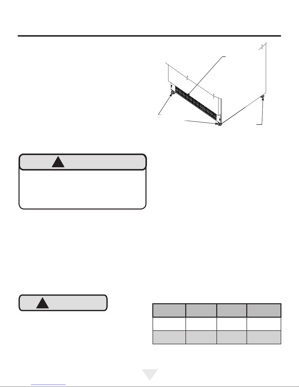
Ventilation is required from the bottom front of the appliance. Keep this area open and clear of any obstructions.
Adjacent cabinets and counter top can be installed around
the appliance as long as the front grille remains unobstructed. All Marvel Professional models with articulated hinges
are intended for built-in applications only.
!
WARNING
An optional stacking kit, for 24" wide models, is required to stack products. Failure to use a stacking kit
could result in personal injury. Contact your dealer or
Aga Marvel customer service at 800-223-3900 to order.
For safety concerns 15" wide models should not be
stacked.
Front Grille,
keep this area
open.
Front Leveling
Legs
Figure 2
Rear
Leveling
Legs
Leveling Legs
Adjustable legs at the front and rear corners of the appli-
ance should be set so the unit is rmly positioned on the
oor and level from side to side and front to back. The over-
all height of your Marvel appliance may be adjusted higher
(by turning the leveling leg out, CCW) and lower (by turning
the leveling leg in, CW) dimensions as shown in Table "A".
To adjust the leveling legs, place the appliance on a solid
surface and protect the oor beneath the legs to avoid
scratching the oor. With the assistance of another person,
lean the appliance back to access the front leveling legs.
Raise or lower the legs to the required dimension by turning
the legs. Repeat this process for the rear by tilting the appliance forward using caution. On a level surface check the
appliance for levelness and adjust accordingly.
!
CAUTION
Front Grille
Do not obstruct the front grille. The openings within the
front grille allow air to ow through the condenser heat exchanger. Restrictions to this air ow will result in increased
energy usage and loss of cooling capacity. For this reason
it is important this area to not be obstructed and the grille
openings kept clean. AGA MARVEL does not recommend
the use of a custom made grille as air ow may be restricted. (See Figure 2).
The front grille screws may be loosened and the grille adjusted to the desired height. When adjustment is complete
tighten the two front grille screws. (See Figure 5).
Model Door Style
MP(15)(24)* (S) or (G)
MP(15)(24)* (F)
Minimum
Height
34"
(86.4 cm)
34"
(86.4 cm)
Table A
Maximum
Height
35"
(88.9 cm)
35"
(88.9 cm)
4
Page 3
INSTALLING YOUR APPLIANCE
!
WARNING
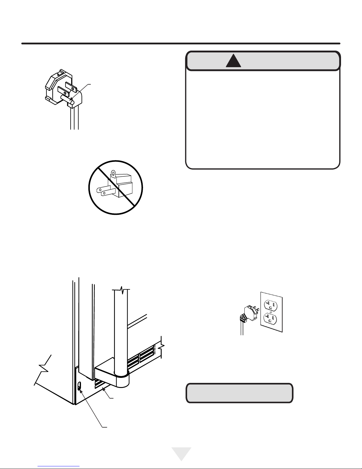
Figure 3
Do not remove
ground prong
Figure 4
Electrical Shock Hazard
• Do not use an extension cord with this appliance.
They can be hazardous and can degrade product
performance.
• This appliance should not, under any circumstances, be installed to an un-grounded electrical supply.
• Do not remove the grounding prong from the power
cord. (See Figure 3).
• Do not use an adapter. (See Figure 4).
• Do not splash or spray water from a hose on the
appliance. Doing so may cause an electrical shock,
which may result in severe injury or death.
Electrical Connection
A grounded 115 volt, 15 amp dedicated circuit is required.
This product is factory equipped with a power supply
cord that has a three-pronged, grounded plug. It must be
plugged into a mating grounding type receptacle in accordance with the National Electrical Code and applicable local codes and ordinances (see Figure 6). If the circuit does
not have a grounding type receptacle, it is the responsibility
and obligation of the customer to provide the proper power
supply. The third ground prong should not, under any circumstances, be cut or removed.
Front grille
Front grille screw
Figure 5
Figure 6
NOTE
Ground Fault Circuit Interrupters (GFCI) are prone to nuisance tripping which will cause the appliance to shut down.
GFCI’s are generally not used on circuits with power equipment that must run unattended for long periods of time, unless required to meet local building codes and ordinances.
5
Page 4
OVERLAY DOOR PANEL INSTALLATION
!
WARNING
Use extreme caution with the articulated hinges. The
hinge is self closing and many pinch points exist prior
to built-in installation. Do not remove the cabinet "Z"
bracket from the top of the cabinet.
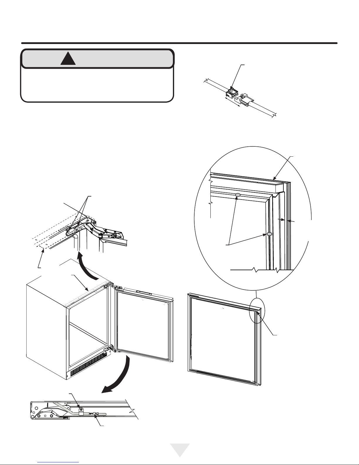
Press and hold this down
this tab on the wire connector and pull the connector
apart.
Step 2: Remove the door gasket
With the door laying on a at surface and starting at a
corner of the door remove the magnetic door gasket from
the interior side of the door, see Figure 13. Set the gasket
aside on a at surface.
There are 10 holes in the gasket retainer extrusions, (3 on
each side and 2 at the top and bottom which are used to
fasten the panel to the front of the door. The screws are
provided in the literature pack along with the door lock,
which is provided on certain models.
Loosen (do not remove ) these
2 phillips head screws on the
top and bottom hinges
Figure 11a
Cabinet
"Z" Bracket
Figure 12
Holes in
gasket
retainer.
Figure 13a
Overlay panel
ush with top
and side of
door.
Overlay panel to
be centered on
width of door.
Figure 11
"P" clamp
and screw
Figure 11b
Bottom of
door
Wire connector
see Figure 12
Magnetic Gasket
remove starting at a
corner, grasp and pull
away from the door.
Figure 13
Step 3: Cut and drill the overlay panel
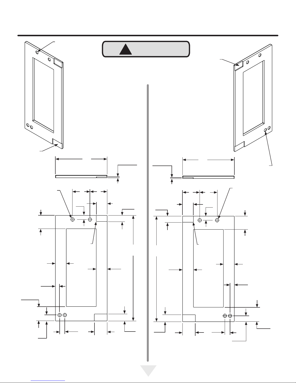
Depending on your model cut the overlay door panel to the
dimensions shown in Figures 14 to 21. The window cut out
is for glass door models only. If your appliance has a lock
also drill the lock hole in the panel, see Figure 22.
13
Page 5
Clearance for
screw head,
4 places
OVERLAY DOOR PANEL INSTALLATION
!
CAUTION
Weight of overlay door panel must not
exceed 15 pounds (6.8 kg) for a solid
door model or 10 pounds (4.5 kg) for a
glass door model.
Clearance
for hinge
2 places
Top of door
Clearance
for hinge
2 places
1" (25.4 mm) diameter
counter bore 1⁄4" (6.4mm)
deep 4 places.
327⁄32"
(9.7 cm)
31⁄8"
(7.9 cm)
Minimum
15⁄32"
(2.9 cm)
41⁄8"
(10.5 cm)
Minimum
Hinge side of door
Figure 14
Left Hand Hinged Door
15" (38.1 cm) wide appliance
143⁄4"
(37.5 cm)
5"
(12.7 cm)
13⁄16"
(3 cm)
1
⁄4" (6 mm)
radius is
permissible
This side
facing interior
47⁄8"
(12.4 cm)
1
31⁄8"
(7.9 cm)
31⁄8"
(7.9 cm)
Minimum
⁄4" (6 mm)
Deep
13⁄4"
(4.4 cm)
3011⁄32"
(77.1 cm)
Figure 16
Right Hand Hinged Door
15" (38.1 cm) wide appliance
1
⁄4" (6 mm)
13⁄4"
(4.4 cm)
3011⁄32"
(77.1 cm)
Deep
31⁄8"
(7.9 cm)
31⁄8"
(7.9 cm)
Minimum
(37.5 cm)
47⁄8"
(12.4 cm)
This side
facing interior
143⁄4"
5"
(12.7 cm)
13⁄16"
(3 cm)
1
⁄4" (6 mm)
radius is
permissible
Hinge side of door
Clearance for
screw head,
4 places
1" (25.4 mm) diameter
counter bore 1⁄4" (6 mm)
deep 6 places.
327⁄32"
(9.7 cm)
31⁄8"
(7.9 cm)
Minimum
15⁄32"
(2.9 cm)
111⁄16"
(4.3 cm)
11⁄2"
(3.8 cm)
typical
311⁄16"
(9.4 cm)
Figure 15
Left Hand Hinged Door
15" (38.1 cm) Wide Appliance
2"
(5.1 cm)
14
2"
(5.1 cm)
311⁄16"
(9.4 cm)
11⁄2"
(3.8 cm)
typical
111⁄16"
(4.3 cm)
Figure 17
Right Hand Hinged Door
15" (38.1 cm) wide appliance
41⁄8"
(10.5 cm)
Minimum
Page 6
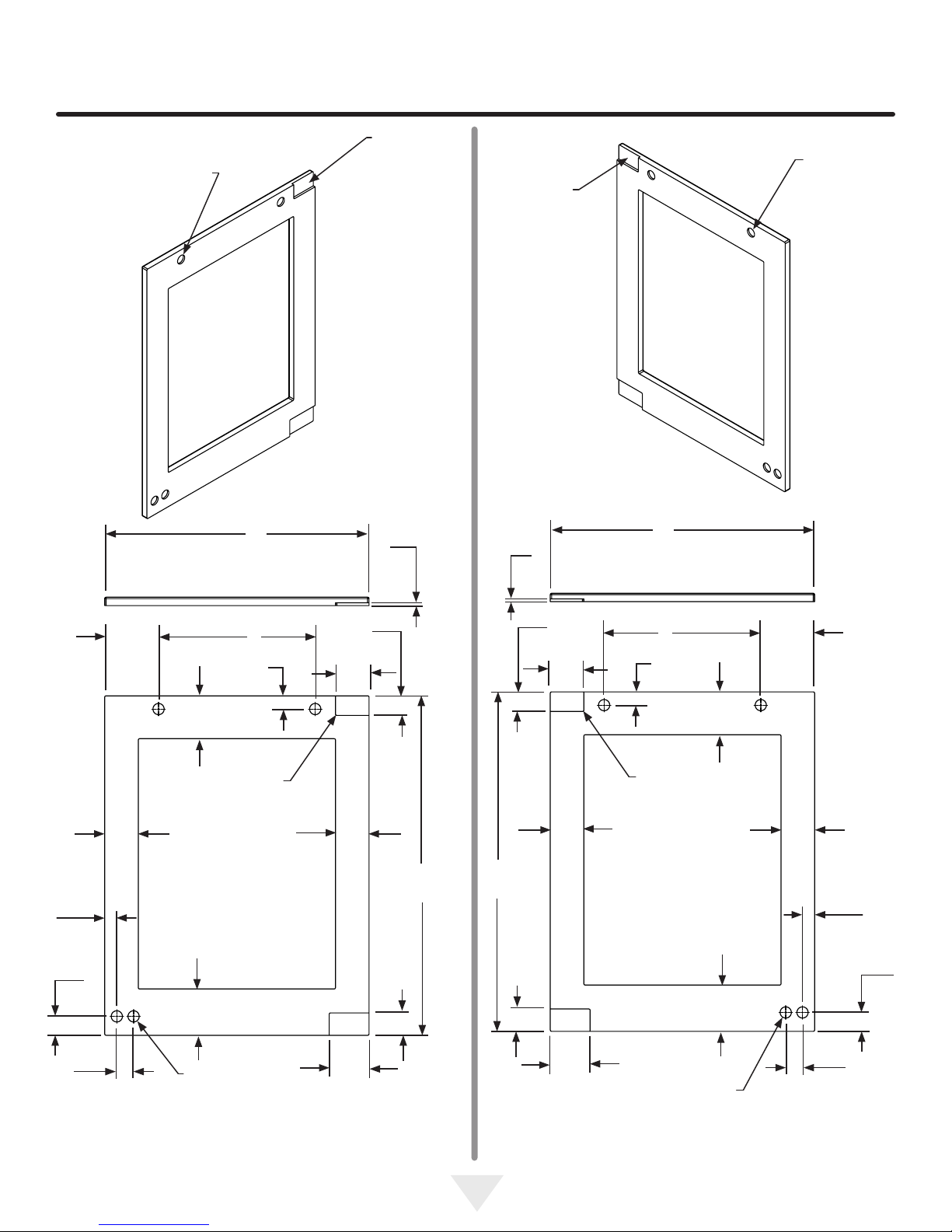
OVERLAY DOOR PANEL INSTALLATION
Clearance for
screw head,
4 places
Top of door
24" (61 cm) wide appliance
233⁄4"
(60.3 cm)
Clearance
for hinge
at top and
bottom
Hinge side of door
Figure 18
Left Hand Hinged Door
1
⁄4"
(6 mm)
Deep
Clearance
for hinge
Top of door
at top and
bottom
Hinge side of door
Figure 20
Right Hand Hinged Door
24" (61 cm) wide appliance
233⁄4"
1
⁄4"
(6 mm)
Deep
(60.3 cm)
Clearance for
screw head,
4 places
31⁄8"
(7.9 cm)
15⁄32"
(2.9 cm)
111⁄16"
(4.3 cm)
11⁄2"
(3.8 cm)
typical
47⁄8"
(12.4 cm)
14"
(35.6 cm)
13⁄16"
(3 cm)
327⁄32"
(9.8 cm)
1
⁄4" (6 mm)
radius is
permissible
31⁄8"
(7.9 cm)
This side
to door
41⁄8"
(10.5 cm)
1" (2.5 cm) diameter
x 1⁄4" (6 mm) deep
4 places
Figure 19
Left Hand Hinged Door
24" (61 cm) wide appliance
(4.4 cm)
31⁄8"
(7.9 cm)
311⁄16"
(9.4 cm)
13⁄4"
(5.1 cm)
3011⁄32"
(77.1 cm)
2"
15
(4.4 cm)
31⁄8"
(7.9 cm)
3011⁄32"
(77.1 cm)
2"
(5.1 cm)
13⁄4"
31⁄8"
(7.9 cm)
311⁄16"
(9.4 cm)
14"
(35.6 cm)
13⁄16"
(3 cm)
1
⁄4" (6 mm)
327⁄32"
(9.8 cm)
(12.4 cm)
radius is
permissible
This side
to door
41⁄8"
(10.5 cm)
1" (2.5 cm) diameter
x 1⁄4" (6 mm) deep
4 places
Figure 21
Right Hand Hinged Door
24" (61 cm) wide appliance
47⁄8"
31⁄8"
(7.9 cm)
15⁄32"
(2.9 cm)
111⁄16"
(4.3 cm)
11⁄2"
(3.8 cm)
typical
Page 7
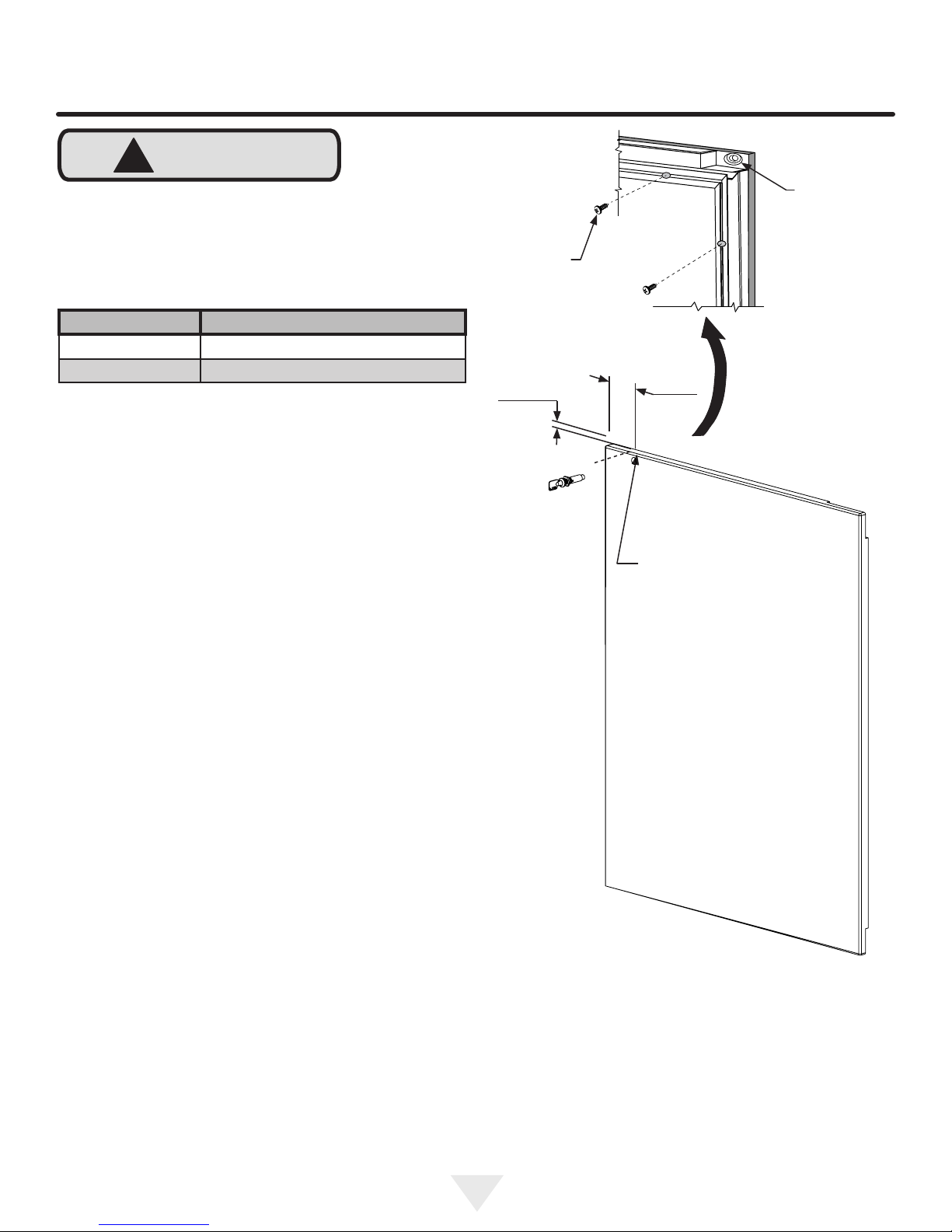
!
CAUTION
OVERLAY DOOR PANEL INSTALLATION
Weight of overlay door panel must not exceed 15
pounds (6.8 kg) for a solid door model or 10 pounds
(4.5 kg) for a glass door model.
Material Type #10 Wood Screw
Hardwood
Softwood
1
⁄8" (3.2 mm) Diameter. Pilot Hole
7
⁄64 (2.8 mm) Diameter. Pilot Hole
Table B
Step 4: Assemble the panel to the door
The preferred method of attaching the panel to the door
is to clamp the panel to the door so it cannot move while
drilling the screw pilot holes. Use bar clamps or "C" clamps
with pads on the clamping surfaces that will not mar the
panel or the door. The custom overlay panel should be
ush with the top of the door and centered along the width
of the door. See Figure 13a. Drill holes through the gasket
extrusion using the 10 holes as pilot holes. Use the drill
size from the chart in Table "B", being careful not to drill
through the front surface of the panel. If the overlay panel is
thinner than 5⁄8" (16 mm) thick shorter screws will have to be
obtained. Fasten the panel to the door with the 10 screws
provided in the literature pack. (See Figure 22a). Remove
the clamps and replace the gasket in the gasket extrusion
channels of the door. Some force may be required to seat
the gasket into the channels. Be sure the gasket corners
are seated properly.
#10 x 1⁄2"
screw
17
⁄32"
(13.7 mm)
Counter bore
lock hole
on back side.
Figure 22a
31⁄2"
(89 mm)
1
⁄2" (13 mm) diameter drill
through door panel, from
other side (see detail
above) 13⁄16" (20.5 mm)
counter bore, 7⁄16" (11 mm)
deep.
Hinge side of door
Figure 22
16
Page 8
OVERLAY DOOR PANEL INSTALLATION
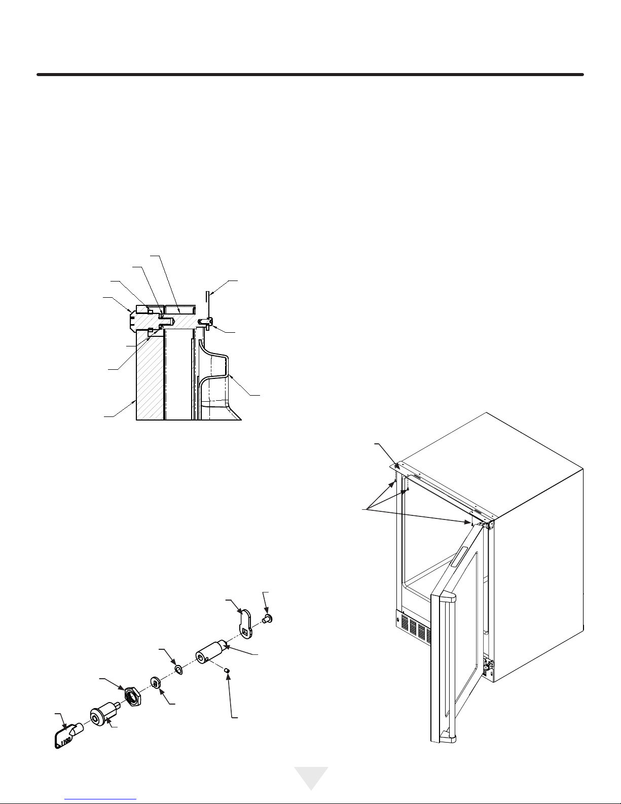
Step 5: Assemble lock parts
Two (2) lock extensions are provided with the lock. Use the
longer extension for 3⁄4" thick overlay panels and the shorter
one for 5⁄8" thick overlay panels. Assemble the lock exten-
sion, cam stop washer, spring washer, and set screw to the
lock as shown in Figure 23 and 24.
Install this lock assembly into the lock hole in the overlay
panel and secure with the retaining nut on the back side
with a 15 mm socket and ratchet. Make sure the key slot in
the front of the lock is vertical.
BRASS EXTENSION
SPRING WASHER
NUT
LOCK
1/2 HOLE
13/16 COUNTER
BORE 7/16 DEEP
CAM
PHILLIPS SCREW
Step 7: Install the door
Carefully open the top and bottom hinges on the door being
careful as there are many pinch points. Place the hinges
over the 4 screws in the cabinet, 2 at the top and 2 at the
bottom and slide the door into position. Tighten the 4 hinge
screws with a phillips screwdriver. (See Figures 11 and
11a). Place wire harness from the grille and mount to the
bottom of the door with the screw and "P" clamp removed
in step 1. (See Figure 11b). Reconnect the wire harness,
(See Figure 12).
Step 8: Secure the cabinet
Use the #8 x 3⁄4" black screws from the literature pack to
secure the counter top to the cabinet top through the holes
in the cabinet "Z" bracket.
INNER
3/4 INCH
WOOD PANEL
SECTION A-A
SCALE 1 : 1
DOOR
Figure 23
Step 6: Install lock cam
Attach the lock cam to the back of the lock assembly with
the phillips head screw provided. Orient the lock cam vertically when installing on the lock.
Screw
Brass
extension
(2 lengths
provided)
Key
Retainer
nut
Spring
washer
Lock
Cam
Cam stop
washer
Figure 24
Set screw
Cabinet
"Z" bracket
#8 x 3⁄4" black
screws
(3 places)
Figure 25
17
 Loading...