

Page 1
06/15 EINS 517026
TC/DC INTEGRATED MODULE (FFD)
(with Gas Top Burners)
For use in USA/Canada
Installation
Guide
PLEASE READ THESE INSTRUCTIONS BEFORE COMMENCING INSTALLING THIS APPLIANCE.
IMPORTANT : SAVE INSTRUCTIONS FOR FUTURE REFERENCE
IMPORTANT : CONSERVER CES INSTRUCTIONS POUR REFERENCE FUTURE
WARNING: If the information in this manual is not followed exactly, a fire or
explosion may result causing property damage,personal injury or death.
Do not store or use gasoline or other flammable vapors and liquids in the vicinity
of this or any other appliance.
WHAT DO YOU DO IF YOU SMELL GAS
. Do not try to light any appliance.
. Do not touch any electrical switch
. Do not use any phone in your building.
. Immediately call your gas supplier from a neighbors phone.
Follow the gas suppliers instructions
. If you can not reach your gas supplier call the fire department.
Installation and service must be performed by a qualified installer, service agency
or the gas supplier.
Page 2

Contents
Product Safety 3
General Notes 4
Health and Safety 4
General Installation Requirements 4
Location 5
Specification - AGA Total Control (TC3) / Dual Control (DC3) 6
with TC/DC Integrated Module (Gas Hob) (TC3M/DC3M)
Specification - AGA Total Control (TC5) / Dual Control (DC5) 7
with TC/DC Integrated Module (Gas Hob) (TC5M/DC5M)
Installation of Clearances of Combustible Cabinets adjacent to 8
range - AGA Total/Dual Control (with Module shown)
Technical Data 9
Installation 10 -11
Installation Sequence and Procedure 11 - 21
Servicing Notes 22 - 28
Circuit Diagram 29
Servicing 30
2
Page 3
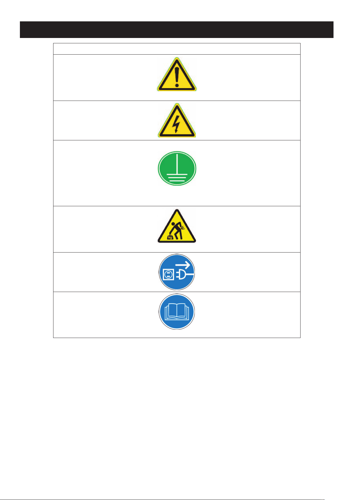
PRODUCT SAFETY
MEANING/DESCRIPTION SIGNIFICATION/DESCRIPTIONSYMBOL
WARNING/CAUTION
An appropriate safety instruction
should be followed or caution to a
potential hazard exists.
AVERTISSEMENT
Une consigne de sécurité
appropriée doivent être suivies ou
garde d’un danger potentiel
exists.
DANGEROUS VOLTAGE
To indicate hazards arising from
dangerous voltages.
TENSION DANGEREUSE
Pour indiquer les dangers
résultant des tensions
dangereuses.
PROTECTIVE EARTH (GROUND)
To identify any terminal which is
intended for connection to an external conductor for protection
against electric shock in case of a
fault, or the terminal of a protective earth (ground) electrode.
TERRE DE PROTECTION
Pour marquer bornes destin
ées à
être raccordées à un conducteur
de protection extérieur contre les
chocs éclectiques en cas de
défaut d’isolement, ou pour
marquer la borne de la terre de
protection.
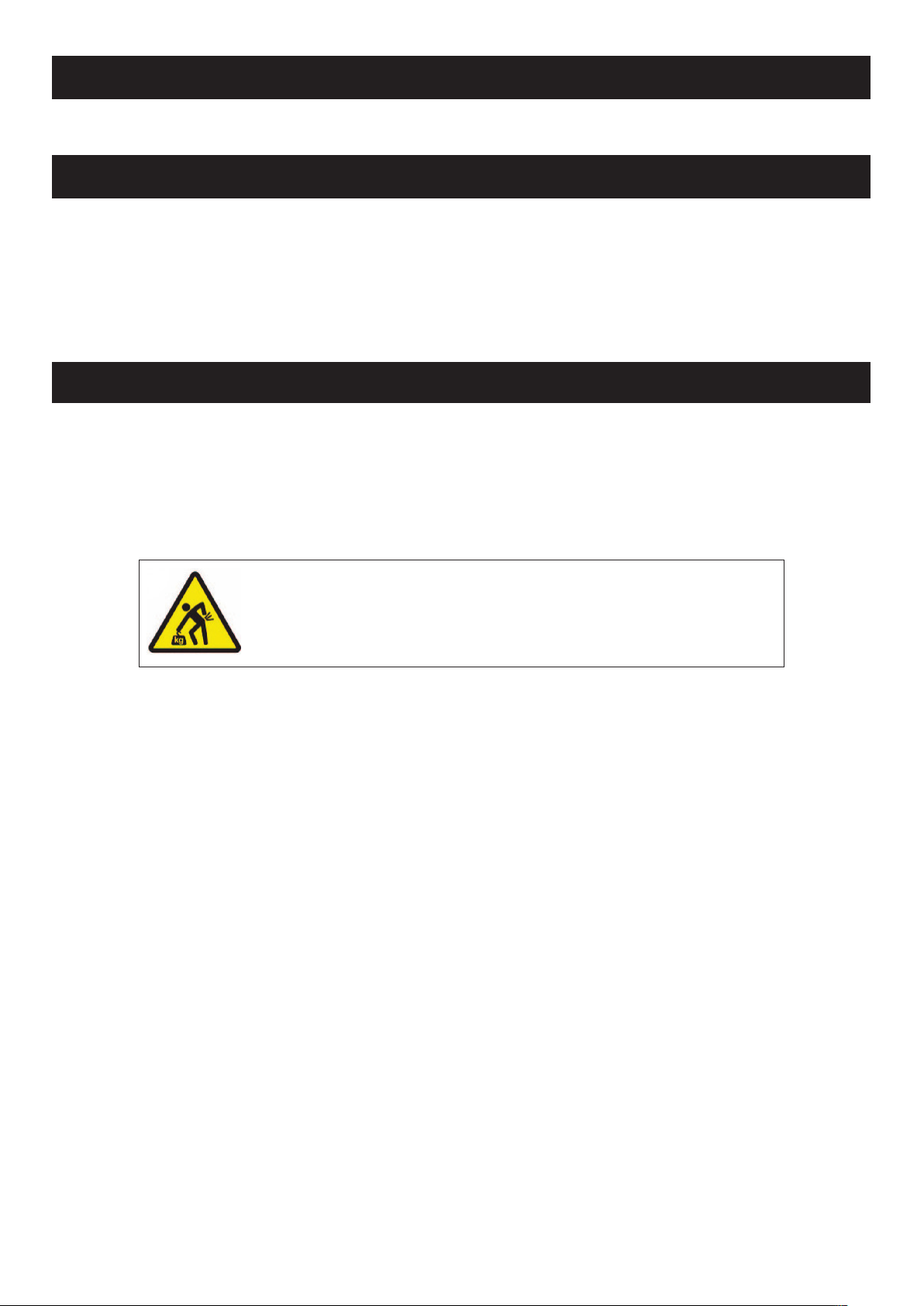
HEAVY
This product is heavy and reference should be made to the
safety instructions for provisions
of lifting and moving.
LOURD
Ce produit est lourd et doit
être
fait référence auc consignes de
sécurité relatives aux dispositions
de soulever et déplacer.
DISCONNECT MAINS SUPPLY
Disconnect incoming supply
before inspection or maintenance.
APPAREIL À LASER DE
CLASSE 2
Alimentation d’entr
ée Débrancher
avant inspection ou d’entretien.
REFER TO MANUAL
Refer to relevant instructions
detailed within the product
manual.
ATTENTION, SURFACE TRÉS
CHAUDE
Reportez-vous aux instructions
applicables, indiquées dans le
manuel du produit.
3
Page 4
HEALTH AND SAFETY
Consumer Protection
As responsible manufacturers we take care to make sure that our products are designed and constructed to meet the
required safety standards when properly installed and used.
PLEASE READ THE ACCOMPANYING WARRANTY
Any alteration that is not approved by AGA could invalidate the approval of the appliance, operation of the warranty and
could also affect your statutory rights.
GENERAL NOTES
NOTE: THESE INSTALLATION INSTRUCTIONS SHOULD BE LEFT WITH THE RANGE AND THE USER TO RETAIN
FOR FUTURE REFERENCE.
GENERAL INSTALLATION REQUIREMENTS
The installation of the range must be in accordance with the relevant requirements of the local Wiring and Building
Regulations. It should be in accordance also with any relevant requirements of the Local Authority.
In your own interest and that of safety to comply with the law, all appliances should be installed by an authorized AGA
distributor in accordance with the relevant regulations.
CAUTION:
THIS UNIT IS HEAVY, PROPER EQUIPMENT AND ADEQUATE
MANPOWER MUST BE USED IN MOVING THE RANGE TO
AVOID DAMAGE TO THE UNIT OR THE FLOOR
4
Page 5

REFER TO FIG 1 & 2
The side wall clearance above the hob shall be greater than 3”.
Surfaces over the top of the range must not be closer than 30” and must not exceed 13” in depth.
The vent slots in the back of the top plate (or shroud) must not be obstructed.
Note: It is essential that the supply cable is routed away from any hot surfaces i.e. hot flue pipes.
In the interests of safety, due consideration must be given to the protection of the electric cable to the Module/Companion.
The AGA TC/DC Integrated Module (Gas Hob) requires a 30 amp power supply and must be connected to the mains with
a cable which complies with the latest edition of the Local and National Wiring Regulations.
Remember that an excess of cable length is required for the possible withdrawal of the range.
A electrical socket type 14-30R must be provided within 5 feet of the left hand side of the range and accessible for
disconnection.
DO NOT position socket above or behind the range.
An easily accessible manual shut off gas valve must be fitted before the metal flexi gas line supply to the range. DO NOT
fit valve behind the range.
Any opening in the wall behind the appliance and in the floor under the appliance must be sealed.
LEVELLING
The AGA TC/DC Integrated Module (Gas Hob) is designed to stand on a flat surface, however any unevenness may be
overcome by packing under the corners of the plinth with a suitable non-combustible material, (up to 1/8”).
LOCATION
5
Page 6
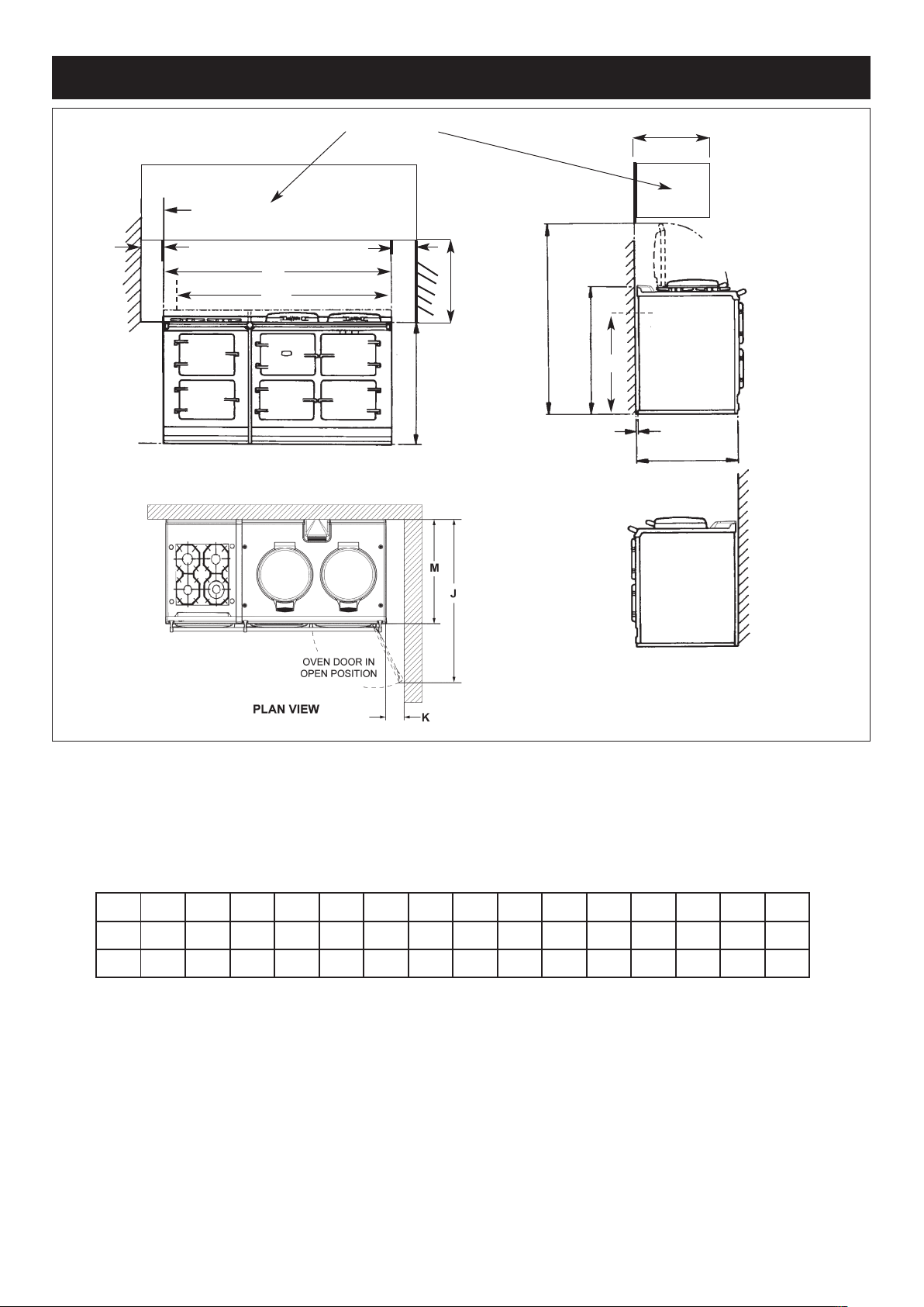
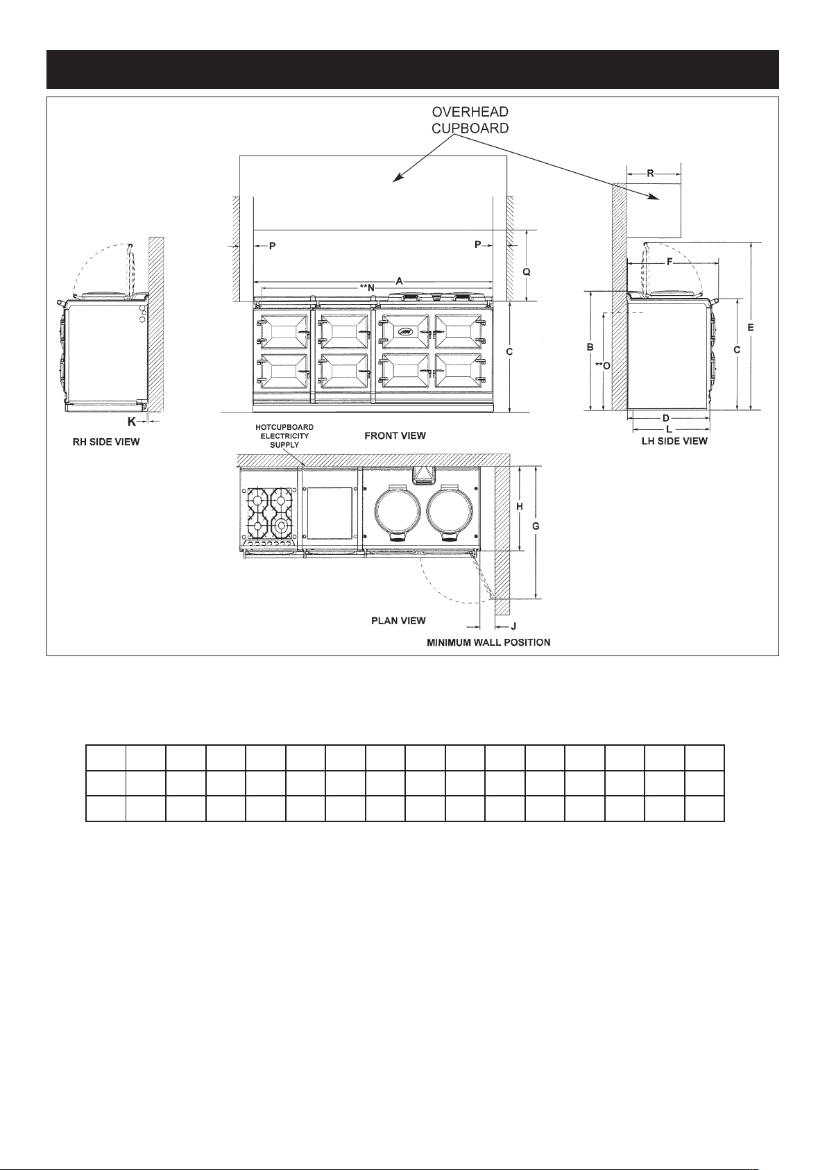
SPECIFICATION - AGA TOTAL CONTROL (TC3) / DUAL CONTROL (DC3) WITH
TC/DC MODULE (GAS HOB) (TC3M/DC3M)
The extension channel section at the rear of each side plate may be removed, if required to clear flue pipes.
COOKER DIMENSIONS
When surveying for a range cooker installation the actual clearance required for the ‘body’ of the appliance should be
increased overall by
3
/8” (10mm) beyond the figures quoted. This allows safe margin to take into account the natural
dimensional variations found in major castings. In particular the width across an appliance recess could be critical.
C
E
P
E
D
L
Q
B
G
POSITION OF LIDS
WHEN RAISED
OVERHEAD
CUPBOARD
** POSITION FOR GAS SUPPLY PIPE TO MODULE
A B C D E G H J K L M **N **O P Q
mm 1589 948 910 679 75 1330 756 1125 116 3 698 1533 800 760 330
ins 62
9
/16
37
3
/8
35
7
/8
26
3
/4
3 51
3
/4
29
3
/4
44
1
/4
4
1
/21/8
27
1
/2
60
5
/8
31
1
/2
30 13
6
**O
Fig. 1 DESN 517031
**N
A
Page 7
SPECIFICATION - AGA TOTAL CONTROL (TC5) / DUAL CONTROL (DC5) WITH
TC/DC MODULE (GAS HOB) (TC5M/DC5M)
Fig. 2 DESN 517033
COOKER DIMENSIONS
When surveying for a range cooker installation the actual clearance required for the ‘body’ of the appliance should be
increased overall by
3
/8” (10mm) beyond the figures quoted. This allows safe margin to take into account the natural dimen-
sional variations found in major castings. In particular the width across an appliance recess could be critical.
7
A B C D E F G H J K **N **O P Q R
mm 2084 948 910 679 1330 760 1125 698 116 3 2220 800 3 760 330
ins 821/16
373/8
357/8
263/4
513/4
5115/16
441/4
271/2
41/21/8
873/8
311/21/8
30 13
**POSITION FOR GAS SUPPLY PIPE TO MODULE
Page 8
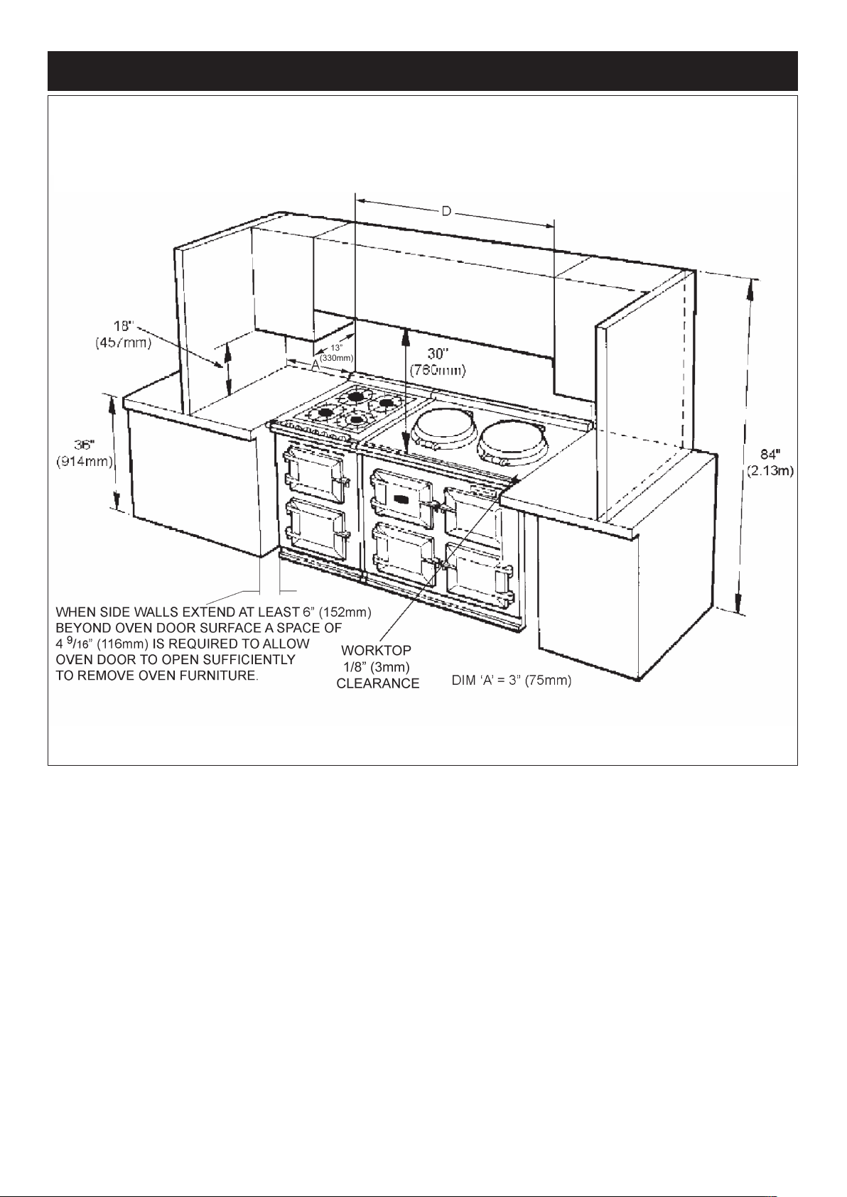
INSTALLATION CLEARANCES OF COMBUSTBLE CABINETS ADJACENT TO
RANGE AGA TOTAL/ DUAL CONTROL (WITH MODULE SHOWN)
Installation Clearance of Combustible Cabinets Adjacent to Range
1/2” CLEARANCE TO THE BACK OF THE RANGE MAY BE OBTAINED WHEN INSTALLING THE APPLIANCE
AGAINST A NON-COMBUSTIBLE WALL OR IF THE WALL BEHIND THE RANGE IS DEEMED COMBUSTIBLE THEN
THE MINIMUM SPACING FROM THE BACK OF THE APPLIANCE TO THE NEAREST COMBUSTIBLE WALL IS
1 1/2”
(38mm).
8
Fig. 3 DESN 517032
Page 9
HOTPLATE
NATURAL GAS
R.H.F. L.H.R. R.H.R. L.H.F.
BURNER TYPE ULTRA RAPID RAPID SEMI-RAPID SEMI-RAPID
(WOK)
MAXIMUM HEAT 3.5 kW 3.1 kW 1.8 kW 1.8 kW
INPUT 12,000 Btu/hr 10,600 Btu/hr 6,150 Btu/hr 6,150 Btu/hr
INJECTOR MARKING 170 155 118 120
PRESSURE POINT POSITION: FRONT LH HOTPLATE INJECTOR
PRESSURE SETTING: 4” wg
BURNER IGNITION: H.T. SPARK
PROPANE
R.H.F. L.H.R. R.H.R. L.H.F.
BURNER TYPE ULTRA-RAPID RAPID SEMI-RAPID SEMI-RAPID
(WOK)
MAXIMUM HEAT 12,000 Btu/hr 10,600 Btu/hr 6.150 Btu/hr 6.150 Btu/hr
INPUT 3.5 kW 3.1 kW 1.8 kW 1.8 kW
(250g/h) (221g/h) (128g/h) (128g/h)
(0.5l/h) (0.43l/h) (0.26l/h) (0.26l/h)
INJECTOR MARKING 105 94 72 75
PRESSURE POINT POSITION: FRONT LH HOTPLATE INJECTOR
PRESSURE SETTING: 10” wg
BURNER IGNITION: H.T. SPARK
ELECTRIC GRILL & OVENS 240 VOLT 60 Hz SINGLE PHASE 30 AMP
GRILL ELEMENT - POWER RATING 2 x 1.05 kW
TOP OVEN - POWER RATING 1.0 kW
LOWER OVEN (FANNED CONVECTION) - 1.9 kW
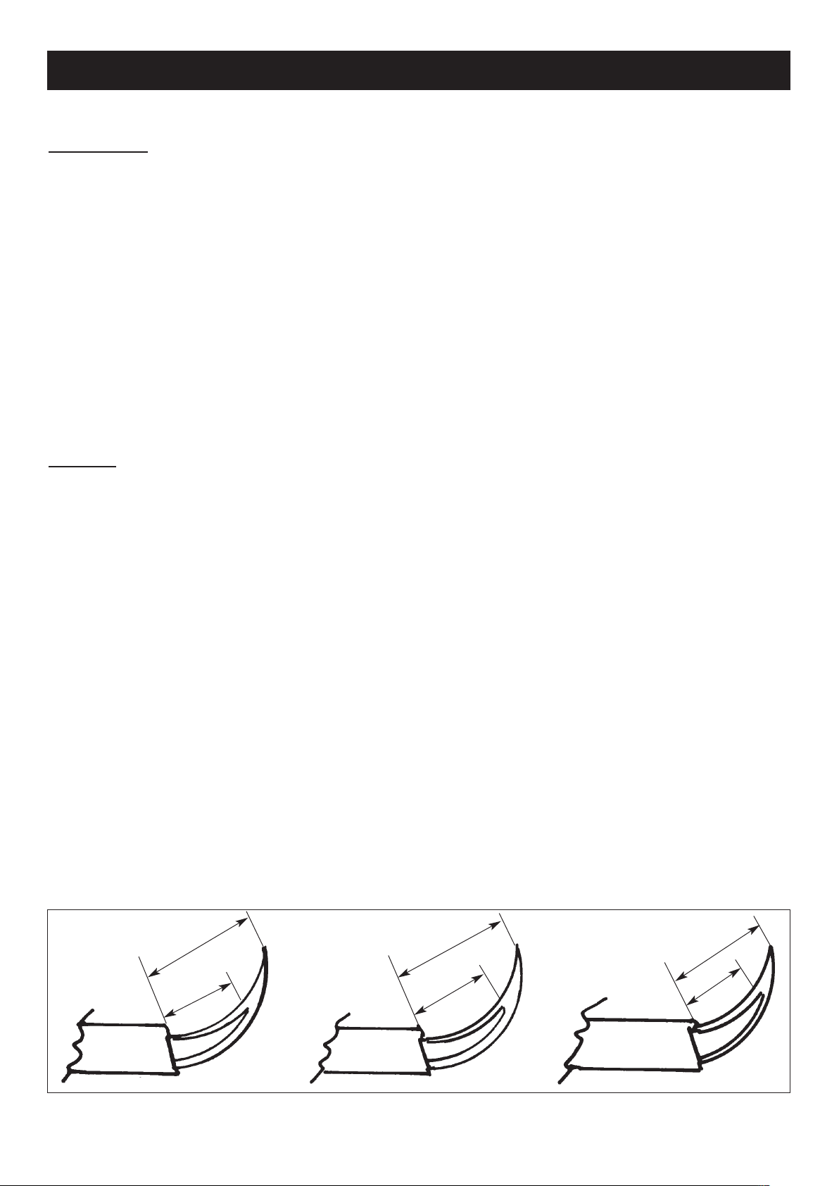
TYPICAL SECTION VIEW OF BURNER FLAMES
TECHNICAL DATA
9
11/16”
15/16”
9/16”
7/8”
1/2”
7/16”
11mm
17.5 mm
24 mm
14 mm
22 mm
12.5 mm
FRH HOTPLATE BURNER
RLH HOTPLATE BURNER
RLH & FRH HOTPLATE BURNER
Page 10

CAUTION: THIS INSTALLATION MUST CONFORM WITH LOCAL CODES OR, IN THE ABSENCE OF LOCAL CODES
WITH THE NATIONAL FUEL GAS CODE ANSI.Z223.I AND NATIONAL ELECTRICAL CODE ANSI/NFPA70 (IN CANADA
CAN/CGA-B149) AND ONLY USED IN A WELL VENTILATED SPACE, READ THE INSTRUCTIONS BEFORE
INSTALLING OR USING THIS APPLIANCE.
PRIOR TO INSTALLATION, ENSURE THAT THE LOCAL DISTRIBUTION CONDITIONS (NATURE OF THE GAS AND
GAS PRESSURE) AND THE ADJUSTMENT OF THE APPLIANCE ARE COMPATIBLE.
THE ADJUSTMENT CONDITIONS FOR THIS APPLIANCE ARE STATED ON THE DATA PLATE.
THE GAS ADJUSTMENT CONDITIONS FOR THIS APPLIANCE ARE STATED ON THE DATA PLATE WHICH IS SITUATED IN THE CENTRE VENT SLOT NEAR THE BASE OF THE FRONT PLATE.
CAUTION: THIS UNIT IS HEAVY, PROPER EQUIPMENT AND ADEQUATE MANPOWER MUST BE USED IN MOVING
THE RANGE TO AVOID DAMAGE TO THE UNIT OR THE FLOOR.
This appliance is not connected to a combustion products evacuation device. It shall be installed and connected in
accordance with current installation regulations. Particular attention shall be given to the relevant requirements regarding
ventilation.
It should be in accordance also with any relevant requirements of the Gas Region and Local Authority.
The appliance and its individual gas shut off valve must be disconnected from the gas supply piping system during any
pressure testing of that system test pressure in excess of 1/2 psi (3.5 kPa).
The appliance must be isolated from the gas supply piping system by closing its individual manual shut off valve during any
pressure testing of the gas supply system at test pressures equal to or less than 1/2 psi (3.5 kPa).
On completion test the gas installation for soundness and purge. Leak testing of the appliance shall be conducted according
to the manufacturers instructions.
NOTE: Use soapy water solution on new gas connections to ensure there are no gas leaks.
WARNING: ELECTRIC SHOCK HAZARD
It is the customers responsbility to contact a qualified electrical installer to make sure the electrical installation is adequate
and in conformance with National Electrical Code ANSI/FPA 70- latest edition, and all local codes and ordinances.
Take special care when cutting holes in walls or floor. Electrical wires may be behind the wall or floor covering and could
cause an electrical shock if you touch them.
Locate any electrical circuits that could be affected by the installation of this product and disconnect power circuit.
Electrical grounding is required on this appliance.
Do not have a fuse in the neutral or grounding circuit. A fuse in the neutral or grounding circuit could result in electrical
shock.
Do not use an extension lead with this appliance.
Check with a qualified electrician if you are not sure the appliance is properly grounded .
Failure to follow these instructions could result in death or serious injury.
In the interest of safety, due consideration must be given to the protection of the electric cable to the module.
INSTALLATION
10
Page 11

The range is installed adjacent to the LH side of an AGA Total Control/AGA Dual Control.
Installation of the Module must, therefore be in conjunction with the build instructions of the ‘parent’ AGA Total Control/AGA
Dual Control.
Reference must be made to the above Installation Instructions for the ‘parent’ AGA especially regarding pre-site inspection,
not only for both cookers but to consider any pipework that may pass at the rear of the Module. i.e. vent pipe from ‘parent’
AGA.
The appliance has been designed to accommodate pipework passing at the rear.
NOTE! THE MAIN AGA TOTAL CONTROL/ AGA DUAL CONTROL IS DELIVERED EX-WORKS FULLY ASSEMBLED.
FINAL INSTALLATION IS UNDERTAKEN ON SITE, BY AN AUTHORISED AGA ENGINEER.
The AGA TC/DC Module is supplied from the manufacturers in a fully assembled condition.
11
INSTALLATION SEQUENCE AND PROCEDURE
Installation must be to Local and National Wiring Regulations and carried out by a Qualified Engineer.
Having ensured all space requirements and regulations have been satisified for the combined arrangement (AGA Total /
Dual Control and Module), the build and installation is to proceed as follows:-
1. It is essential that the base or hearth on which both range and module stands should be level and capable of
supporting the total weight of the appliance.
AGA Total Control (TC3) = 816 lbs (370kgs) AGA Dual Control - Gas (DC3G) = 996 lbs (452kgs)
Hotcupboard (TC5 / DC5) = 242 lbs (110kgs) AGA Dual Control - Electric (DC3E) = 978 lbs (444kgs)
Module = 284 lbs (129kgs)
2. Unpack and remove the Module from the pallet.
3. Check that the rear extension piece is secured to the left hand side panel.
4. Release 2 screws from front tongue bracket and allow the bracket to drop downwards. Now slide the Module off its plinth
and set to one side.
Fig. 4 DESN 516863
Page 12

5. The Module plinth can now be levelled and fitted up to the main appliance. Position the Module plinth alongside the
AGA TC3/DC3 leaving no gap betweem the two plinths. (See Fig. 6).
When fitting the Module onto an AGA TC5/DC5 there should be a gap of
11
/64” (4.5mm) (See Fig. 5).
PLEASE NOTE: When fitting a Module plinth to an AGA TC5 or AGA DC5 the 2 adjustment screws should be screwed
in from the outside (until they are fully in). The screw heads will set a gap of 11/64” (4.5mm) between plinths.
Fig. 5 DESN 516859
11
/64” (4.5 mm)
SCREW HEAD DEPTH
Check with a spirit level that the plinth is correct and using a straight edge check that both plinths are aligned along the
front face (using either front or rear plinth adjustment screw to alter alignment, if necessary).
Also check height differential between the Module plinth and AGA Total/Dual Control plinth is correct
3
/8” (11mm) (See
Fig. 6 or 6A). If necessary, use the adjusting studs in each corner to level the plinth. In extreme instances, shims may
be used underneath the plinths .
Fig. 6 DESN 516276
MODULE PLINTH
BASE
3
/8” 11mm
HEIGHT
DIFFERENTIAL
FOR AGA TC3/DC3 + MODULE ONLY
12
Page 13

Fig. 6A DESN 516276
MODULE PLINTH
BASE
3
/8” (11mm)
HEIGHT
DIFFERENTIAL
HOTCUPBOARD
PLINTH BASE
11
/64” (4.5 mm)
GAP
FOR AGA TC5/DC5 + MODULE ONLY
6. Attach Module plinth to the AGA Total/Dual Control plinth using 2 M6 screws and washers provided (See Fig. 7 or 7A).
Slide front jointing bracket into place over two pot magnets, locking the two appliances together.
Fig. 7 DESN 516852
FOR AGA TC3/DC3 + MODULE ONLY
13
Page 14

Fig. 7A DESN 516858
FOR AGA TC5/DC5 + MODULE ONLY
7. Prior to electrical connections, remove top plate assembly from Module as follows:-
a) Remove pan supports and all controls knobs.
b) Remove four chrome buttons and the four top plate retaining screws (2 each side).
c) Remove two screws from control panel (one from left hand hole and one from centre hole). (See Fig. 8).
d) Pull top plate forward slightly and lift up at front. Support top plate and disconnect wiring to the two neons. Remove
top plate.
e) Lay the top plate on its top face, suitably protected.
DESN 511645
REMOVE 2 FIXING SCREWS
Fig. 8
14
Page 15

15
8. Check current is OFF.
Connect mains wire to terminal block at the rear of the cooker (See Fig. 9). Sufficient cable should be available to allow
cooker to be removed for service.
Electrical Connections
Electric Shock Hazard
Electrical grounding is required on this range.
Do Not connect to the electrical supply until the range is permanently grounded.
Disconnect the power to the junction box before making the electrical connection.
This range must be connected to a grounded, metallic, permanent supply or a grounding connector should be
connected to the grounding terminal or wire lead on the range.
Do Not ground to gas pipe. Failure to follow these instructions could result in death or serious injury.
l A four-wire single phase 240-volt, 60-Hz, AC-only electrical supply is required on a separate, 30-amperes circuit, fused
on both sides of the line.
l A time-delay fuse or circuit breaker is recommended.
l Local codes permit the use of a U.L.-listed, 250-volt, 30-amperes power cord (pigtail). This cord contains four No. 10
copper wires and matches a four-wire receptacle of type 14-30R shown in Fig. 9. Connectors on the appliance end
must be provided at the point the power supply enters the appliance.
Wire sizes (COPPER WIRE ONLY) and connections must conform with the rating of range (30- amperes).
l The wiring diagram is located on the back of the range.
Page 16

11. Assemble a U.L.-listed strain relief in the opening.
12. Insert the power supply cord through the strain relief, allowing enough slack to easily attach the wiring to the terminal
block.
13. Use only ring-type terminals to connect the power supply. To secure the power supply cord use 6mm (1/4”) brass
terminal nuts attached to the inside of the terminal block cover. Be sure nuts are installed tight.
14. Complete electrical connection.
L1
WHITE
(NEUTRAL)
GREEN
(GROUND)
L2
Fig. 9
DESN 511752
16
9. Remove the terminal block cover screws located on the back of the range.
10. Make the four-wire connection following the “Power supply cord method”.
Power supply cord method
This range is manufactured to use a four-wire power supply cord rated at 250-volts, 30-amperes (See “Four wire electrical
connection”).
Page 17

Fig. 10 DESN 517044
15. Apply tape (provided) to the rear of the lap strip on the Module front plate.
16. Slide Module onto plinth until rear tongue bracket engages fully into rear of base slot. (See Fig. 10). Ensure the
appliance is aligned squarely with the plinth. Check that the Module front plate and AGA Total/Dual Control front plate
are the same height, and that the overlap strips correspond correctly. If not, adjustment should be made to the relevant
appliance at this stage.
Then proceed to engage the front tongue bracket into the slot on the underside of the base plate, and lock into place
by tightening the two M6 screws fully.
17
Page 18

Fig. 11A
DESN 517034
AGA DC3G (Power Flue) Gas Supply Connections
(Approximate Positions)
Fig. 11
DESN 517042
Gas Supply Connections
MODULE GAS SUPPLY CONNECTIONS
The cooker must be installed by connection to rigid
pipework, which should not be less than
9
/16” (15mm)
diameter.
Connection is made to the 9/16” (15mm) compression
fitting located just below the hotplate level on the rear left
hand side of the cooker.
a. Mark off appropriate position on wall for gas supply to
cooker. See Fig. 1 or 2 and Fig. 11.
b. Isolate the gas supply and connect pipework as
required up to the position marked.
c. Check for gas tightness after connecting gas supply to
the module.
Gas Connections
18
Page 19

Fig. 12 DESN 517045
GAS ADJUSTMENT FOR
NATURAL GAS/PROPANE
Pressure Testing
The maximum gas inlet pressure to the appliance must not exceed 12” wg for N.G. and 14” for L.P. Gas. The minimum gas
inlet pressure at the appliance must not be less than 5” w.g. Natural Gas and 11” wg L.P. Gas to enable the correct manifold
pressure to be obtained.
NOTE: The regulator is pre-set for either N.G. or L.P. Gas.
Use the small hotplate burner injector as the pressure test point.
For Natural Gas manifold pressure is 4” w.g.
For L.P.G. (Propane Only) manifold pressure 10” w.g.
19
Page 20

17. Replace Module top plate as follows:
a) Support top plate at front and reconnect the wiring to the two neons.
b) Carefully lower the top plate into position taking care not to damge wiring or neons.
c) Ensure holes for controls spindles are aligned correctly, and replace 2 screws into control panel.
d) Loosely screw the top plate down with 4 retaining screws.
18. Verify that the two plates are level, then proceed with tightening down.
19. Fit the Module handrail bracket over the fixing stud located on the top plate. Lock into position by tightening the grub
screw nearest the appliance. (See Fig. 13).
Fig. 13 DESN 516855
20. Next, fit allthread stud into the insert located in the one end of the Module handrail, then feed the handrail through the
bracket and screw the handrails together. (See Fig. 14).
Fig. 14 DESN 516856
20
Page 21

21. Once the handrail assembly is located squarely, lock the handrail in position by tightening the grub screws on the
underside of each handrail bracket.
22. Once the handrails are locked in position, fit the handrail endcaps. The endcaps should be carefully pushed into place
until they sit flush with the outside face of each bracket (a light smear of lubricant such as, hand soap on the end cap
‘O’ rings may ease fitment.
23. Finally, fit the plinth facia to the magnets on the front of the plinth, making sure that the right hand side of the Module
plinth facia sits against the left hand side of the AGA Total Control or AGA Dual Control plinth facia leaving no gap
between. Also,make sure that the plinth facias are centrally located and do not overhang either appliance.
(See Fig. 14).
Commission the AGA Total Control or AGA Dual Control, as stated in the relevant Installation Instructions and carry out
functional test on each of the features of the Module.
21
Page 22

DISCONNECT FROM ELECTRICITY SUPPLY BEFORE SERVICING.
WHEN RE-WIRING ANY ELECTRICAL COMPONENTS REFER TO CIRCUIT DIAGRAM AND ELECTRICAL SCHEMATIC
DIAGRAM ATTACHED BEFORE ELECTRICAL RECONNECTION CHECK THAT THE APPLIANCE IS ELECTRICALLY
SAFE.
NOTE: TURN OFF GAS SUPPLY TO RANGE BEFORE SERVICING ANY GAS CARRYING COMPONENTS. ALWAYS
CHECK APPLIANCE FOR GAS SOUNDNESS AFTER COMPLETION.
NOTE: USE SOAPY WATER SOLUTION TO ENSURE THERE ARE NO GAS LEAKS.
A. REMOVAL OF TOP PLATE
1. Disconnect from electricity supply and remove pan supports and control knobs.
2. (a) Remove the handrail from the module top plate.
(b) Remove shroud (if fitted) from rear of top plate.
(c) Remove four chrome buttons and the four top plate retaining screws (2 each side).
3. Remove left hand and centre grommets from the control panel to gain access to the fixing screws.
Remove two screws from control panel (one from left hand hole and one from centre hole (See Fig. 8).
4. Carefully pull top plate forwards slightly and lift up at the front. Support top plate and disconnect the wiring to the neons.
Remove top plate.
5. Lay the top plate on its top face, suitably protected.
6. Re-assemble in reverse order.
B. REMOVAL OF HOTPLATE
1. Repeat operations 1 to 5 of section ‘A’.
2. Remove burner heads and burner caps.
3. Remove all of the screws retaining hotplate burner trims (4 from the Wok burner, 2 each from the other three burners).
4. Carefully remove burner trims and gaskets, taking care not to damage gaskets or burner electrodes.
5. Disconnect earth wire from left hand control panel mounting bracket.
6. Remove hotplate.
7. Re-assemble in reverse order, ensuring burner heads and burner caps are correctly located and electrodes are not
damaged. (See Figs 15, 15a, 15b).
C. TO CHANGE IGNITION GENERATOR
1. Turn off electricity supply.
2. Remove top plate and hotplate (See sections A and B).
3. Remove two screws retaining the generator fixing bracket to the burner mounting panel, and remove generator.
(See Fig. 16).
4. Carefully remove all wiring from ignition generator (Fig. 16).
5. Re-assemble in reverse order and check operation of ignition to hotplate burners.
SERVICING NOTES
22
Page 23

D. TO CHANGE IGNITION ELECTRODE
1. Turn off electricity supply.
2. Remove top plate and hotplate, (See sections A and B).
3. Disconnect the electrode cable from the ignition generator.
4. Remove spring clip retaining electrode to burner body (See Fig. 17) and remove electrode and cable.
5. Replace with new electrode ensuring spring clip is correctly located into burner body.
6. Re-assemble in reverse order and check operation of ignition to hotplate burners.
E. TO CHANGE HOTPLATE GAS TAP
1. Turn off gas supply and electricity supply.
2. Remove top plate and hotplate (see sections A and B).
3. Remove controls mounting plate by removing the 6 screws. (As shown in Fig. 18).
4. Disconnect supply pipes from rest of all 4 gas taps and pull wiring off tap switches.
5. Disconnect gas rail tube and remove 4 screws from gas rail support brackets. (See Fig. 19).
6. Remove gas rail/taps assembly and remove appropriate tap by removing 2 screws. (See Fig. 20).
7. Re-assemble in reverse order ensuring that the sealing ring is correctly located between the new tap and the gas rail.
(Rewire as circuit diagram).
8. Check for gas soundness before fitting hotplate and top plate.
9. When re-assembled, check for correct operation of tap/tap ignition switches.
F. TO CHANGE OVEN THERMOSTAT/GRILL CONTROL
1. Turn off electricity supply.
2. Remove hotplate and top plate (see sections A and B).
3. Remove two screws retaining the thermostat/grill control to the controls panel.
4. Pull all of the wiring off the thermostat or grill control. The grill control can now be removed.
5. From inside the oven, unclip thermostat phial.
(Top oven phial located at rear of oven; lower oven phial located at top right hand side).
6. Feed phial through hole in oven, then pull capillary up from side of range to remove thermostat.
7. Re-assemble in reverse order, ensuring thermostat phial and capillary are not damaged and phial is correctly
located into retaining clips. (Rewire as circuit diagram).
8. Check operation of oven thermostat phial or grill control.
23
Page 24

Fig. 15 DESN 511617
BURNER CAP
RETAINING LUGS
Fig. 15A DESN 513513
DESN 513898Fig. 15B
24
Page 25

Fig. 16 DESN 517047
SPARK
GENERATOR
TERMINAL
BLOCK
25
Access to the gas governor is as follows:-
a) Remove pan supports and all control knobs.
b) Remove four chrome buttons and the four plate retaining screws (2 each side).
c) Remove left hand and centre grommets from the control panel to gain access to the fixing screws. Remove two
screws from control panel (one from left hand hole and one from centre hole). (See Fig. 8).
d) Pull top plate forwards slightly and lift up at front. Support top plate and disconnect wiring to the two neons. Remove top
plate.
e) Lay the top plate on its top face, suitably protected.
GAS ADJUSTMENT FOR
NATURAL GAS/PROPANE
Page 26

Fig. 17
Fig. 18
DESN 511649
DESN 511650
26
Page 27

Fig. 19
Fig. 20
DESN 511651
DESN 511652
GAS RAIL
SUPPORT BRACKET
SCREWS
GAS RAIL
SUPPORT BRACKET
SCREWS
GAS TAP
TUBE NUT
GAS RAIL
TUBE NUT
27
Page 28

CAUTION: LABEL ALL WIRES PRIOR TO DISCONNECTION WHEN SERVICING CONTROLS WIRING ERRORS CAN
CAUSE IMPROPER AND DANGEROUS OPERATION.
VERIFY PROPER OPERATION AFTER SERVICING
NOTE: 1. IGNITION SWITCHES AND THERMOSTATS ARE SHOWN
IN THE OFF POSITION WITH THE APPLIANCE COLD
AND FAN OVEN DOOR IS CLOSED.
2. THE COOKER IS COLD
(IE. CUT-IN & CUT-OUT NOT OPERATED)
28
Page 29

AGA TC/DC INTEGRATED MODULE (GAS HOB)
CIRCUIT DIAGRAM
29
Page 30

30
l In the event of your appliance requiring maintenance please call AGA Service or contact your authorised
distributor/stockist.
l Your cooker must only be serviced by a Qualified Engineer from an authorised distributor or stockist.
l Do not alter or modify the cooker.
l Only the spares specified by the manufacturer are to be fitted.
SERVICING
Page 31

31
Page 32

www.agamarvel.com
Supplied by
AGA Marvel
1260 E. Van Deinse St.
Greenville, MI 48838
Business (616) 754-5601
Fax (616) 754-9690
Toll Free Telephone 800-223-3900
With AGA Marvel’s policy of continuous product im-
provement, the Company reserves the right to
change specifications and make modifications to
the appliance described and illustrated at any time.
For further advice or information contact
your local AGA Specialist
32
 Loading...