

Page 1
AGA TOTAL CONTROL
TC3
User Guide &
Installation Instructions
REMEMBER, when replacing a part on this appliance, use only spare parts that you can be assured conform to the safety and
performance specication that we require.
DO NOT use reconditioned or copy parts that have not been clearly authorised by AGA.
PLEASE READ THESE INSTRUCTIONS BEFORE USING THIS APPLIANCE
PLEASE READ THESE INSTRUCTIONS BEFORE USING THIS APPLIANCE
AND KEEP IN A SAFE PLACE FOR FUTURE REFERENCE.
AND KEEP IN A SAFE PLACE FOR FUTURE REFERENCE.
For use in USA & CAN
07/17 EINS 516294
Page 2
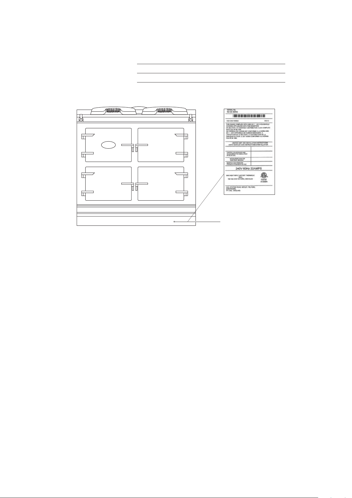
Make a note of your AGA Total Control Serial Number when it is being installed. The serial number can be found behind the
Data badge located
magnetic plinth cover.
My AGA Details:
Serial No:
AGA Service No:
Date of Installation:
behind removable
plinth
Page 3

Contents
1. Product Safety 1
2. Health & Safety 3
3. Introduction 5
4. Overview 6
5. Operating the AGA Total Control 7
Getting started 8
General Advice 9
Handset Fig. 5.2 10
Handset Advice 10
Communication/Handshake 11
Date and Time Setting 12
Auto/Events program screen 12
Information (Home) Screen 13
6. AGA Accessories 15
Fitting the Oven Shelves 17
Removing the Oven Shelves 17
10. Installation Instructions 27
11. Installation Introduction 28
12. Location 29
13. Connection to the Power Supply 32
14. Circuit Diagram AGA TC3 34
15. Warranty 35
16. Service 37
7. The Ovens 18
The Roasting Oven 19
The Baking Oven 20
Slow Cook Oven 21
Using the zones of the AGA Total Control 22
The Plates 22
Fitting the Doors 23
Removing the Doors 23
8. Cleaning & Caring for
your Range 24
9. Troubleshooting 26
Page 4

Page 5
1. Product Safety
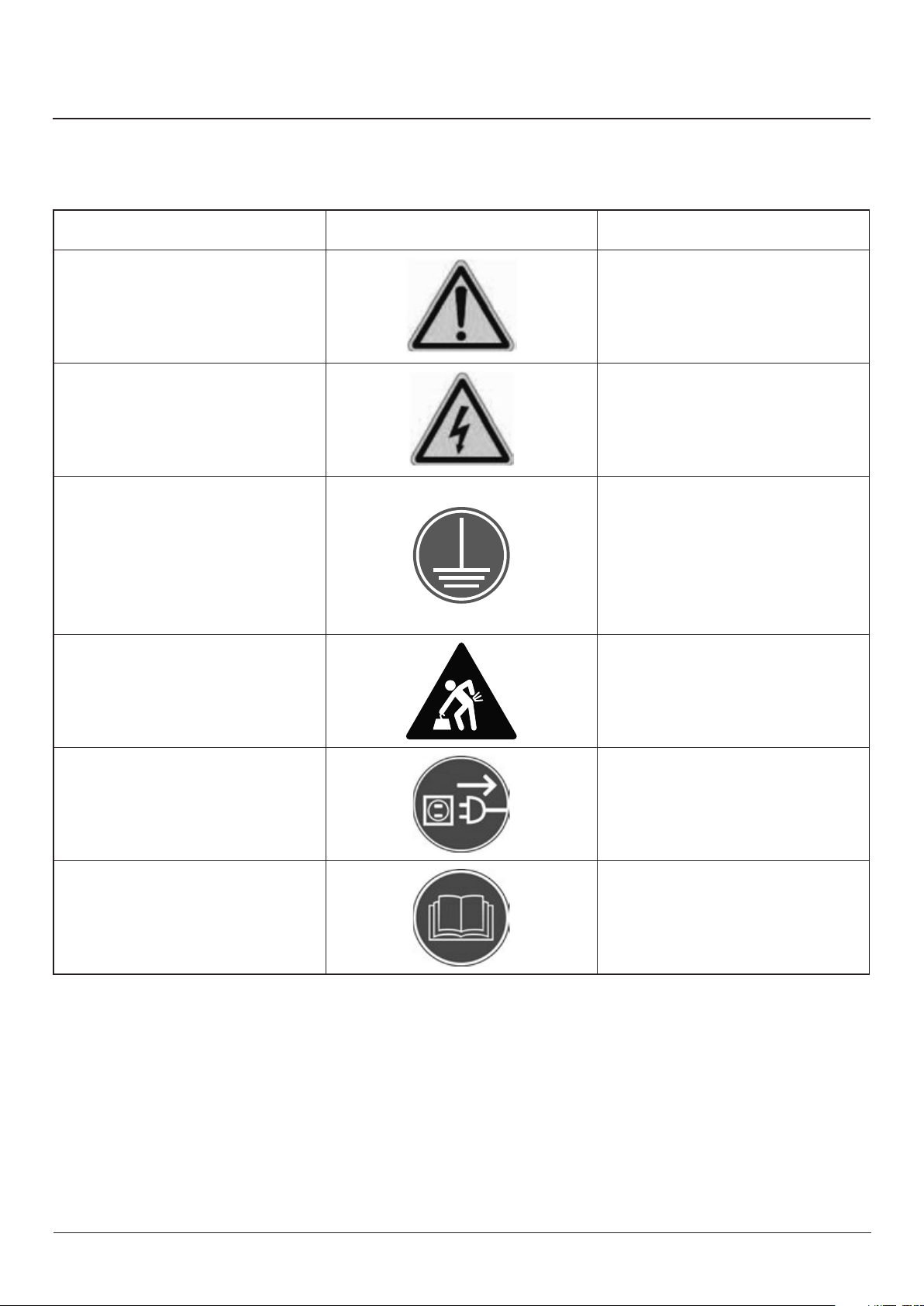
Meaning / Description Symbol Signication / Description
WARNING / CAUTION
An appropriate safety instruction
should be followed or caution to a
potential hazard exists.
DANGEROUS VOLTAGE
To indicate hazards arising from
dangerous voltages.
PROTECTIVE EARTH GROUND
To identify any terminal which is
intended for connection to an external
conductor for protection against
electric shock in case of a fault, or the
terminal of a protective earth (ground)
electrode.
HEAVY
This product is heavy and reference
should be made to the safety
instructions for provisions of lifting and
moving.
AVERTISSEMENT
Une consigne de sécurité appropriée
doivent être suivies ou garde d’un
danger potentiel exists.
TENSION DANGEREUSE
Pour indiquer les dangers
résultant des tensions dangereuses.
TERRE DE PROTECTION
Pour marquer bornes destinées à
être raccordées à un conducteur de
protection extérieur contre les chocs
éclectiques en cas de
défaut d’isolement, ou pour marquer la
borne de la terre de protection.
LOURD
Ce produit est lourd et doit être fait
référence auc consignes de sécurité
relatives aux dispositions de soulever et
déplacer.
DISCONNECT MAINS SUPPLY
Disconnect incoming supply before
inspection or maintenance.
REFER TO MANUAL
Refer to relevant instructions detailed
within the product manual.
APPAREIL À LASER DE CLASSE 2
Alimentation d’entrée Débrancher avant
inspection ou d’entretien.
ATTENTION, SURFACE TRÉS CHAUDE
Reportez-vous aux instructions
applicables, indiquées dans le manuel
du produit.
1
Page 6
Important Safety Instructions
INCORRECT USE OF THIS RANGE CAN INCREASE
THE RISK OF FIRE, ELECTRIC SHOCKS OR INJURY
TO PERSONS.
PLEASE READ THE FOLLOWING PRECAUTIONS TO
REDUCE THESE RISKS.
This appliance is not intended for use by persons
(including children) with reduced physical, sensory
or mental capabilities, or lack of experience and
knowledge, unless they have been given supervision
or instruction concerning use of the appliance by a
person responsible for their safety.
ALWAYS
Always make sure children are never left alone or
unsupervised when the range is on.
Always be aware that range surfaces will be hot
during and after use and can cause burns.
Always teach children that the range and utensils can
be hot.
Always allow heavy and hot utensils to cool in a safe
place and out of reach of small children.
Always be aware hot grease is ammable. Wipe o
any grease deposits on the range top and front.
In the event of a grease re, do not remove the pan,
cover the pan to extinguish the ame.
Always turn utensil handles inwards but not cover
adjacent heated surfaces, to prevent accidental
spillage and burns.
Always when opening an oven door, allow hot air
and steam to escape.
Always use dry pot holders. Moist pot holder will
cause steam burns. Do not use towels or other cloths
near the heated plates.
Always clean ventilation hoods frequently. grease
should not be allowed to accumulate in hood and
lters.
Always make sure cabinet and work surface are
capable of supporting heavy cooking utensils used
on your range.
Always make sure cooking utensils are suitable for
range top service. Only certain types of glass, glass
ceramic earthenware/glazed utensils with stand
sudden temperature changes without breaking.
NEVER
Never store items of interest to
children above the range.
Never allow children to climb on, sit
or stand on any part of the range.
Never allow children to play with
the controls or any part of the range.
Never wear loose tting clothing or other ammable
materials that could contact hot surfaces on the
range.
Never leave boiling pans unattended, boil over
causes smoking and greasy spillovers may ignite.
Never store gasoline or other volatile liquids in the
range or in cabinets above or near the range, which
can catch re or explode.
Never use water on grease res. Smother re or ame
or use a dry chemical or foam type extinguisher.
Never use your appliance for warming or heating the
room.
Never repair or replace any part of the appliance
unless recommended in this manual. All other
servicing should be carried out by a qualied
technician.
Never cover or restrict the air ow to the controls
compartment.
Never install cabinets (shelves) or similar above the
range with a depth greater than 13” (330mm).
Never heat unopened food containers. Pressure
build-up may cause the container to burst and cause
injury.
Never reach directly into a hot oven to add or remove
cooking utensils. Instead pull the grid shelf out to its
maximum projection.
Never use a steam cleaner to clean your range.
Never use a power spray or oven cleaners on the
control panel.
Never use caustic cleaners, abrasive pads or metal
scrapers to clean enamel surfaces.
Always make sure your appliance is properly installed
and grounded by a qualied technician.
Always make sure your appliance is serviced by a
qualied technician.
2
Page 7
2. Health & Safety
Consumer Protection
As a responsible manufacturer, we take care to make sure
that our products are designed and constructed to meet the
required safety standards when properly installed and used.
INCORRECT USE OF THIS RANGE CAN INCREASE THE RISK
OF FIRE, ELECTRIC SHOCKS OR INJURY TO
PERSONS.
PLEASE READ THE FOLLOWING
PRECAUTIONS TO REDUCE THESE RISKS.
• This appliance is not intended for use by persons
(including children) with reduced physical, sensory
or mental capabilities, or lack of experience and
knowledge, unless they have been given supervision or
instruction concerning use of the appliance by a person
responsible for their safety.
• Children should be supervised to ensure that they do
not play with the appliance.
• PLEASE READ THE ACCOMPANYING WARRANTY. Any
alteration that is not approved by AGA could invalidate
the approval of the appliance, operation of the warranty
and could also affect your statutory rights.
• Always when opening an oven door, allow hot air and
steam to escape.
• Always use dry pot holders. Moist pot holder will cause
steam burns. Do not use towels or other cloths near the
heated plates.
• Always clean ventilation hoods frequently. Grease
should not be allowed to accumulate in hood and filters.
• Always make sure cabinet and work surface are capable
of supporting heavy cooking utensils used on your
range.
• Always make sure cooking utensils are suitable for
range top service. Only certain types of glass, glass
ceramic earthenware/glazed utensils with stand sudden
temperature changes without breaking.
• Always make sure your appliance is properly installed
and grounded by a qualified technician.
• Always make sure your appliance is serviced by a
qualified technician.
• YOUNG CHILDREN SHOULD BE KEPT AWAY FROM
THE APPLIANCE AS SURFACES CAN BECOME HOT TO
TOUCH.
ALWAYS
• Children are more sensitive to heat than adults.
• Always make sure children are never left alone or
unsupervised when the range is on.
• Always be aware that range surfaces will be hot during
and after use and can cause burns.
• Always teach children that the range and utensils can
be hot.
• Always allow heavy and hot utensils to cool in a safe
place and out of reach of small children.
• Always be aware hot grease is flammable. Wipe off any
grease deposits on the range top and front.
• Do not leave containers of cooking fat around the
range.
• In the event of a grease fire, do not remove the pan,
cover the pan to extinguish the flame.
NEVER
• Never store items of interest to children above the
range.
• Never allow children to climb on, sit or stand on any
part of the range.
• Never allow children to play with the controls or any
part of the range.
• Never wear loose fitting clothing or other flammable
materials that could contact hot surfaces on the range.
• Never leave boiling pans unattended, boil over causes
smoking and greasy spillovers may ignite.
• Never store gasoline or other volatile liquids in the
range or in cabinets above or near the range, which can
catch fire or explode.
• Never use water on grease fires. Smother fire or flame or
use a dry chemical or foam type extinguisher.
• Never repair or replace any part of the appliance unless
recommended in this manual. All other servicing should
be carried out by a qualified technician.
• Never cover or restrict the air flow to the controls
compartment.
• Always turn utensil handles inwards but not cover
adjacent heated surfaces, to prevent accidental spillage
and burns.
3
Page 8

• Never install cabinets (shelves) or similar above the
range with a depth greater than 13” (330mm).
• Never heat unopened food containers. Pressure build-
up may cause the container to burst and cause injury.
• Never reach directly into a hot oven to add or remove
cooking utensils. Instead pull the grid shelf out to its
maximum projection.
• Never use a steam cleaner to clean your range.
• Never use a power spray or oven cleaners on the control
panel.
• Never use caustic cleaners, abrasive pads or metal
scrapers to clean enamel surfaces.
• Never use aluminium foil as a protective liner on
the oven base, except as suggested in the manual.
Improper use of this type of liner may create a risk of
fire.
Deep Fat Frying
• Use a deep pan.
• Never fill the pan more than one-third full of fat or oil
• Never use a lid on the pan.
• Important: Oil is a fire risk, do not leave pans
containing oil unattended.
• In the event of a fire, cover the pan with a lid and turn
OFF the appliance.
Do not hang dish towels on the left hand side of the AGA
handrail. Doing so will block the air vent. Blocking the air
vent can cause excessive temperature increase to the control
panel and prevents easy access to the controls.
When the oven(s) are on DO NOT leave any oven door open
for long periods, this will eect the temperature of the oven
and may allow controls to become hot.
A little smoke and some odor may be emitted when the
appliance is rst switched on. This is normal and harmless
(from oven lagging and starch binder on the element
insulation) and will cease after a short period of use.
CAUTION
regulatory compliance requirements, implement a software
reset at 2.00 am local time. The reset process will turn o the
external vent fan. If you have at any time manually set the vent
fan to be ON, please check its operation before you commence
cooking.
: The Control System of your AGA will, because of
• Do not try to fry too much food at a time, especially
frozen food. This only lowers the oven temperature of
the oil or fat too much, resulting in greasy food.
• Always dry food thoroughly before frying, and lower it
slowly into the hot oil or fat. Frozen foods in particular,
will cause frothing or spitting, if added too quickly.
• Never heat fat, or fry with a lid on the pan.
• Keep the outside of the pan, clean and free from streaks
of oil or fat.
Smother the ames on the hob preferably with a re blanket,
rather than attempting to remove the pan to the outside.
Burns and injuries are caused almost invariably by picking up
the burning pan to carry it outside.
4
Page 9

3. Introduction
As responsible manufacturers we take care to make sure
that our products are designed and constructed to meet the
required safety standards when properly installed and used.
Your new AGA Total Control gives you everything you love
about the classic AGA heat storage cooker, but with the
added convenience of touchscreen technology and the
ability to turn each cooking area on and o, as and when you
want it.
Refer to the diagram in the Overview chapter to familiarise
yourself with the product and refer to the relevant sections
for the ovens, plates, controls etc.
The cooking excellence of the AGA range has been famous
since it’s inception in the 1920’s and is renowned due to the
indirect radiant heat that its cast iron emits rather than just
air temperature. And, if you haven’t found out already, you’ll
soon discover that food that is cooked this way retains its
natural avour and succulence, and simply just tastes better.
IMPORTANT NOTICE: PLEASE READ THE
ACCOMPANYING WARRANTY.
Any alteration that is not approved by AGA could invalidate
the approval of the appliance, operation of the warranty and
could aect your statutory rights.
In the interests of safety and eective use, please read the
following before using your new AGA appliance.
The use of the cooking appliance results in the production of
heat and moisture in the room in which it is installed. Ensure
that the kitchen is well ventilated: keep natural ventilation
holes open or install a mechanical ventilation device
(mechanical extractor hood).
Prolonged intensive use of the appliance may call for
additional ventilation, for example, opening of a window, or
more eective ventilation, for example increasing the level of
mechanical ventilation where present.
Installation must be to local and national wiring regulations
and carried out by a qualied engineer.
A little smoke and some odour may be emitted when rst
switched on. This is normal and harmless (from oven lagging
and starch binder on the element insulation) and will cease
after a short period of use.
5
Page 10
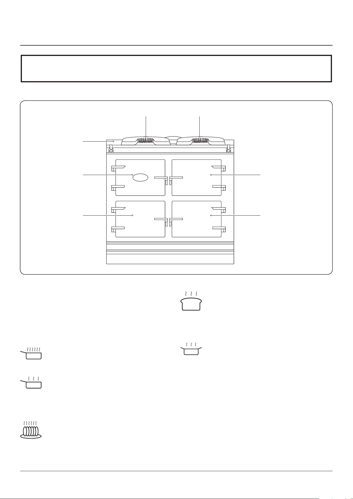
Simmering Plate
Roasting Oven
Boiling Plate
Top Plate
Control Panel
Slow Cook OvenBaking Oven
4. Overview
WARNING: ACCESSIBLE PARTS MAY BECOME HOT DURING USE. TO AVOID BURNS AND SCALDS CHILDREN
SHOULD BE KEPT AWAY.
AGA TC3
Fig. 4.1
DESN 517448
The AGA TC3 has the traditional cast iron ovens with
independently controlled hotplates.
Hotplates
The two hotplates are at dierent heats; the boiling plate
being the hottest of the two and the simmering plate is a
lower heat. Each plate is individually controlled.
Boiling Plate
The boiling plate is used for making toast, boiling a
kettle, stir-frying and cooking at a higher heat.
Simmering Plate
The simmering plate is for slower cooking, such as
sauces, simmering pans and can also be used to
Roasting Oven
cook on directly for toasted sandwiches, drop
scones, no-fat fried eggs and quesadillas.
The hottest oven for high temperature cooking;
pastries breads, roasting of meat, vegetables and
poultry, grilling at the top of the oven and frying on
the oor.
Baking Oven
Slow Cook Oven
A moderate oven for cooking cakes and biscuits,
baking sh, lasagne or shepherds pie, plus roasting
meat and poultry at a medium heat. Cooking sweet
and savoury together is no problem as the avours
do not mix.
Long, slow cooking in the Slow Cook Oven
develops avours and makes the toughest meat
tender. It’s large capacity means several pans can
be stacked here; soup, casserole, steamed rice,
steamed carrots and poached pears all cooking
simultaneously, without any danger of burning.
6
Page 11
5. Operating the AGA Total Control
Fig. 5.1
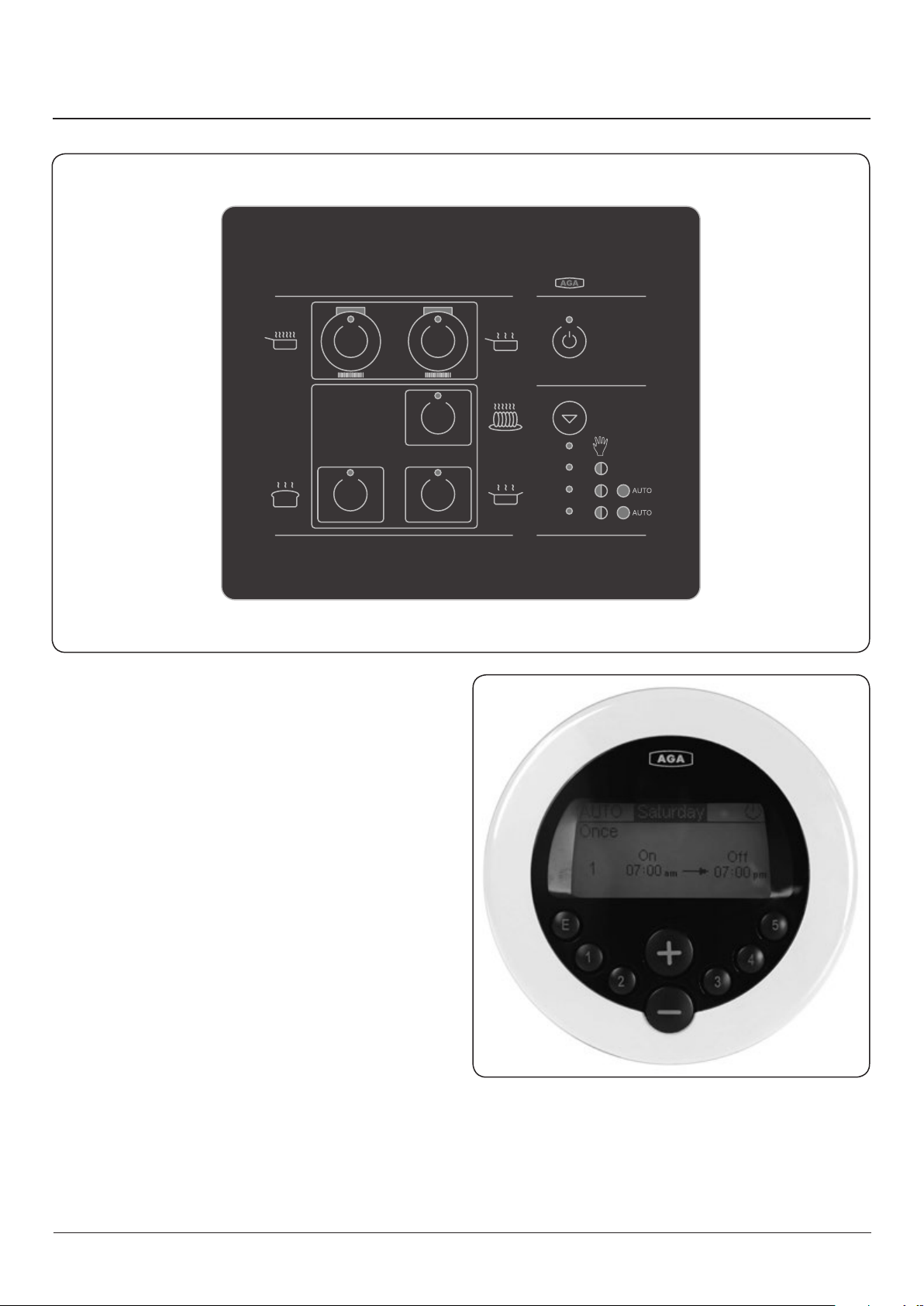
Control Panel Fig. 5.1
This is situated behind the top left hand door. The control
panel contains touch sensitive buttons with a green or
orange light (LED indicator) to indicate which zone is
activated. An audible beep will conrm selection.
Handset Fig. 5.2
Your AGA Total Control cooker also comes with a Handset
which can be used to program the ovens. It displays the time,
date and program events. The hotplates work on Manual only.
DESN 517464
Fig. 5.2
DESN 517465
7
Page 12
Getting started
When switching on the AGA cooker for the rst few times,
there are two things you may notice, neither of which should
cause concern.
1. A little smoke and some odour may be emitted when
rst switched on. This is normal and harmless (from
oven lagging and starch binder on the element
insulation) and will cease after a short period of use.
2. Condensation may occur on the top and front plate
whilst the AGA cooker is heating up, caused by the
internal insulation drying out. The condensation should
be wiped away as soon as possible to prevent staining
the enamel.
Your AGA Total Control has the external appearance of a
classic AGA heat storage enamelled cast iron cooker. However
its exibility is almost unbounded because in place of a single
heat source each cooking zone has its own electrically heated
cast iron element(s). The separation of cooking zones, allows
a choice of control. You are able to select only those zones
that you want, or need, to use.
The control panel is situated behind the top left hand door. It
contains touch sensitive buttons with a green or orange light
(LED indicator) to indicate which zone is activated. An audible
beep will conrm selection. There are eight buttons:
Standby/ON
Mode
Manual > Slumber > AUTO > AUTO/Slumber selection
Boil (Boiling plate)
ON/OFF
Simmer (Simmering plate)
ON/OFF
Roast (Roasting oven)
ON/OFF or selected for AUTO or AUTO/Slumber
Bake (Baking oven)
ON/OFF or selected for AUTO or AUTO/Slumber
Simmer (Slow cook oven)
ON/OFF or selected for AUTO or AUTO/Slumber
The appliance has 4 operating modes:
Mode Selection Button
Manual > Slumber > AUTO > AUTO/Slumber selection can
only be made when standby button is on.
Standby Button
This button must be on i.e. green to operate any part of your
AGA Total Control, or for any Timed events.
Manual simply select what you require
Each heat zone (an oven or a hotplate) can be turned on or
o as required, just press the appropriate button, a green
light will show when a specic zone is in operation.
The green indicator light of the selected zone (s) will ash
slowly indicating that the zone (s) is warming up. Once the
selected zone (s) is at temperature and ready to use the green
light will stop ashing. It is normal for the green light to ash
slowly during cooking, this indicates that the heat zone is
requesting power. While in Manual mode any zone selected
will remain on indenitely until switched o.
Slumber (ovens only)
In this mode, all three ovens are active, (the roasting and
baking oven are pre-set to approximately 248°F, the slow
cook oven is pre-set to approximately 212°F).
When selected, the orange indicator light of the ovens will
ash slowly, indicating that the ovens are warming up, when
‘Slumber’ temperature is reached the orange light will stop
ashing.
No individual oven can be ‘OFF’. However any oven can be
switched from ‘Slumber’ to full heat by one press of its button.
When pressed once, the selected oven goes to ‘full heat’, there
will be a ashing green light, when at temperature the light
will stop ashing.
Pressing an individual oven button once more returns that
oven back to ‘Slumber’.
AUTO (ovens only) - brings selected ovens up to full heat from
OFF
The ovens can be selected to operate once or twice each day.
Each operation is termed an ‘event’, the start and nish time is
chosen by you unless you use the pre-set time.
The handset will have been set up by the installer. It should
have the correct time of day set. Unless you have set your
own Auto program, it will include the pre-set time (1 Event
7am - 7pm).
See page 12 to set your own Auto program preferences.
1. Select ‘AUTO’ mode.
2. Select oven (s) for automatic operation, by pressing the
appropriate button (s).
3. The oven (s) selected is indicated by an orange light
(unless you have selected ‘AUTO’ during an ‘event’
period). During an ‘event’period the light will be green.
4. The oven light will ash green while the oven is heating.
When at temperature the green light will stop ashing.
8
Page 13

PLEASE NOTE:
• Don’t forget to include time for warm-up.
• Don’t forget if you have set the AUTO program and have
selected the AUTO mode, an oven or ovens must be
selected.
• The hotplates can only be operated manually.
• The last ‘AUTO’ oven selection is remembered and re-
called when ‘AUTO’ is next selected.
DO NOT OPERATE WITH THE APPLIANCE DOORS
OPEN
AUTO/Slumber (ovens only) - brings selected ovens up to full
heat from Slumber.
The ovens can be selected to operate once or twice each day.
Each operation is termed an ‘event’, the start and nish time is
chosen by you unless you use the pre-set time.
See page 12 to set your own Auto program preferences.
1. Select ‘AUTO/Slumber’.
2. Select oven (s) for automatic operation, by pressing the
appropriate buttons.
3. The oven (s) selected is indicated by an orange light
(unless you have selected ‘AUTO/Slumber’ during an
‘event’ period). During an ‘event’ period the light will be
green.
4. The oven (s) selected is indicated by an orange light, the
oven light will ash orange until ‘Slumber’ temperature
has been reached.
5. The oven light will ash green while the oven is heating
from ‘Slumber’ to full temperature during its Auto/
Slumber event period. When at full temperature the
green light will stop ashing.
PLEASE NOTE:-
• Don’t forget to include time for warm-up.
General Advice
Food SHOULD NOT be placed into any oven until it is up
to normal operating heat i.e. the green light of the selected
oven is solid and not ashing.
The oven doors should not be left open for long periods of
time during cooking and heating up.
Store the cold plain shelf outside the cooker. Use it cold in
the roasting oven to deect heat from the top of the oven,
creating a more moderate oven temperature underneath. It
can also be used as a baking sheet.
When an oven or hotplate is at temperature, and is then
loaded with food or cold pans/trays, the zone light may ash
as the oven and/or hotplate calls for extra heat.
Warm up times
When a zone is heating up it will be indicated by a ashing
green or orange light on the control panel. When a zone
has reached temperature a solid green or orange light will
indicate it has warmed up, AGA recommends that for full heat
to saturate the castings it is best to leave them for one hour
for the optimum cooking results.
Boiling Plate
The boiling plate takes approximately 11 minutes to reach
temperature from cold.
Simmering Plate
The simmering plate takes approximately 8 minutes to reach
temperature from cold.
Roasting Oven
The roasting oven takes approximately 35 minutes to reach
temperature from cold, and approximately 15 minutes to
reach temperature from ‘Slumber’.
Baking Oven
The baking oven takes approximately 22 minutes to reach
temperature from cold, and approximately 15 minutes to
reach temperature from ‘Slumber’.
• Don’t forget if you have set the AUTO/Slumber program
and have selected the AUTO/Slumber mode, an oven or
ovens must be selected.
• The hotplates can only be operated manually.
• All the selected ovens will remain at ‘Slumber’ between
‘events’.
• The last ‘AUTO/Slumber’ oven selection is remembered
and re-called when ‘AUTO’ is next selected.
DO NOT OPERATE WITH THE APPLIANCE DOORS
OPEN
AUTO and AUTO/Slumber
Changing between any of the four operating modes, will
cause the hotplates to switch OFF if in use - this is a built-in
safety factor. They can be switched back on after the mode
change if required.
Slow Cook Oven
The slow cook oven takes approximately 45 minutes to reach
temperature from cold.
PLEASE NOTE: For optimum cooking performance, after
the temperature has been reached, we recommend leaving
for another 30 minutes for the castings to become heat
saturated, particularly relevant if you are cooking a large meal
or baking.
PLEASE NOTE: The times are based on each zone being
operated individually. If a large combination of zones are
turned on simultaneously, it may slow down the individual
warm up times. If all zones are turned on at the same time it
will take approximately one hour for the whole appliance to
reach operating temperature.
These times are based on the cooker having a single
phase supply of 36 amps @ 240 V. For other power supply
congurations, these times may change.
9
Page 14
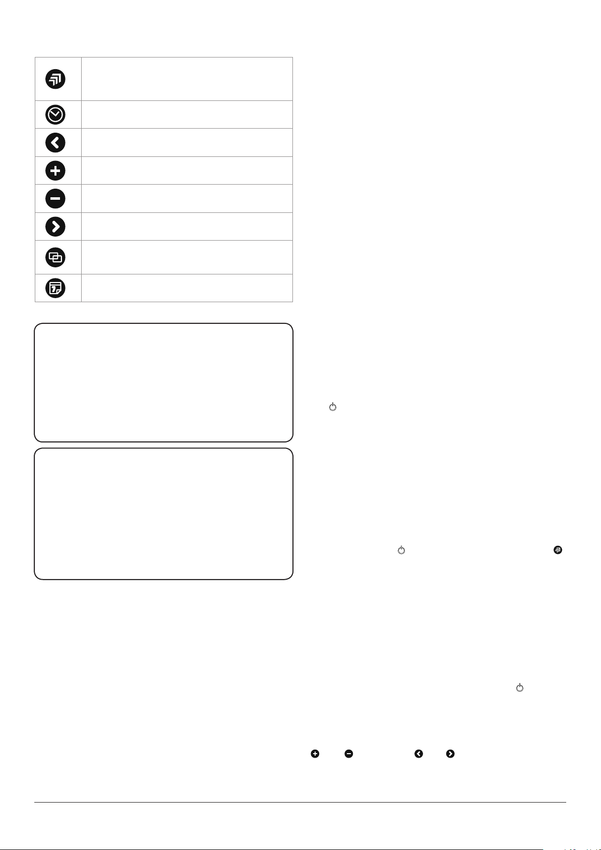
Communication or ‘Handshake’ button
Used initially to synchronise the handset to the AGA Total
Control. (On day of installation or in case of replacement
handset.)
Clock button
Opens and closes the date and time settings screen.
Left/Back button
Moves back and highlights the previous setting.
Plus button
Increases the highlighted setting.
Minus button
Decreases the highlighted setting.
Right/Forward button
Moves forward and highlights the next setting.
Copy button
Copies the time program from the current day to the
following day in the 7-day event calendar screen.
7-day event button
Opens and closes the 7-day event calendar screen.
Handset Fig. 5.2
The handset displays the time, date and events. Programming
is via eight push buttons. The information is displayed via a
back-lit LCD screen.
Screens
The handset has 3 main screens.
1. The Information Home screen (main menu)
2. The Date/Time screen
3. The Events Programming screen
The display will revert to ‘sleep’ mode after approximately 3
minutes. Simply press the required button to open up any
screen.
Handset Advice
Operating Distance
Table 5.1 Button Operations
USA
Model Number AGA TC3
FCC ID: A2M-AGA-TC3
FCC ID: A2M-AGA-TC3TEK
This device complies with part 15 of the FCC Rules. Operation is subject
to the following two conditions: (1) This device may not cause harmful
interference, and (2) this device must accept any interference received,
including interference that may cause undesired operation.
CANADA
Model Number AGA TC3
IC: 10181A-AGATC3TEK
Model Number AE4M280526
IC: 10181A-AGATC3
This device complies with Industry Canada licence-exempt RSS standard(s).
Operation is subject to the following two conditions: (1) this device may
not cause interference, and (2) this device must accept any interference,
including interference that may cause undesired operation of the device.
The handset will only operate in the same room as the
cooker and up to a maximum distance of 13 feet (4 metres)
from the appliance. If out of recommended operating range,
the handset may show ‘Standby’. If this happens move the
handset back to within the recommended distance and it
should correct itself, see below.
Handset to AGA Total Control Signal Check
The
symbol is shown when in the following situations:-
1. In Standby mode
2. If communications fail
3. There is a power cut
4. If the handset is out of range of the AGA Total Control
cooker
When transferring information from or to the controller
always operate the handset in front of the cooker, this gives
the strongest signal.
If the handset shows
, when the cooker is on, press the
button rmly for 1 second, this will activate the
communication link between the cooker and handset.
Communication/Handshake
For details on initial Communication/Handshake, see page
11.
Preview Mode
If the handset is out of range of the cooker or if the appliance
is switched o, Preview only mode is available. Changes
cannot be made to the programmed events. The
symbol
is displayed in the screen and the message ‘Preview only’ is
displayed briey when the events program screen is rst
entered.
When in Preview Mode you can review the days by using the
and buttons. The and buttons become inactive
and you cannot make any changes.
10
Page 15
Handset Failure
In the unlikely event of handset failure, the appliance would
still be operational with the last selected program. The cooker
can also be changed to Manual mode from one of the auto
modes using the mode button on the control panel. If the
handset is damaged or lost, a replacement can be obtained
from AGA and re-programmed to suit your appliance.
DO NOT PLACE THE HANDSET ON ANY HOT
SURFACES.
Fig. 5.3
Communication/Handshake
This process will be required on the original installation of the
AGA Total Control. If the handset is replaced for any reason
the new handset will need to be synchronised.
• You will also need to set the time and date.
• You will also be given the option to set your own Auto
program preferences.
1. Handshake can be activated 30 seconds after main
power has been applied to the cooker. The Standby
button on the touch panel must be ‘ON’. It must then be
completed within 2 minutes, otherwise you will need to
repeat the process Fig. 5.3.
2. Press and hold button on the handset for 10 seconds
to open the communicate/synchronise screen. The
following screen message then appears Fig. 5.4.
3. Simultaneously press the and buttons, the serial
number will be ‘found’ by the handset. The following
screen message then appears briey Fig. 5.5.
4. Use the and buttons to choose the language you
want the handset text to be in, then press to conrm
the language choice required. Once time and date has
been set the Auto/Event program screen will appear.
Press
to synchronise
Serial Number
and
found
DESN 516300
Fig. 5.4
Fig. 5.5
5. Set the correct time and date page 12
6. You have the option to set your own Auto program,
refer to page 12. If you wish to leave until later, then
press it will remain at the pre-set times: 1 Event 7am
- 7pm (7 days).
Notes
• symbol appears in the top right hand corner of the
screen, if the handset is out of range with the cooker or
the communication/handshake process has not been
completed. When communication is OK then symbol
is displayed.
• The button can be used to force communication
between the cooker and the handset. This function is
active once successful initial communication has been
made, and the handset is in range.
11
Page 16

Fig. 5.6
Date and Time Setting
Press and hold Clock button until the screen is displayed
Fig. 5.6. In this screen the time, date, month and year can be
altered/set.
Press the and buttons to
Press the and buttons to
alter the highlighted time, date,
month and year settings.
DESN 516301
cycle between the time,
date, month and year.
Fig. 5.7
1.
2.
DESN 516302
B.
3.
5.
A. Stand-by icon will appear if in Preview Mode.
B. Setting:
• ‘Twice’ will be shown if two events are set.
• ‘Once’ will be shown if one event is set.
• ‘No’ will be shown if no events are set.
Press
button at any stage to save the settings and exit the
DATE/TIME screen.
‘Message sent OK’ will appear on the screen when the
handset is in range of the cooker.
‘Changes stored on handset only’ will appear on the screen,
when the controller handset is out of range of the cooker.
Notes
• Even if no changes are made to the time, date, month
and year settings, a press of the clock button is still
A.
required, to return to the Home screen.
• The day cannot be changed as the handset
automatically knows this information, when the date
and year is set.
4.
6.
• The Home screen will automatically appear after the
replacement of new batteries.
Auto/Events program screen
This screen Fig. 5.7 is opened by pressing the 7-day event
button .
In this screen, the number of events and the start and end
time of events can be set. Each day can have a dierent
number of events, and start and end times, or all seven days
can be the same.
There are pre-set times already programmed, to change to
your desired settings follow these instructions. Pre-set times
are 1 event 7am - 7pm (7 days).
What you can do
1. The current day is shown on the display, this can be
changed to the day that you wish to edit by pressing the
and buttons.
2. This shows the number of events in that day. This can be
changed from no, once or twice by pressing the and
buttons.
3. This shows the start time of the rst event. This can be
changed by pressing the and buttons.
4. This shows the end time of the rst event. This can be
changed by pressing the and buttons.
5. This shows the start time of the second event. This can
be changed by pressing the and buttons.
6. This shows the end time of the second event. This can
be changed by pressing the and buttons.
12
Page 17

How you do it
1. Press the or buttons to navigate through the
settings on the screen. When a setting is selected
it will be highlighted by a dark box. Pressing the and
buttons. will change the information in this
highlighted box.
A.
D. D.
Fig. 5.8
B. C.
2. Press to copy program settings to next day.
3. If you have made changes and wish to exit this screen,
press the button. A ‘Save Changes’ - Yes or No?
message will appear on the screen.
4. Pressing the and buttons will highlight Yes or No.
Press the button again to conrm your choice.
REMEMBER: After setting the Auto event that an oven
selection must be chosen on the touch panel if you wish
to activate the program you have just entered.
Notes
Even if no changes are made a press of the
button is still
required, to return to the Home screen.
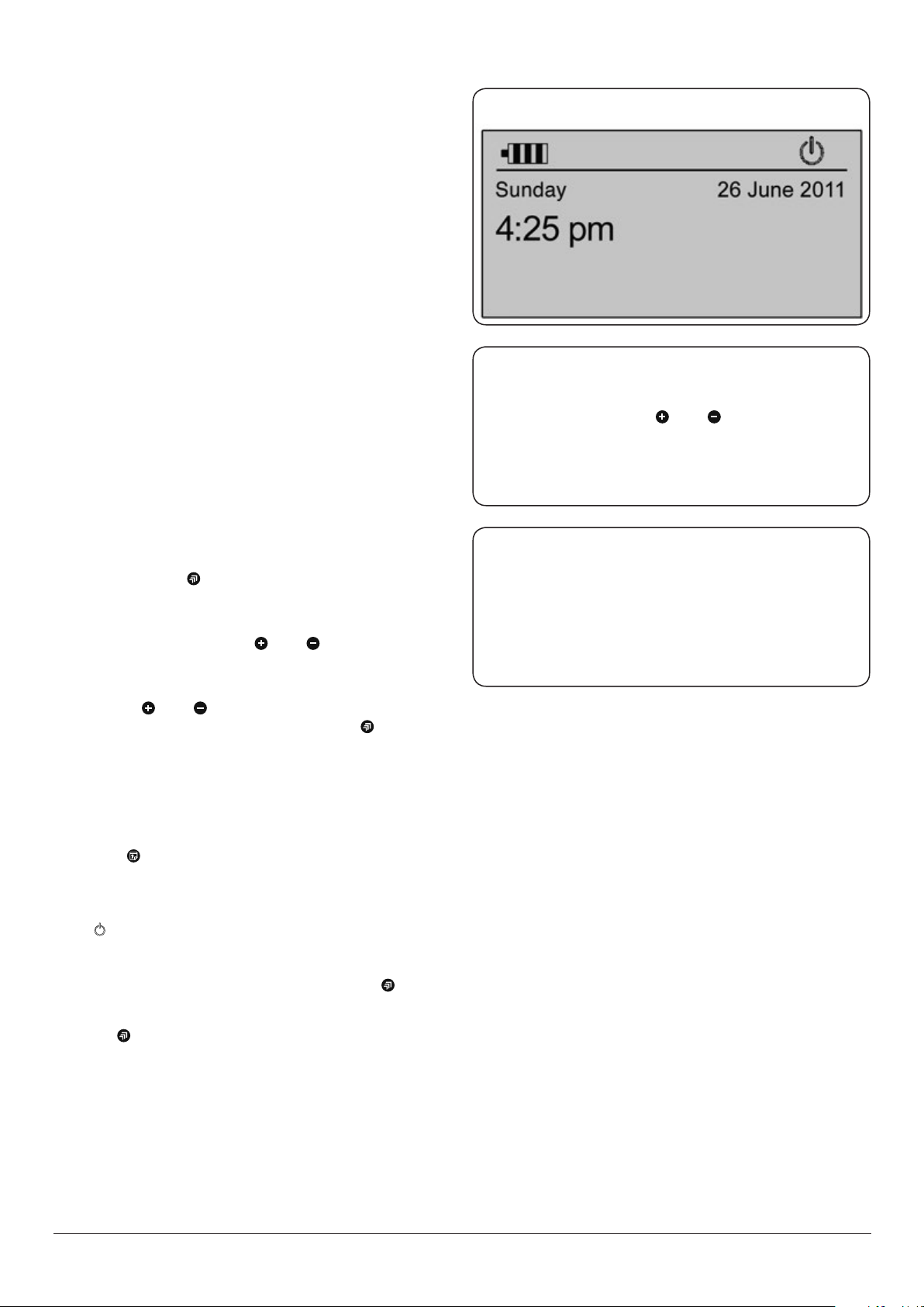
Information (Home) Screen
This is the main screen Fig. 5.8, where information such as
time, date, battery life and connectivity is displayed. If you
have programmed either of the ‘AUTO’ modes and they are
currently in progress, the next change of event will also be
displayed. The information below explains this in more detail.
Press any button on the handset to open this screen, from
‘Sleep’ mode.
D.
E. F.
DESN 516303
A. Symbol indicating the battery life.
B. If there is no communication between the AGA Total
Control and the handset because: the cooker is not
powered, in standby or the handset is out of range from
the cooker. The symbol is displayed.
C. Communication/Handshake symbol indicates
communication between the cooker and handset is OK.
D. Symbols indicating the current time and day.
E. Warning triangle and error code is displayed if an error
occurs.
F. If either AUTO or AUTO/Slumber mode is active the next
event change will be displayed for that day with the
relevant symbols to show start and end times.
NOTE: If standby icon is shown then event indicator will not
be displayed.
Change of Event Symbols
• > AUTO event ON (before AUTO event)
• > AUTO event OFF (during AUTO event)
• > AUTO/Slumber event ON (before AUTO/
Slumber event)
• > AUTO/Slumber event OFF (during AUTO/
Slumber event)
13
Page 18

Fig. 5.9
Power Outages under 10 minutes
When the power is restored, the AGA Total Control will
resume normal operation as was set prior to the power
interruption.
Power Outages over 10 minutes
Most functions will have turned OFF.
• ‘Manual’ mode - all zones OFF.
• ‘Slumber’ mode - hotplates OFF, Slumber ON
DESN 517480
Fig. 5.10
DESN 517481
Fig. 5.11
• ‘AUTO’ mode - hotplates OFF, ovens continue with the
set programme.
• ‘AUTO/Slumber’ - hotplates OFF, ovens continue with
the set programme.
A ‘Power Outage’ message may appear on the handset screen,
conrm by pressing any button on the handset. Therefore the
cooker may not be at temperature when expected.
Automatic Update of Time
In the event of power cuts the handset will automatically
update the controls within the cooker to the correct time
on restoration of power. This is provided that the following
criteria are met:
1. The handset is sited within range of the cooker
2. The handset has good batteries
3. The handset contains the correct time itself
Batteries
The handset is tted with four ‘AAA’ batteries, which are
packed separately. Your installer will insert them when your
AGA Total Control cooker is installed. When replacing the
batteries, follow these instructions inconjunction with the
diagrams.
DESN 517482
Remove the handset from its backplate, then remove the
battery cover plate from the rear of the handset (Fig. 5.9).
Carefully lever out the batteries commencing with the
bottom one rst pushing and pulling out on the positive (+)
end only (Fig. 5.10). Repeat this procedure to remove the
other batteries.
Always use long life batteries for replacements - rechargeable
batteries are not recommended.
Replace the batteries commencing with the bottom one
working to the top (Fig. 5.11).
Battery life will depend on usage. Replace the batteries when
the battery symbol on the handset is down to one bar.
Care and Cleaning
The handset should be wiped clean using a soft clean cloth.
Do not use abrasive cleaning products or submerge the
handset in water.
No changes or modications should be made to the
handset. Changes or modications not approved by
AGA could void the users authority to operate the
handset.
14
Page 19

6. AGA Accessories
To get the very best performance from your range we
recommend AGA saucepans with the thick tri-core bases and
stacking lids so that the maximum use of oven space is made
and an AGA kettle for boiling water. AGA Accessories can be
viewed at your AGA Specialist or online at www.agacookshop.
co.uk
Getting to know your AGA
If you have not already seen a demonstration, ask your AGA
Specialist for details. A demonstration will show you how
to get the best from your new AGA and will give you hints
and tips. You will also see a selection of AGA utensils and
accessories being used.
Large Size Roasting Tin with Grill Rack (Fig. 6.1)
This is designed to slide onto the oven runners without the
need for it to sit on an oven grid shelf. The roasting tin can be
used with the grill rack, in its high position, for grilling at the
top of the roasting oven. It can be used for roasting meat, or
poultry with or without the grill rack. Large quantities of roast
potatoes can be cooked in this tin. The roasting tin can also
be employed for making large traybakes or cakes. The grill
rack is useful on its own as a cake cooling rack. Can be used in
any oven but not recommended for hotplate use.
Fig. 6.1
Fig. 6.2
Half Size Roasting Tin and Grill Rack (Fig. 6.2)
This tin can be slid onto the oven runners width-ways or can
sit on an oven grid shelf. The half size roasting tin can be
used with the grill rack, in its high position, for grilling at the
top of the roasting oven. It can be used for roasting smaller
joints of meat, or poultry with or without the grill rack. Roast
potatoes can be cooked in this tin. The roasting tin can also
be employed for making traybakes or cakes. The grill rack is
useful on its own as a cake cooling rack. Can be used in any
oven but not recommended for hotplate use.
1 Floor Grid (Fig. 6.3)
This grid is used on the oor of the ovens, in particular the
roasting and simmering ovens to protect food needing over
30 minutes cooking from the intensity of the heat from the
base element.
3 Oven Grid Shelves (Fig. 6.4)
These are for inserting in each oven to provide a surface for
dishes and tins which do not t direct onto the oven runners.
They can be used in any oven, as required. See page 20 on
how to locate the oven shelves correctly.
Fig. 6.3
Fig. 6.4
15
Page 20

Fig. 6.5
Fig. 6.6
1 Cold Plain Shelf (Fig. 6.5)
This has two uses one as large baking sheet for scones,
biscuits, pastry items and meringues and the other use as a
heat deector to cut o the top heat if food is overbrowning
before it is cooked through.
DO NOT STORE IN THE OVENS WHEN NOT IN USE.
Roasting Oven Perforated Bae (Fig. 6.6)
A roasting oven perforated bae is positioned in the top of
the roasting oven, in order to optimise cooking performance.
For best results, please ensure it is in place at all times,
while the oven is in operation, including when grilling. The
Installation Engineer will t this in place. This can also be
removed for cleaning.
Toaster (Fig. 6.7)
This is for toasting bread on the boiling plate. AGA toast is
renowned for its excellence, crisp on the outside and soft in
the centre. Take thick slices of bread and place in the AGA
toaster - if the bread is very moist or very fresh, heat the
toaster beforehand to prevent sticking - lift the boiling plate
insulated cover and place the toaster direct onto the plate
with the handle at an angle from the handle of the cover.
Fig. 6.7
Fig. 6.8
Close the cover and wait for the bread to toast one side this will take 1-2 minutes dependent upon the variety of
bread - open the cover and turn the toaster over and repeat
the process to toast the other side. The toaster can also be
used for heating pitta bread, toasting teacakes and as a cake
cooling rack.
Wire Brush (Fig. 6.8)
This is for cleaning the raw cast iron surfaces, keeping them
clear of crumbs and burnt on debris – which would otherwise
aect the boiling performance of pans and the kettle. Use
on the hotplates and the ovens. Take care not to touch the
enamel surfaces as the wire brush will scratch the nish.
Getting to know your AGA
If you have not already seen a demonstration, ask your AGA
Specialist for details. A demonstration will show you how
to get the best from your new AGA and will give you hints
and tips. You will also see a selection of AGA utensils and
accessories being used.
16
Page 21

Fitting the Oven Shelves
Fig. 6.1
Fig. 6.2
DESN 512403
Removing the Oven Shelves
Fig. 6.3
DESN 512404
Fig. 6.4
DESN 512405
DESN 512406
17
Page 22

7. The Ovens
Your AGA Total Control has three ovens, each of which is preset at a dierent heat, just like the classic AGA heat storage
cooker. They are named as:
• The Roasting Oven for high temperature cooking
• The Baking Oven for moderate temperature cooking
• The Slow Cook Oven for long slow low temperature
cooking
DO NOT OPERATE THIS APPLIANCE WITH THE DOORS
OPEN, SINCE THIS CAN CAUSE A LOCK-OUT.
Each oven has the same capacity, (able to t a 28lb (13kg)
turkey) and the classic AGA heat-storage cooker techniques
can be used such as stacking of saucepans in the slow cook
oven. This enables the steaming of root vegetables, rice,
steamed pudding, casserole, poaching fruit all in the one
oven leaving the hotplates free and reducing steam and
cooking smells in the kitchen.
You can have one, two or all three ovens on at their pre-set
heat or the roasting and baking ovens can also be at ‘Slumber’
mode, (the slow cook oven is always at the same heat).
The ovens are made from cast iron, which cooks by a radiant
heat and this is the secret of the cooking excellence for which
the AGA cooker is renowned. An indirect radiant heat does
not dry food out, so it retains its natural moisture and avor.
Slumber Mode
In Slumber mode, all three ovens operate like a slow cook
oven.
The slow cook oven is always in Slumber, whereas the
roasting and baking oven can be set on Slumber mode for
either cooking at a low heat, or to generate gentle warmth
into the kitchen, or in readiness for turning up to their normal
pre-set heat.
Cooking at Slumber in the roasting oven or baking ovens
gives the best results for making large rich fruit cakes and
meringues as they benet from the gentle heat of top and
base elements to ensure thorough cooking. Other foods
which benet from cooking at Slumber in these are ovens
are steamed and Christmas Puddings and slow cooking
large pieces/cuts of meat - start the cooking process before
placing the oven on Slumber.
Recipes in the separate recipe book cooked on slumber
are:
62 | Pears with Cardamom
68 | Steamed Banana pudding drizzled in Butterscotch Sauce
88 | Fruity Celebration Cake
18
Page 23

Simmering Plate
Roasting Oven
Boiling Plate
Top Plate
Control Panel
Slow Cook OvenBaking Oven
Fig. 7.1
The Roasting Oven
The roasting oven is indirectly heated by two elements,
one in the base of the oven and the other in the roof. These
elements heat the air and the cast iron within to provide
cooking results consistent with the classic AGA heat-storage
cooker, with the exibility of being able to turn it to Slumber
or O when not required.
The roasting oven can be used for ‘broiling’ at the top and
‘shallow frying’ on the oven oor.
• When cooking on the bottom of the roasting oven for
long periods of time (more than 30 minutes), place the
floor grid on the bottom of the oven before putting the
food into the oven, this lifts the food away from the base
element to ensure best cooking results are achieved.
A note when cooking on the bottom of the roasting oven.
• Please leave 1 hour before cooking directly on the
bottom of the oven, this is to ensure maximum
temperature stabilisation of the base element.
• You can cook directly on the bottom of the roasting
oven for short periods of time e.g. pizza, quiche, or
foods that take 30 minutes or less.
DESN 517448
Fig. 7.2
DESN 517483
NOTE: The roasting oven perforated bae should be
positioned in the top of the roasting oven in order to
optimise cooking performance. It must be in place at all
times, while the cooker is in operation, including when
grilling. Refer to Fig. 7.2 for tment of roasting oven
perforated bae.
19
Page 24

The roasting oven can used for ‘grilling’ at the top and ‘shallow
frying’ on the oven oor.
The roasting oven is zoned in heat, meaning it is slightly
hotter towards the top than the centre and the oven grid
shelf set on the oven oor is slightly less hot than the centre.
The beauty of the roasting oven is that any fat splashes
are burnt o when the oven is at full heat, just brush out
occasionally to get rid of carbon deposits.
The roasting oven is excellent for bread and pastries. Quiches
in ceramic or pies in Pyrex dishes need not be baked blind
as when they are placed on the oor grid on the base of the
oven, the pastry cooks from underneath and the lling will
set and brown from the all-round heat. As you are aware
metal an tins conduct heat quicker than ceramic so may
need less cooking time.
The specially designed roasting tins and bakeware slide
directly onto the runners, so almost every available square
centimetre of space can be used. Food can be protected by
the use of the cold plain shelf or shielded by means of the
large roasting tin, which means that you can cook food that
requires dierent temperatures at the same time. If food is
browning too quickly and you do not want to move it to
another oven just slide the cold plain shelf over the food to
reduce the top heat.
For recipe ideas, see separate recipe book.
The Baking Oven
The baking oven is indirectly heated by two elements, one
in the base of the oven and the other in the roof. These
elements heat the air and the cast iron within to provide
cooking results consistent with classic AGA heat-storage
cookers, with the exibility of being able to turn it to Slumber
or O when not required.
This oven is set at a moderate heat, so is ideal for cakes,
biscuits; also anything that requires medium heat cooking
such as sh pie, lasagne, soués, crumble and roulades. Meat
and poultry can be cooked here indeed most things that can
be cooked in the roasting oven can be cooked in the baking
oven but for a longer time.
For the best results when cooking cakes do allow an hour
heat up time. Cook cakes together on one shelf if two shelves
are used interchange the food to achieve even coloration, as
you would with any oven which is zoned in heat.
As with the roasting oven the specially designed roasting tins
and bakeware slide directly onto the runners, so almost every
available square centimetre of space can be used. Food can
be protected by the use of the cold plain shelf or shielded by
means of the large roasting tin, which means that you can
cook food that requires dierent temperatures at the same
time.
If food is browning too quickly and you do not want to move
it to another oven just slide the cold plain shelf over the food
to reduce the top heat.
Baking Oven at Slumber
When the baking oven is set at Slumber it can be used to
cook rich fruit cakes or slow cook roasts, casseroles and
curries.
With the exception of meringues and rich fruit cakes, food
that is to be slow cooked should be brought up to heat
before placing in an oven at Slumber. The light will ash
orange when heating up to
Slumber, then go solid orange when up to temperature.
For recipe ideas, see separate recipe book.
20
Page 25

Slow Cook Oven
The slow cook oven is indirectly heated by one element in the
base of the oven.
This element heats the air and the cast iron within to provide
cooking results consistent with the traditional slow cook oven
of the classic AGA heat-storage cooker, with the exibility of
being able to turn it to O when not required. The slow cook
oven is always at a simmer or Slumber mode ideal for long
slow cooking.
The oor grid is used here to protect items placed on the
bottom of the oven such as vegetables for steaming, keeping
sauces warm or casseroles cooked for a long time. Always
ensure this is in place, before putting food into the oven.
The Slow Cook Oven can be described as a continuation
oven, it continues to cook food that has been brought up to
heat elsewhere on the range with the exception of meringues
which are dried out rather than ‘cooked’. Therefore the
following recipes call for heating the food on the hotplates or
in the roasting oven before placing in the slow cook oven.
For recipe ideas, see separate recipe book.
User Guidance
Fig. 7.3
DESN 516321
• Allow the oven to heat up fully, the longer the oven is
on the better, since this helps reduce the amount of
moisture created during slow cooking.
• To get the very best performance, we recommend to
use AGA cookware with thick bases and stacking lids.
• Do not place dishes directly on to the oven base. Always
place onto either a shelf or the floor grid.
• Cuts of meat and poultry should be brought up to heat
ideally in the Roasting oven for 30 - 45 minutes, then
transfer to the Slow Cook oven.
• This method is unsuitable for stuffed meat and poultry.
• Make sure that pork and poultry reach an internal
temperature of at least 167°F.
• Always bring soups, casseroles and liquids to the boil on
the hotplate before putting in the oven.
• Always thaw frozen food completely before cooking.
• Root vegetables will cook better if cut into small pieces.
• Adjust seasonings and thickenings at the end of the
cooking time.
• Many dried beans for example, dried red kidney beans
must be boiled for a minimum of 10 minutes, after
soaking, and before inclusion in any dish.
PLEASE NOTE: DO NOT store anything in the Slow Cook
Oven and
cold plain shelf until the oven has reached its operating
temperature (Fig. 7.3). Failure to do this may cause the safety
function to lock the appliance in the OFF position. It is also
advisable when using large cookware in the Slow Cook Oven
to push it to the back of the oven.
DO NOT use any large cookware such as the
21
Page 26

Using the zones of the AGA Total
Control
The dierent zones of the AGA Total Control cooker are
described in the following pages individually. Recipe
suggestions are given for each area or zone with alternative
cooking methods - the choice is yours whichever is most
convenient to you. For instance you may prefer to use just
the hotplates for a quick dinner in the week or there can be
a choice of an oven alternative when you have the ovens
on during the colder weather or at weekends, when you are
doing more cooking.
The classic AGA heat storage cooker is famous for the gentle
warmth it emits, with the AGA Total Control you will get
warmth only when the cooker is on or warmth to a lesser
degree when only parts of it are on.
The whole hotplate area can be used for cooking and several
pans can be accomodated on a single plate at any one time.
The hotplates are set very slightly above the top plate to
avoid accidental scratching if the pans are pulled to one side.
DO NOT drag the utensils from one plate to another as the
enamel will suer!
The stainless steel insulated covers are brought down over
the hotplates when they are not in use. When the hotplates
are ‘on’ the insulated covers will be warm. We strongly advise
not to put anything such as kettles, saucepans or baking tins
directly onto the insulated covers because they will show any
scratches - invest in a pair of chef’s pads to protect the surface
if the covers are to be used as resting places!
Keep the hotplates clear of any burnt on food or crumbs
by brushing with the wire brush, supplied with your AGA.
Cleaning details can be found on page 24.
The Plates
Top Plate
The top plate is the enamelled surface surrounding the
hotplates. It will become warm when the AGA Total Control
hotplates are in use. Although it is not a cooking surface you
can use the warmth for a number of useful activities, which
more often than not save times and washing-up! These
include warming honey or syrup in the jar, or melting butter
or chocolate in a basin - so saving on melting over a saucepan
- but do please put the basin on a cork mat or folded piece
of kitchen towel to avoid scratching the enamel. Although it
is durable and hard-wearing surface vitreous enamel is glass
and will show scratch marks!
The top plate when warm can also be used to rest a cup of
coee or tea or dry o awkwardly shaped tins, peelers or food
mixer and processor parts.
Hotplates
The hotplates are operated manually, make sure the standby
button is on then just press the touch control panel of the
hotplate you need and a ashing green light will appear,
when the hotplate reaches its full preset heat it will become
solid green.
The boiling plate is on the left hand side and the simmering
plate is on the right hand side of the AGA Total Control. The
boiling plate is the hottest with the simmering plate being
the cooler of the two. They both have electric elements
embedded into the cast iron which heat up in approximately
11 and 8 minutes respectively. The hotplates can be used
completely independently from the ovens.
Boiling Plate
The hottest hotplate, the boiling plate is used for boiling,
griddling, stir-frying, making toast - indeed anything that
requires a high heat. Green vegetables keep their colour
when boiled quickly here, or use a steamer over the saucepan
to cook more than one vegetable at once.
When stir-frying or cooking anything that is inclined to splash
we would recommend using an AGA Splash Shield which will
protect the insulated cover from splatter, making cleaning
a doddle! Just wash the Splash Shield in hot soapy water or
place in a dishwasher between two dinner plates.
Please be advised the boiling plate is too hot to cook food on
directly.
For recipes ideas , see separate recipe book.
Simmering Plate
The simmering plate is the cooler of the two hotplates and so
is used for recipes that require a lower heat such as making
sauces, scrambling eggs, heating milk, slow frying, simmering
soups and root vegetables. In addition, it can be used to
cook on directly as a form of griddle - invaluable for toasted
sandwiches, quesadillas, soups, drop scones, searing scallops
and even a non-fat fried egg! Slow cooked toast can be made
on the simmering plate, no need here to use the AGA toaster.
The same size as the boiling plate, the simmering plate is also
machined at to give the best all-over contact with the AGA
saucepans, grill pan, frying pan and kettle.
Cleaning details can be found on page 24.
For recipes ideas, see separate recipe book.
This means the AGA Total Control diers from the traditional
AGA heat storage range in that they can be used for the
entire cooking time of appropriate dishes because the
design keeps the hotplates at a constant heat, whereas the
traditional AGA range continues to cook on a falling heat
so for these we recommend starting on the hotplates then
transferring to the ovens, this can be done with the AGA Total
Control but is not necessary. For instance, if making a pasta
dish with sauce on the AGA Total Control, it can all be done
on the hotplates.
22
Page 27

This unit is heavy, proper equipment and adequate manpower must be used to remove the oven doors.
Fitting the Doors
CAUTION:
Fig. 7.1
Fig. 7.2
DESN 517491
Removing the Doors
Fig. 7.3
DESN 517489
Fig. 7.4
DESN 517489
DESN 517490
23
Page 28

8. Cleaning & Caring for your Range
WARNING: ACCESSIBLE PARTS MAY BECOME HOT DURING USE. TO AVOID BURNS AND SCALDS CHILDREN
SHOULD BE KEPT AWAY.
REMEMBER: be careful of the hot appliance.
For most cleaning it is best when the appliance is
turned o.
DO NOT use a steam cleaner to clean this range.
DO NOT use abrasive pads, caustic cleaners, oven
cleaners or metal scrapers to clean the surfaces of
the enamel.
The touch control panel may be cleaned with a damp
cloth and warm soapy water.
IMPORTANT: AGA recommend Vitreous Enamel
Association approved cleaners for cleaning the
vitreous enamelled surfaces of this product
obtainable from your AGA Retailer.
When cleaning use as little water as possible.
DO NOT immerse the doors in water as they are
packed with insulating material, which will be
damaged by excessive moisture.
DO NOT put oven doors or resting plates in a
dishwasher.
Top Plate and Front Plate
The easiest way to clean the AGA top plate and front
plate is to mop up spills as they happen.
Baked on food is more dicult to clean but can
usually be removed with proprietary vitreous
enamel cleaners or mild cream cleaners using a
cloth, or if necessary, a nylon scouring pad.
Cast iron ovens and hotplates
Ovens - are made from cast iron and keep themselves clean.
They are very durable, but will rust if surface moisture is left
on them. Remember to always switch the ovens on, to dry
them out after cleaning.
Heating up the ovens periodically will help burn o any
cooking deposits to aid cleaning within the ovens.
To season the ovens, a light vegetable spray oil (corn oil is
best) is recommended. Any stubborn stains can be removed
with the wire brush supplied.
Hotplates - is made from cast iron, and is easy to care for.
Regular maintenance will ensure long-life. They will rust if
surface moisture is left on them
Should the hotplates become soiled, use a sponge, cloth,
scouring pad or wire brush to remove burnt-on spills.
Rinse o detergents or cleaning agents thoroughly.
Remember to switch on the hotplate for a few minutes to dry
it after cleaning. Every now and then, apply a thin coating of
vegetable oil (corn oil is best) when the hotplate is cold.
Lids and oven door/lids linings
The top of the insulated cover (lid) - this is chrome or
stainless steel and can be kept clean by wiping over with a
damp cloth and polished up - the AGA E-cloths are excellent
for this purpose as they are lint-free and eco-friendly. AGA
stainless steel and chrome cleaner are recommended to
keep the insulated cover clean and shining. These can be
purchased from your local AGA Specialist.
If milk or fruit juice, or anything containing acid is
spilt on the enamel, wipe o immediately.
Clean o any condensation streaks on the front
plate, around the oven doors or any vitreous enamel
maybe permanently discoloured.
All that is usually needed to keep the vitreous
enamelled surfaces of your range bright and clean
is a daily rub over with a damp, soapy cloth followed
immediately with a clean, dry cloth to avoid streaks.
Remember the top plate and the polished covers will
scratch if pans or utensils are dragged across them.
To keep the vitreous enamel surfaces of the range bright
and clean, a daily rub over with a damp soapy cloth followed
immediately with a clean, dry cloth to avoid streaks is all that
is required. AGA E-cloths are excellent for this, obtainable
from your AGA Retailer.
Lining of the insulated cover (lid interior) - the use of an
AGA splash shield is recommended to keep the lining free of
fat splashes, obtainable obtainable from your AGA Retailer.
If the lining is marked it is best cleaned when the hotplate is
cold. It can be cleaned with hot soapy water and/or a cream
cleanser. If badly marked then a soap impregnated pad can
be used - this should be used in a circular motion.
The rst few times a soap impregnated pad is used you will
see the circular marks, these will become reduced and the
surface of the lining becomes shinier each time when used.
Do not use excessive water and make sure the lining is dry
before closing the cover.
Oven door linings - the linings can be cleaned with hot
soapy water, a cream cleanser or soap impregnated pad. To
deep clean the lining place a towel on the work surface and
carefully lift o the oven door (doors are heavy) and place it
enamel side down on the towel padding. Clean with a soap
impregnated pad to remove stubborn marks. Dry o before
replacing on their hinges.
24
Page 29

WARNING: ACCESSIBLE PARTS MAY BECOME HOT DURING USE. TO AVOID BURNS AND SCALDS CHILDREN
SHOULD BE KEPT AWAY.
Roasting Pans
The enamelled roasting pans supplied with the AGA Total
Control should be cleaned in hot soapy water, soaking if
necessary. A nylon scouring pad can also be used. They may
also be cleaned in the dishwasher, but with constant use, the
enamelled nish will become dull in appearance.
DO NOT use caustic cleaners or oven cleaners.
PLEASE NOTE: Cleaners used for Vitreous Enamel are
often unsuitable for use on: chrome and stainless steel
components, including the insulating covers, hand-rails and
their brackets.
25
Page 30

9. Troubleshooting
ERROR CODES
In the unlikely event an error occurs with your AGA Total
Control cooker, error codes may be displayed on your
handset, for example:
133
Please provide AGA Service with this information. It will assist
the service engineer with diagnosing your fault.
26
Page 31

10. Installation Instructions
CAUTION: THIS UNIT IS HEAVY, PROPER EQUIPMENT AND ADEQUATE MANPOWER MUST BE USED IN MOVING THE
RANGE TO AVOID DAMAGE TO THE UNIT OR THE FLOOR.
REMEMBER, when replacing a part on this appliance, use only spare parts that you can be assured conform to the safety and
performance specication that we require.
DO NOT use reconditioned or copy parts that have not been clearly authorised by AGA.
PLEASE READ THESE INSTRUCTIONS BEFORE USING THIS APPLIANCE
AND KEEP IN A SAFE PLACE FOR FUTURE REFERENCE.
27
Page 32

11. Installation Introduction
Health and Safety
Consumer Protection
As responsible manufacturers we take care to make sure
that our products are designed and constructed to meet the
required safety standards when properly installed and used.
IMPORTANT: Please read the accompanying
warranty.
Any alteration that is not approved by AGA could invalidate
the approval of the appliance, operation of the warranty and
could also aect your statutory rights.
In the interests of safety and eective use, please read the
following before using your new AGA appliance.
Installation Requirements
THIS APPLIANCE MUST ONLY BE INSTALLED BY PERSONS
THAT ARE CERTIFIED TO LOCAL REGULATIONS.
NOTE: This installation instruction should be left with the
appliance and the owner to retain for future use.
Before installation of an AGA can be made, the site is
inspected for suitability by an authorized AGA distributor and
corrected where necessary to conform with local or regional
electrical codes.
In your own interest and that of safety to comply with the
law, all appliances should be installed by an authorized AGA
distributor in accordance with the relevant regulations.
Delivery Requirements
• The AGA TC3 arrives on 1 pallet
There must be access to the kitchen to manipulate a foot
print of 39 ⁄” (1005mm) x 29 ⁄” (740mm). A wooden
template (skate with castor wheels) of dimensions 39 ⁄”
(1005mm) x 29 ⁄” 740mm could be used to check if the AGA
Total Control fully built appliance is able to t through the
property grounds and doors into its installation position in
the kitchen. It must also be considered that the height of the
appliance is 37 ⁄” (960mm) o pallet and 43 ⁄” (1100mm)
on the pallet, so high level obstacles/restrictions must not be
overlooked.
If this skate/template can be manipulated through the
property grounds and doors into position, then the AGA
can be installed as intended with no re-work.
USA
Model Number AGA TC3
FCC ID: A2M-AGA-TC3
FCC ID: A2M-AGA-TC3TEK
This device complies with part 15 of the FCC Rules. Operation is subject
to the following two conditions: (1) This device may not cause harmful
interference, and (2) this device must accept any interference received,
including interference that may cause undesired operation.
CANADA
Model Number AGA TC3
IC: 10181A-AGATC3TEK
Model Number AE4M280526
IC: 10181A-AGATC3
This device complies with Industry Canada licence-exempt RSS standard(s).
Operation is subject to the following two conditions: (1) this device may
not cause interference, and (2) this device must accept any interference,
including interference that may cause undesired operation of the device.
28
Page 33

12. Location
Refer to Fig. 12.1 to Fig. 12.3.
It is recommended that any soft material ooring is removed
from where the AGA will be installed.
It is essential that the base or hearth on which both range
and/or module stands should be level and capable of
supporting the total weight of one or both units.
The front plinth cover is removable and must not be
obstructed by ooring or tiles. If necessary the range must be
raised by the thickness of the tiles to ensure the plinth can be
removed.
Any adjacent walls that project above the height of the hob
must be of heat resistant material.
The side wall above the hob shall be greater than 3” (75 mm)
from the range.
Surfaces over the top of the range must not be closer than
30” (760 mm).
The vent slots in the back of the top plate (or shroud) must
not be obstructed.
NOTE: It is advisable that the supply cable is routed away
from any hot surfaces i.e. hot water/ue pipes.
Range Hoods
It is recommended that this AGA is tted with a range
hood. The AGA venting system is located on top of the
AGA between the two hotplates, and is designed for
venting the moisture from the ovens. The cooker hood
should be positioned not less than the minimum height as
recommended by the manufacturer, from the top of the AGA.
Side Clearances
1
⁄8” 3 mm gap is required each side between the range top
A
plate and adjoining work surfaces that may be tted, this is
to allow for the safe removal of the top plate should this be
required at a later date.
9
Where ranges are tted against side walls a 4
clearance is required on the right and left hand side for oven
doors access.
If the AGA is to be installed in a brick recess, then the
minimum clearance should be increased by at least
mm), to allow for the walls not being square.
In addition, a minimum clearance of 39
be available at the front of the range to enable the range to
be serviced.
⁄16” (116 mm)
3
⁄8” (10
3
⁄8” (1000 mm) must
In the interest of safety, due consideration must be given to
the protection of the electric cable to the range.
If a supply cord is damaged it must be replaced by the
manufacturer, its service agent or similarly qualied
persons in order to avoid a hazard.
The appliance is designed for the voltage stated on the rating
plate, which is situated in the centre vent slot near the base of
the front plate.
DO NOT install the range behind a decorative door
in order to avoid overheating.
The complete range is oor-mounted and the space in
which the appliance is to be tted must have the following
minimum dimensions:-
1
A minimum clearance of 2
raised insulating cover handle.
Overhead Cabinets
To eliminate the risk of burns or res by reaching
over hot surface units, cabinet storage space located
above the surface units should be avoided.
Minimum Clearance to Combustibles
A gap of at least ½” must be observed between the rear of the
top plate, and the wall behind the appliance. If the rear wall is
of combustible material there must be a gap of 1” (25mm).
⁄4” (60 mm) is required above the
Tiling
When the range is to stand in a recess or against a wall which
is to be tiled, in no circumstances should the tiles overlap
the range top plate, access to remove the top plate must be
allowed for servicing at a later date.
Rear Wall
A gap of at least
of the top plate, and the wall behind the appliance.
This appliance runs continuously, please take note of these
IMPORTANT instructions:
Combustible Walls
Houses constructed of combustible materials (such as alltimber or stud wall partitions and batoned plasterboarded
walls) require special wall heat protection features.
Non-combustible walls behind a range must be of at least
1” 25 mm thick insulation board (Monolux or equivalent),
up to hotplate level.
NOTE: Ensure electric cabling or plastic services
do not pass within or on the outside of the wall,
behind or directly above the range.
This type of material can age prematurely when exposed to
continuous higher ambient temperature.
3
⁄8” (10 mm) must be observed from the rear
29
Page 34

Specifications
Fig. 12.1
30
DESN 516298
Page 35

Fig. 12.2
DESN 516883
Fig. 12.3
Fitting the Handrail
1. Fit the handrail bracket over the xing stud located on
the top plate. Lock into position by tightening the grub
screw nearest the appliance Fig. 12.2.
2. Slide the handrail through the handrail brackets Fig.
12.3.
3. Once the handrail assembly is located squarely, lock the
handrail in position by winding in the grub screws on
the underside of each handrail bracket.
4. Once the handrails are locked in position, t the
handrail endcaps. The endcaps should be carefully
pushed into place until they sit ush with the outside
face of each bracket (a light smear of lubricant such as,
hand or dish soap on the end cap ‘O’ rings may ease
tment Fig. 12.3.
5. Finally, t the plinth facia to the magnets on the front
of the plinth. Make sure that the plinth facia is centrally
located and does not overhang the range.
6. Commission the AGA Total Control, as stated in
the relevant Installation Instructions and carry out
functional test on each of the features of the AGA Total
Control.
DESN 516880
7. Attach warning hanger (EGLL516660) located in
literature pack, to AGA Total Control handrail when
installation is complete. Advise customer to remove and
read warning label.
8. Hand this Guide to the user for retention and instruct in
the safe operation of the appliance.
9. Also advise the user that, for continued ecient and
safe operation of the appliance, servicing is carried out
at intervals recommended by the AGA distributor.
31
Page 36

13. Connection to the Power Supply
Electric Shock Hazard
The rating plate is located behind the removable plinth, see Fig. 13.2.
If the supply cord is damaged, it must be replaced by the manufacturer, its service agent or
similarly qualied person to avoid a hazard.
Electrical Grounding is required on this appliance.
DO NOT connect to the electrical supply until the appliance is permanently grounded.
This appliance must be connected to a grounded, metallic, permanent supply. Or a grounding
connector should be connected to the grounding terminal or wire lead on the appliance.
Failure to follow these instructions could result in death or serious injury.
This range must be supplied with a 240V, 60Hz power
supply and connected to an individual, properly grounded
branch circuit protected by a circuit breaker. At 240V, it has a
maximum load of 30 amps. Electric hook-up must be done by
a licensed electrician. This unit must be installed according
to regional codes, or in the absence of codes, the National
Electrical Code.
• Product installation requires a separate (not shared)
240V/40 amp circuit protected by an appropriate
branch circuit supply.
• The service cord on your range is fitted with a standard
four (4) prong type 14-50P plug (matching receptacle
14-50R).
The method of connection to the mains electricity supply
must facilitate complete electrical isolation of the appliance.
The mains connection and isolation should not be positioned
above the range and must be positioned within the area
dened in Fig. 13.2.
THIS RANGE MUST BE COMPLETELY ISOLATED FROM THE
ELECTRICITY SUPPLY BEFORE SERVICING. THE RANGE
IS DESIGNED FOR THE VOLTAGE STATED ON THE RATING
PLATE, WHICH IS SITUATED BEHIND THE PLINTH COVER.
32
Page 37

Mains Supply Location
Fig. 13.1
Mains cable fed from control tray
right-hand exit through ducting
dependent upon position of supply
socket
DESN 517444
Fig. 13.2
Data plate located behind toe-kick,
pull toe-kick to remove.
The mains supply connection and isolation point must be within the zone shown
33
DESN 516295
Page 38

14. Circuit Diagram AGA TC3
DESN 517484
34
Page 39

15. Warranty
Welcome
Thank you for choosing an AGA cooker. We are sure that you
will be impressed with the performance of your new AGA
appliance and with the ongoing service you will receive.
Peace of Mind
Every new AGA leaving the factory and installed by an AGA
approved outlet carries a 5 year guarantee on parts (certain
consumable parts are excluded - for full details see below).
This also includes all labor charges for the rst 12 months.
Distribution and Service Network
AGA has set up an International Distributor and service
network with fully trained service engineers available to
support your AGA within the guarantee period. The approved
outlet installing your AGA is responsible for providing this
warranty.
No charge will be made for replacement
parts providing:
• An appliance fault is found.
What is not included in the guarantee
• Consumable parts
• Flues (except integral power and balanced flues).
• Any labor charges not directly connected with the
repair or replacement of a faulty component.
• Any consequential loss.
• Any part of the domestic hot water system which is not
an integral part of the AGA.
• Accidental or cosmetic damage.
• Routine preventative service and maintenance.
• Any external controls/components not supplied by AGA.
• Oil filled Heat indicators are only covered for 12 months.
• The relevant part of the AGA is still covered by the
guarantee.
• Regular servicing has been carried out in accordance
with the manufacturer’s instructions by authorized
AGA engineers, using approved spare parts. The service
booklet will need to be completed accordingly.
There will be no labor charges during the rst 12 months of
the warranty.
A call out charge may be applicable if:
• The authorized AGA service engineer who calls at your
home finds no fault with the AGA.
• Other parts of your plumbing system or flue, are either
faulty or do not comply with the appropriate installation
instructions.
• The unit is more than 12 months old.
• If it is deemed the product has been misused.
Please note that invoices for call out repair work carried out
during the guarantee period by any third party cannot be
accepted.
In the event of an appliance fault during the guarantee
period, please contact your service provider. They will arrange
for an engineer to call as soon as possible.
35
Page 40

Regular Servicing
Flues, Ventilation and External Services:
Regular maintenance is an essential part of keeping your AGA
range running safely and eciently.
Since your AGA can operate continuously it is important to
ensure regular servicing is undertaken by AGA Service or your
Authorized AGA Distributor. Only genuine AGA spare parts
are used.
Please note that routine servicing in accordance with the
manufacturer’s instructions is also a condition of the warranty
agreement.
To ensure your AGA receives this essential maintenance,
please contact AGA Service or your Distributor, who will be
pleased to help.
Service Intervals
(Certain models may vary)
Oil AGA - every 6 months
Gas and Electric Heat Storage AGA’s - every 12 months
Electric 13 amp and AGA Total Control
• Interim service 2 1/2 years (30 months)
• Full service 5 years (60 months)
:
External services, gas supply, external oil lines, tanks and
lters are not covered under this warranty.
This warranty does not cover incorrectly or poorly maintained
ue systems or appliances installed on incorrect ue
systems of unsuitable material and outside the specication
detailed in the product instructions.
Appliances not provided with adequate ventilation as
detailed in the product instructions also fall outside this
warranty.
This policy applies to products which carry the AGA name
plate and trademark (AGA utensils and accessories are
covered by a separate policy).
Product fuel conversions are not covered.
THIS WARRANTY POLICY DOES NOT AFFECT THE OWNERS
STATUTORY RIGHTS
Consumable Parts Not Covered by this
Warranty
• Oil AGA - oil filters and wicks.
• Gas Fired AGA’s - ignitor electrodes, thermocouples.
• Electric AGA - Vent and circulation fans are for 2 1/2
years (30 months)
Exclusions
This warranty does not cover products which have been
altered by the customer or by a third party. Materials, spare
parts and specic tools must be as recommended by AGA.
Warranty does not cover misuse, abuse or impact damage.
Corrosion caused by incorrect use of chemical cleaners
or scratches to chrome or stainless steel components by
abrasive cleaning materials are also excluded.
Warranty strictly excludes commercial use. Appliances are
covered for domestic use only.
36
Page 41

16. Service
• In the event of your range requiring maintenance,
please contact AGA Marvel or your AGA Retailer.
• Your range must only be serviced by a qualified
engineer, from an authorized AGA Specialist.
• Do not alter or modify the range.
• Only the parts specified by the manufacturer, are to be
fitted.
• The appliance warranty does not cover Commercial use.
For continued ecient and safe operation of this appliance,
it is important that servicing is carried out at regular intervals
as recommended by your AGA Retailer. The range should be
turned OFF in advance of the service so that the appliance
will have cooled down suciently.
A HOT APPLIANCE CANNOT BE SERVICED.
37
Page 42

38
Page 43

Page 44

Page 45

Page 46

Page 47

Page 48

For further advice or information contact
your local AGA Specialist
With AGA Marvel’s policy of continuous product
improvement, the Company reserves the right to change
specications and make modications to the appliance
described and illustrated at any time.
Supplied by
AGA Marvel
1260 E. Van Deinse St.
Greenville, MI 48838
Business (616) 754-5601
Fax (616) 754-9690
Toll Free Telephone 800-223-3900
www.agamarvel.com
 Loading...