

Page 1

04/08 EINS 514127
PLEASE READ THESE INSTRUCTIONS BEFORE INSTALLING THIS APPLIANCE
REMEMBER: when replacing a part on this appliance, use only spare parts that
you can be assured conform to the safety and performance specification that we
require. Do not use reconditioned or copy parts that have not been clearly
authorised by Aga.
For use in GB and IE
Installation
Instructions
OC3 COOKER
(3-Oven Oil Fired Aga)
Page 2

SECTION CONTENTS PAGE
CONSUMER PROTECTION 3
HEALTH & SAFETY 3
SITE REQUIREMENTS TECHNICAL DA TA - AGAOC3 4 -5
INTRODUCTION 5
REGULATIONS 5
LOCATION 5
OIL PIPE LINE 6
OIL STORAGE 6
FLUE SYSTEM 7
AIR SUPPLY 8
ELECTRICAL SUPPLY 8
WIRING DIAGRAM 9
INSTALLATION SITE LOCATION 10
REQUIREMENTS OVEN VENT & FLUE BREAK PIPE 10
CONNECTION
COMMISSIONING BURNER HOUSING TO BARREL 11
INSTRUCTIONS ALIGNMENT
ELECTRICAL CONNECTION 12
OIL PUMP CONNECTION 12
ELECTRICAL CHECK 13
FIT PRESSURE GAUGE 13
VENT OIL PUMP 13
ADJUST OIL PRESSURE 13
SET COMBUSTION AIR 14
ANCILLARY CONTROLS CHECK 15
OVERHEAT THERMOSTAT 15
INSTRUCT THE USER 15
2
CONTENTS
Page 3

Consumer Protection
As responsible manufacturers we take care to make sure that our products are designed and
constructed to meet the required safety standard when properly installed and used.
IMPORTANT NOTE: PLEASE READ THE ACCOMPANYING WARRANTY.
Any alteration that it not approved by Aga could invalidate the approval of the appliance,
operation of the warranty and could affect your statutory rights.
Health & Safety
This appliance may contain some of the materials that are indicated. It is the Users/Installers
responsibility to ensure that the necessary personal protective clothing is worn when handling
where applicable, the pertinent parts that contain any of the listed materials that could be
interpreted as being injurious to health and safety, see below for information.
Firebricks, Fuel beds, Artificial Fuels
When handling use disposable gloves.
Fire cement
When handling use disposable gloves.
Glues and Sealants
Exercise caution - if these are still in liquid form use face masks and disposable gloves.
Glass Yarn, Mineral Wool, Insulation Pads
May be harmful if inhaled. May be irritating to skin, eyes, nose and throat. When handling avoid
contact with skin or eyes. Use disposable gloves, face masks and eye protection. After handling
wash hands and other exposed parts. When disposing of the product, reduce dust with water
spray, ensure that parts are securely wrapped.
3
HEALTH & SAFETY
Page 4
4
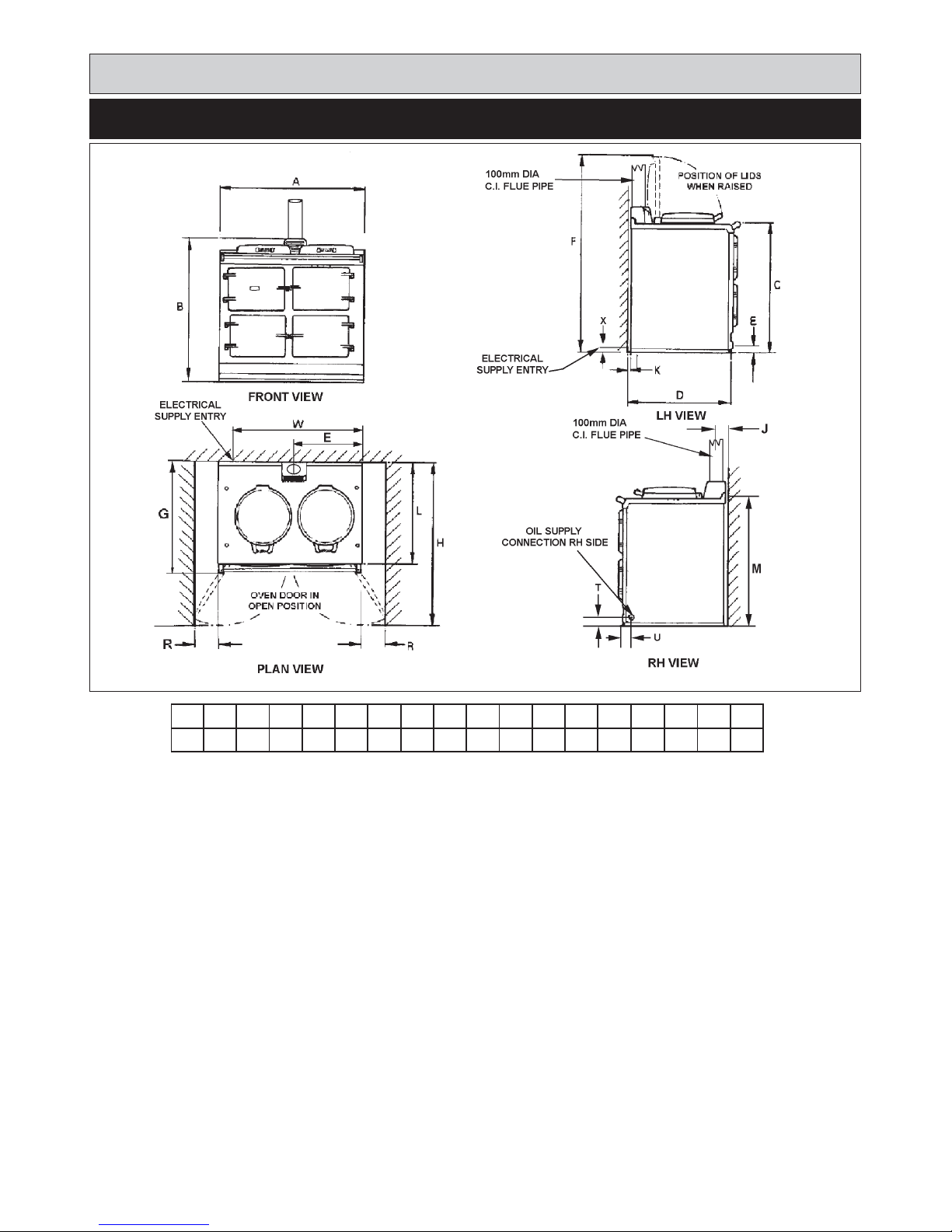
TECHNICAL DATA - AGA OC3
FIG. 1 DESN 514131 A
ABCDEFGHJKLMRT
mm
987
967 851 679 467
1450
756
1125
64
3
698 889 116 41
PLEASE NOTE: SIDE CLEARANCE DIMENSION R IS ALSO REQUIRED ON THE LH SIDE FOR THE BAKING OVEN
DOOR.
COOKER DIMENSIONS
When surveying for a cooker installation the actual clearance for the ‘body’ of the appliance should be increased overall
by 10mm beyond the figures quoted above. This allows safe margin to take into account the natural dimensional variations
found in major castings. In particular the width across the appliance recess could be critical.
OIL CONNECTION - OC3
1/4” BSP supply pipe with 1/4” BSP to 10mm elbow fitting provided.
Site requirements
U39W
867X60
Page 5

5
Oil Inlet R1/4 (1/4” BSP Taper Ext)
Electrical Supply 230V ~ 50Hz 3 amp Fused
Flue Outlet 100 mm
CO
2
% IN FLUE MANIFOLD 6.5 - 7.0
(COLD)
CO (MAX) 62 ppm (Nominal rate)
NOx (MAX) 106 ppm (Nominal rate)
Smoke 0 - 1
Fuel - Kerosene Class C2
Unpacked Weight of Appliance - 478 Kg
Firing Rate - 0.25 l/hr
Approximate Weekly Consumption -40 litres
(8.8 gallons)
TECHNICAL DATA - CONTINUED
BURNER NOZZLE (US g/h)
0.30 @ 60° H (DANFOSS)
5.2 (80)
15
9.5
4.1 cc/min
2.52 kW
OIL PRESSURE Bar (psi)
OIL BURNING RATE cc/m (FIRING)
HEAT INPUT kW (FIRING)
OIL BURNING RATE (AVERAGE)
OIL BURNING RATE (AVERAGE)
BURNER
IMPORTANT:
z
This appliance must only be used with Kerosene
Class C2 complying with BS. 2869.
z
A fire valve MUST be fitted in the oil supply line.
z
The supplied in line filter MUST be fitted.
The installation of the appliance must be in accordance
with the relevant standards. It should also be in
accordance with the relevant Codes of Practice.
Appliance Hearth: The surface temperature of the floor
below the appliance does not exceed 100ºC. However
this appliance must be installed on a solid floor or base of
incombustible material which is capable of supporting the
total weight.
The location chosen for the appliance must permit the
installation and the provision of a satisfactory flue and an
adequate air supply. The location must also provide
adequate space for servicing and for air circulation around
the appliance. See ‘Installation of the Appliance’.
The space in which the appliance is to be fitted must have
the following minimum dimensions:
Between wall and LH side of appliance - 10mm
Between wall and RH side of appliance - 10mm
SHOULD THE WALL PROJECT BEYOND THE FRONT
OF THE APPLIANCE. WHEN IT MUST BE INCREASED
TO 116mm.
Above the raised insulating cover - 60mm
In addition, adequate clearance must be available at the
front of the appliance to enable it to be operated and
serviced. Flue pipes and fittings must not be closer than
25mm to combustible materials and where passing
through a combustible partition such as a ceiling or roof,
must be enclosed in a non-combustible sleeve providing
an air space of at least 25mm.
Spaces around flue pipes passing through walls or floors
should be sealed against the passage of smoke and
flame.
Where the cooker is to stand in a recess or against a wall
which is to be tiled, in no circumstances should the tiles
overlap the cooker top plate.
INTRODUCTION
REGULATIONS
LOCATION
Site requirements
Page 6

SEE FIG. 2
The oil supply connection between the storage tank and
the oil pipe should be run in copper or steel pipe with a
minimum diameter of 10mm. Galvanised pipes and
fittings should not be used. Annealed copper pipe is
preferred with flare type manipulative fittings. Capillary
fittings with soft solder should not be used. Steel pipes
should be joined using taper threads.
All pipe work and fittings must be completely airtight. Only
oil resistant compounds and PTFE tape should be used
when making joints. Pipe work must be protected against
damage whether fitted above or below ground.
The size and arrangement of pipe work will depend upon
the distance and height of oil storage tank in relation to
the oil pump inlet.
The oil line from the storage tank to the appliance
must be fitted with a remote acting fire valve
operating at 140ºF (65ºC), fitted with an appropriate
length of capillary to enable the valve body to be
located externally at the point where the oil line enters
the building. The heat sensing phial of the fire valve
MUST be fitted in an appropriate position to protect
the building.
The paper element oil filter supplied with the appliance
must be fitted on the oil pipe line and isolation valve must
be fitted, as close to the cooker as possible in an
accessible position. A fire valve must be installed to
protect the property and the phial fitted in the clips
provided.
Aflexible pipe connection, is supplied to fit between the oil
supply pipe and the oil pump for ease of burner removal.
When positioning the tank, due consideration should be
given to appropriate access for fuel delivery vehicles.
Positioning should comply with the relevant standards.
The tank should be complete with the following:
1. Sludge cock (steel tanks)
2. Outlet valve and filter
3. Contents indicator
4. Vent pipe
To prevent entry of water or fitted with return bend.
5. Fill pipe and screw cap (50mm black pipe)
The use of open lids to fill tanks is not recommended.
Steel Tanks - should be mounted on suitable supports. If
of masonry, a damp proof membrane should be
positioned between the tank and its supports to prevent
the steel from rusting when in direct contact with water.
Steel tanks should slope 20mm for each 1m run from the
oil outlet towards the sludge cock (opposite end).
Plastic Oil Tanks - UV Stabilized, plastic tanks are a
modern alternative to steel. These green tanks are
protected against sunlight and do not need to stand on
piers. They do however need to be supported over their
entire base area. Ideally 50mm smooth faced garden
slabs bedded down onto sand or a smooth concrete base.
The single tapped outlet makes them more suited to
single pipe gravity feed.
OIL PIPE LINE
6
OIL STORAGE
FIG. 2 DESN 514132 B
Site requirements
Page 7

7
The flue system must be installed to the regulations in
force.
Information
Mean flue gas temperature 260ºC.
The appliance requires a minimum negative chimney
draught of 1.0mm W.G. (0.04” WG) with the burner on.
Maximum chimney draught 3.7mm (0.15” WG). Draughts
in excess of this will require a draught stabilizer fitted
either in the chimney or flue pipe and in the same
compartment.
Due to the range in flue gas temperature a brick chimney
should be fitted with a suitable multi fuel stainless steel
flexible liner. Factory built chimneys must comply with the
relevant standards.
The cross-sectional area of the flue serving the appliance
must not be less than the equivalent area of 100mm
diameter flue pipe, and be at least 4.5m high.
The flue pipe must not be less than 100mm internal
diameter. Flue pipes and fittings between the appliance
and the chimney should be constructed from one of the
following materials:
a. Cast Iron
b. Mild steel, acid resistant vitreous lined
Chimney Terminations
All chimneys should terminate above roof level, or with
the relevant standards in force.
Chimney Cleaning
Ensure there are accessible airtight flue cleaning doors in
order to obtain access to the complete chimney . Providing
the appliance is operating correctly, an annual chimney
flue cleaning will suffice, but if in doubt arrange for a half
yearly clean.
FLUE SYSTEM
FIG. 3
DESN 514133DESN 513932
Site requirements
Page 8

8
The appliance can only be installed in a room which
meets the ventilation regulations in force. But, in any
event the room must have a permanent vent of minimum
free air area, see below.
Detailed recommendations are given in the relevant
standards and codes of practice. The following notes are
intended for general guidance.
1. Combustion and ventilation air supply to oil fired
appliances has to comply with the relevant standards
and codes of practice. The air supply requirement for
oil fired appliances is 550m
2
per kW of maximum rated
output above 5.0 kW.
2. The combustion air supply to open flued appliances
should normally be provided at high level into a room
where it will not cause discomfort by creating a cold
draught across the floor.
3. If combustion air is supplied through an under floor
duct the grilles at each end should be positioned in the
vertical plane to reduce risk of blockage. Ducts should
be sized so as to reduce resistance air flow.
4. Extract fan should be positioned as far away from the
open flue as possible and should have a sufficient
dedicated air supply. To undertake a test the oil fired
appliance, should be set in operation and the doors
and windows of the room containing it should be
closed. The extract fan should then be run at its
maximum setting. The oil fired appliance should then
be run at its maximum setting. The oil fired appliance
should be observed to operate satisfactorily both
before and after the fan is switched on.
5. It is preferable for the air supply for an extract fan to be
located where it can serve the fan without the air
stream passing close to the oil fired appliance.
6. Oil fired appliances must not draw combustion air
from a garage.
Wiring external to the appliance must be installed in
accordance with the relevant standards, wiring
regulations and any local regulations which apply. The
appliance is supplied for 220/230 Volt - 50 Hz and a fuse
wiring of 3 amps.
The method of connection to the mains supply should
facilitate complete electrical isolation of the appliance, by
the use of a fused double pole switch having a contact
separation of at least 3mm serving only the appliance.
The point of connection to the mains should be readily
accessible and adjacent to the appliance. The installation
should be protected by a 30mA Residual Current Circuit
Breaker (RCCB).
The minimum requirement for the power cable is that it
should be a 3 core PVC sheathed flexible cord (85ºC min)
at least 0.75mm
2
(24 x 0.2mm) to the relevant standard.
WARNING: THIS APPLIANCE MUST BE EARTHED.
In the event of an electrical fault after installation of the
appliance, preliminary electrical system checks must be
carried out i.e. earth continuity, short circuit, polarity and
resistance to earth.
For wiring instructions, see wiring diagram.
AIR SUPPLY
OC3
30 cm
2
MODEL MIN. AIR REQUIREMENT
Site requirements
ELECTRICAL SUPPLY
Page 9

9
Site requirements
WIRING DIAGRAM
FIG. 5
X1 - CONTROL BOX WIRING
BASE
X2 - 6 POLE CONNECTOR
X3 - 6 POLE CONNECTOR
(REF. ONLY)
PE - PHOTOCELL
P - OIL PUMP
T - IGNITION TRANSFORMER
VL - OIL VALVE
AP - AIR PRESSURE SWITCH
M - FAN MOTOR
H - OIL PRE-HEATER
TS - TEMPERATURE SWITCH
PT - PULSE TIMER
RL - RELAY
R1 - RESISTOR
Page 10

10
Installation requirements
1. Check that the hearth is level, then remove the
appliance from its transit wooden pallet.
2. Connect and terminate the flue system in accordance
with the regulations in force.
NOTE: SMOKE/SMELL EMITTED DURING INITIAL
USAGE
During initial usage of operation of the cooker,
smoke/smell may be emitted and is normal and not a fault
with the appliance, it is therefore advisable to open doors
and or windows to allow for ventilation.
SITE LOCATION
OVEN VENT AND FLUE BREAK PIPE CONNECTION
FIG. 5
DESN 514591
Page 11

Installation requirements
Prior to assembly fix (4) hex head screws (M6 x 25mm
long) (marked A) to the burner housing, from the rear for
fixing the burner.
To ensure correct fitting of burner, it is important that the
95 dia holes in the burner housing and fire barrel adaptor
are in line with each other.
During assembly of the appliance, adjust the position of
the burner housing by loosening the (2) screws ‘B’ and (2)
nuts fixing the top flange burner housing to the front plate.
When the burner holes are in line, fit (4) countersunk
head screws marked ‘C’ to fix the position of the burner
housing to the fire barrel adaptor. DO NOT overtighten
these screws ‘C’ to prevent distortion of the burner
housing face, or to pull the fire barrel out of position.
On completion of the adjustment, tighten the screws fixing
burner housing to front plate.
Ensure to seal the gap around the burner hole by corking
rope between burner housing and fire barrel adaptor
plate.
BURNER HOUSING TO BARREL
ALIGNMENT
FIG. 6
DESN 514590
11
Page 12

SEE FIG. 7
1. Make electrical connections to terminal strip as wiring
diagram. (See Fig. 7).
SEE FIG. 8
1. The sensing phial of the overheat stat should located
on the clip provided.
2. Connect the flexible hose to the outlet pipe from the oil
feed.
3. Before connecting the flexible oil pipe to the pump
inlet, open the stop valve slowly and run off some of
the oil into a receptacle to establish an air free supply
to the pump. Make the connection onto the oil pump
tight and leave valve open.
12
Commissioning Instructions
ELECTRICAL CONNECTION
FIG. 7
DESN 514587
DESN 514588
FIG. 8
OIL PUMP CONNECTION
Page 13

Checks to ensure electrical safety should be carried out
by a competent person.
SEE FIG. 9
Remove the bleed screw from the manifold and fit an oil
pressure gauge with R 1/8 connection to check the pump
output pressure.
Switch on the Electricity
Set the cooker oven thermostat to position 4, wait 2
minutes for the pre-heater. The burner should run on prepurge for 10 to 20 seconds, with the ignition spark
energised. The oil solenoid valve should then open
allowing the burner to fire.
Until all the air from the oil pump is flushed out there may
be some flame instability resulting in the burner locking
out.
This will be shown by the burner stopping and the
illumination of the signal light in the reset button of the
control box (See Fig. 10). In this event, wait at least one
minute, then press the reset button to restart.
NOTE: This appliance is fitted with a pulse burner which
has a four minute on and four minute off cycle.
SEE FIG. 9
Whilst the burner is running, vent air from the pump by
slackening the pressure gauge connection sufficient to
allow air to bleed out. When bubble free oil seeps out
retighten.
SEE FIG. 9
After 15 minutes:
Whilst the burner is running, check the oil pressure on the
gauge. Wait for 30 seconds after ignition, for the burner to
establish the full firing rate.
If the pressure gauge is not indicating the correct reading
then adjust the pressure by turning the pressure regulator
clockwise to increase or anti-clockwise to decrease the
pressure until the pressure gauge reads 5.2 bar (80
Ibf/in
2
).
Switch off the burner , remove the pressure gauge and refit
the bleed screw.
13
Commissioning Instructions
ELECTRICAL CHECK
FIG. 9
DESN 513581
FIT PRESSURE GAUGE
VENT OIL PUMP
FIG. 10
DESN 514584
ADJUST OIL PRESSURE
Page 14

SEE FIG. 11 & 12
The air control of the burner is factory pre-set, however
small adjustments may be necessary to suit the site
conditions.
Turn burner on.
After 15 minutes, remove screw. Insert the sensing end of
a portable indicator to check the CO
2 (Carbon Dioxide)
level. Adjust the burner air intake until a reading of 6.5 -
7.0 is recorded on the indicator.
Check Smoke
Remove the CO
2 sampling tube and using the same hole
for flue sampling, insert the sensing end of a Baccarach
Smoke Pump and check that the smoke does not exceed
0 - 1 on the scale. Replace the screw.
NOTE: Ensure that the sampling screw is fitted correctly
as this forms part of the cooker combustion circuit.
Take care to fit shroud and avoid unnecessary enamel
contact.
14
Commissioning Instructions
SET COMBUSTION AIR
FIG. 11
DESN 514579
FIG. 12
DESN 513931
Page 15

In the event of flame failure the control box should cut off
the oil supply by closing the solenoid valve. The reset
buttons will then be illuminated.
WAIT 1 MINUTE BEFORE RE-SETTING THE
CONTROL BOX.
In the event of the appliance overheating, the burner is
protected by a manual reset thermostat. When tripped,
the thermostat will cut-off the oil supply causing the reset
to be illuminated.
1. Advise the user that, for continued efficient and safe
operation of the appliance, it is important that
adequate servicing is carried out at regular 12 monthly
intervals.
2. Hand the operating instructions to the user and
demonstrate the correct operation of the appliance
and system controls.
3. Leave the installation and servicing instructions with
the user.
Commissioning Instructions
ANCILLARY CONTROLS CHECK
15
OVERHEAT THERMOSTAT
INSTRUCT THE USER
Page 16

16
For further advice or information contact
your local Aga Specialist
With Aga’s policy of continuous product
improvement, the Company reserves the right to
change specifications and make modifications to
the appliance described and illustrated at any time
Manufactured by
Aga
Station Road
Ketley Telford
Shropshire TF1 5AQ
England
www.aga-web.co.uk
www.agacookshop.co.uk
www.agalinks.com
 Loading...