

Page 1
Gas Fired Cookers
4/01 EINS 511502
Installation Instructions for
Aga Gas Power Vent Fired Range
Models: G.C. P.V. (2 Oven) N.G. and LP.G,
Tx.’itjw;
G.E. P.V. (4 Oven)
For U.S. and Candían Markets
NOTE: THESE INSTALLATION INSTRUCTIONS SHOULD BE LEFT WITH THE APPLIANCE AND THE USER
TO RETAIN FOR FUTURE REFERENCE.
The Gas fired ranges are delivered unassembled. Before installation can be made, the site is inspected for
suitability by an Authorised Aga Distributor and corrected where necessary to conform with local installation codes
or in the absence of local codes with:
In Canada:
The CAN/CGA-B149 installation codes
In U.S.:
The National Fuel Gas Code ANSI Z223 1-latest edition.
Assembly is undertaken on site by the same Aga Distributor to ensure correct performance and safety.
INSTALLATION
It is essential that the base or hearth on which the range stands should be level and strong enough to support the
weight of the range.
Approximate weights;
Models G.C. - 406kg (9001b)
G.E, -585kg (12901b)
The top face of the hearth must be of non-combustible material for a minimum thickness of 12mm (1/2) and
comply with the current Building Regulations and National Fire Laws,
The location must also provide adequate space for servicing and air circulation around the range.
Page 2

WALL TILING
If the cooker is to stand in a reoess or against a wall which is to be tiled, in no circumstances should the tiles
overlap the range top plate.
GAS SUPPLY - U.S. PIPE THREADS
NOTE- A MANUAL VALVE MUST BE INSTALLED IN AN ACCESSIBLE LOCATION IN THE GAS PIPE
EXTERNAL TO THE APPLIANCE FOR THE PURPOSE OF TURNING ON OR SHUTTING OF GAS TO THE
APPLIANCE .
ALL GAS CONTROLS MUST BE U.S. PIPE THREADS.
Maximum Heat Input: 4,4kW (15,000 Btu/h)
The maximum gas inlet pressure at the appliance must not exceed 10 inches w.g. for Natural Gas, 14 inches w.g.
for L.P. Gas, The minimum gas inlet pressure at the appliance must be 5 inches w.g. Natural Gas and 11 inches
w.g. L.P. Gas to enable the correct manifold pressure to be obtained.
The appliance and its individual shut-off valve must be disconnected from the gas supply piping system during
any pressure testing of that system attest pressures in excess of 1/2 psig (3.5kPa), The appliance must be
isolated from the gas supply piping system by closing its individual manual shut-off valve during any pressure
testing of the gas supply piping system at test pressure equal to or less than 1/2 psi (3.5kPa).
On completion test the gas installation for soundness and purge. Leak testing of the appliance shall be conducted
according to manufacturer’s instuctions.
NOTE; Use soapy water solution on new gas connections to ensure there are no gas leaks.
AIR SUPPLY
Kitchen or Internal Air Supply . . ,
The appliance can only be installed in a room which meets ventilation regulations in force but in any event the
room must have a permanent vent of minimum free air area 36cm г (5.Sin 2 ).
In the event of an extractor fan being fitted in the vacinity of the range, compensatory ventilation will be required
to satisfy the demands of the fan without influencing combustion efficiency and flue conditions.
ELECTRICAL
IIO/I2OV6OHZ 10 AMP FLEXIBLE CORD AND PLUG PARALLEL TYPE. The appliance when installed, must be
electrically grounded in accordance with local codes or, in the absence of local codes, with the National Electrical
Codes ANSI/NFPA 70.
An electrical socket must be provided within 6 feet of the LH side of the appliance and easily accessible to the
user to disconnect. Do not position socket above the appliance.
WARNING
Electrical Grounding Instructions
This appliance is equipped with a (three-prong) grounding plug for your protection against a shock hazard and
should be plugged directly into a proper receptacle. Do not cut or remove the grounding prong from this plug.
Page 3

VENT SYSTEM
Products of combustion discharge is by a fan powered vent pipe 50mm (2in) diameter which can reach up to 6
metres (19.5ft) in length through a maximum of 6 x 90“ bends or 9 metres (29ft) with one bend. Exits from the
appliance can be from rear L.H. or R.H. sides, from the rear centre or from the under side (Figs. 2 & 3).
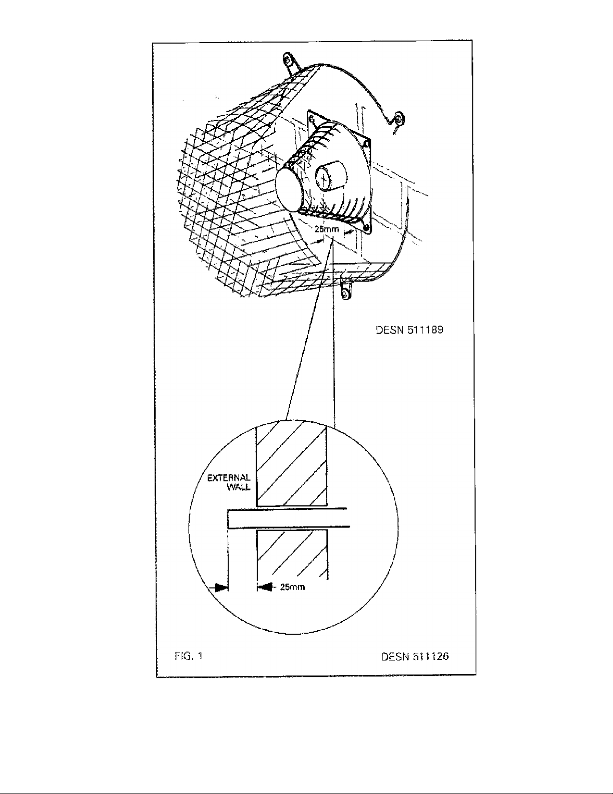
The vent pipe should exit through the outside wall fixing plate by 25mm (1 in) Fig, 1.
Page 4
Page 5
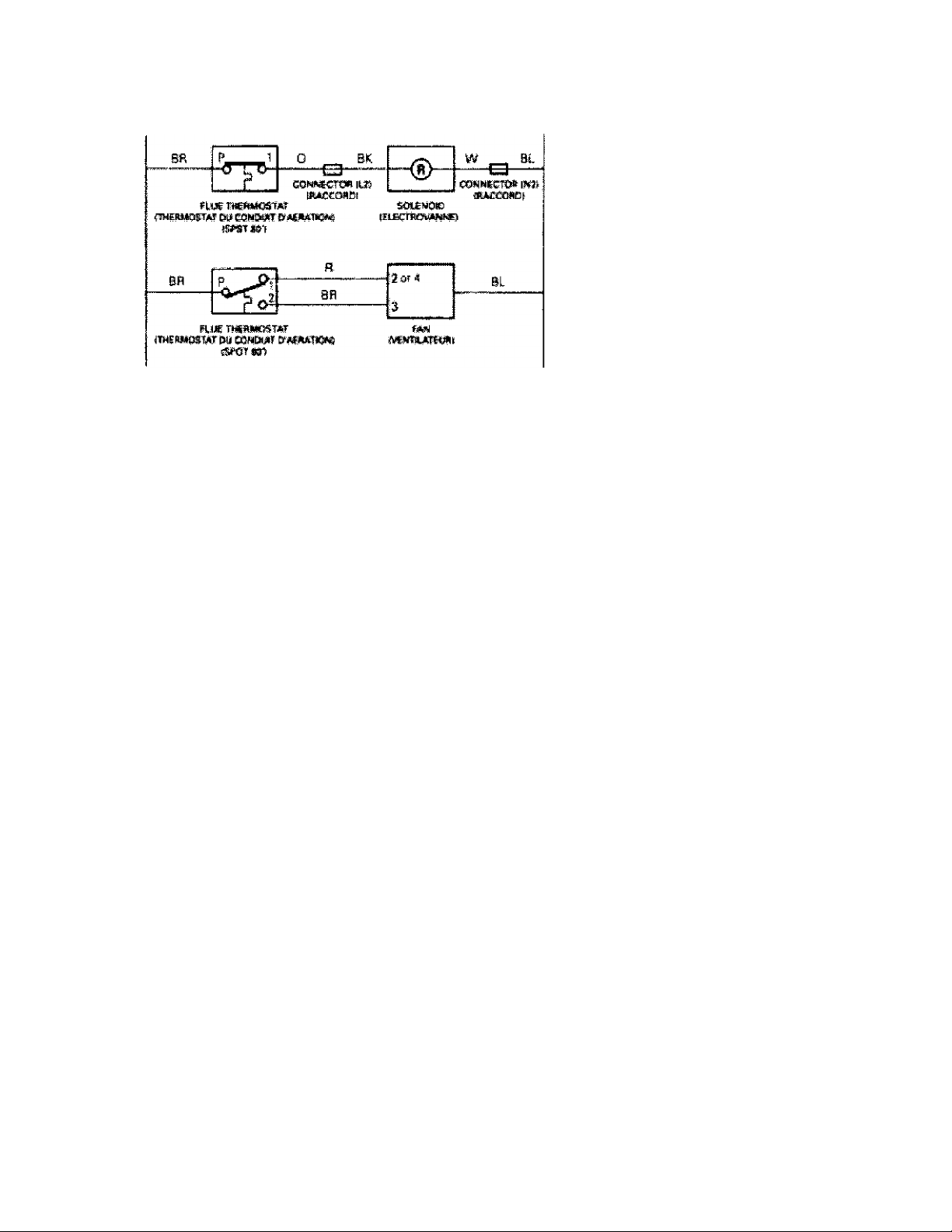
KlY
H
BL BLUE ^BLEUl
R BED iRWaK)
BK BUCK iNOIflJ
w №it“e iBuMJC;
0 QRBNGE iOfUkhiGEl
L iSOUS-miSiON)
N NEL/TRfeiNEUTREi
iMARRON]
when seniidr:^ ciffii?rots. Wiring
Lsfeel prisr ii'fesprwse^^ii
casise in^^epar and dangencxi:s opemt^n
Wis-dy tuoijer opes^isc« s«fvi(S!^g.
Page 6

i
я
Page 7

TERMINAL POSITION
1. The range must be installed so that the vent terminal is exposed to the external air and terminal
clearance comply with:
In U.S.: The National Fuel Gas Codes ANSI Z223 1 latest edition Section 7,7.
In Canada: CAN/CGA--B149 installation code.
2. Termination should be on a clear expanse of wall, the terminal being preferably not less than
355mm (14in) away from a corner, recess of projeotion.
3. A hole must be cut through an outside wall with the hole falling 1.5" from inside to outside face of
wall.
Openings in the walls behind or on the floor obelow the appliance must be sealed using the closure plate and
sealant provided.
DO NOT install the terminal under the following conditions;
(a) Within 300mm (12in) measured vertically from the bottom of an openable window, air vent or any
other ventilating opening.
(b) Within 300mm (12in) above adjacent ground level.
(c) Within 600mm (24in) of any surface facing the terminal.
(d) Within 355mm (14in) (U.S.) or 300mm (12in) (Canada) below eaves or balcony.
The terminal must be protected by the terminal protective guard (supplied) installed over the terminal to prevent
unauthorised contact with the hot terminal surfaces. (See Fig. 1).
Technical Specification
Models
Gas Type
Range Model
Main Burner injector
Pilot Burner Injector
Combination Gas Valve
Bypass Screw
Gas Burner Pressure
Combination Gas Valve
Pilot Assembly
GC
400
4212
1.20 mm
4.0
(inch w.g.)
GC and GE
Natural Gas
GE
400
4212
1.20 mm
4.0
(inch w.g.)
GC
180
4208
0.80 mm
10.0
(inch w.g.)
S.l.T. EUROSIT
JOHNSONS
GC and GE
LP.G
0.80
(inch
G
1i
42
1C
Page 8

GC PV (2 OVENS)
j:rZj№C!!BZra^—1.
A B C D
nnm
987
Q:
987
FROm* VIEW
PLAN VIEW
861 679
KNOCK OUT
HOLES FOfi
VÎNT PIPE
w
GAS CONNECTION R.H,
E f
G
H J
41 1314756 1125 39 3
KNOCK ourr
HOLÎS FOR
VENT PIPE
R.H. ^E VIEW
K
L
698 116 48
R
T L
S
65 37
Installation Ctoarances oi Combustibifl Cabinets Adlacent to Range
(762miTt
Page 9

GE PV {A OVENS)
A B C D
mm
14B7967 851 679
E :F G
41 1314 756
H J K L
1125 39 3 698
M N P Q
65 375 48 595
R S
116 66
LOCATION OF NAME PLATE
The model and serial numbers for this appliance are found on the name plate. These numbers must be used
when requesting advice from your Aga Distributor. The name plate is located on the inside of the outer burner
door.
Page 10

FIG. 4
COMMISSiONiNG
LIGHTING THE BURNER - (Fig. 4)
CAUTION: NO SMOKING OR NAKED LIGHTS
Open the burner outer door to expose the gas control combination valve.
CAUTION: BEFORE LIGHTING ENSURE THAT THE GAS VALVE KNOB 2 IS SET IN THE OFF POSITION. (SEE FIG. A) AND THE ELECTRICAL SUPPLY TO THE AGA IS SWITCHED ON.
1. Turn off union gas cock 1. Test the gas installation from the meter oook for soundness and purge,
2. Turn on gas supply to cooker and open gas cock 1. 3. Turn the gas valve control knob 2 anti-clockwise to the
position {see Fig. BV Press down and hold the knob in the position while depressing the piezo lighter 3 several
times until the pilot has lit. This can be observed through the viewing window 4.
4. When the pilot has lit continue to hold the gas valve control knob for approximately 30 seconds. If it goes out,
wait 3 minutes and repeat the procedure holding for a little longer.
5. When the pilot flame established, rotate the gas valve control knob 2 anti-clockwise to its low fire position (see
fig, cy Where upon the main burner will automatically light. Leave in the low fire position for at least 30 minutes.
Page 11

OFF
^ ìGNITiON
WHITE BLOCK
LOW FIRE
GREEN BAND
NORMAL RUNNING
6. After 30 minutes, check the burner gas pressure, (i) Turn the gas control knob 2 to PILOT position (see Fig^).
Remove the main burner pressure test nipple plug 5 and fit pressure gauge. Turn gas valve control knob 2 to the
mid position of the green band.
(ii) Check burner pressure correctly corresponds to the data plate.
(iii) Cheok that the gas pressure is unaffected to the main burner when other gas appliances are used.
(iv) Turn gas valve control knob 2 to PILOT (see Fig. B). Remove the pressure gauge and replace gas nipple
Page 12

p[ug. Turn temperature control knob 2 to the mid position of the green band for normal running.
7. On the first lighting or if the cooker has been cold for a long time, moisture from the insulation may run down
the enamelled front of the cooker. This should be wiped off to prevent staining.
Once the correct setting has been confirmed the heat control will operate automatically to maintain the cooker at
full temperature.
NOTE: AFTER SEVERAL HOURS THE HEAT INDICATOR SHOULD BE ON OR ABOUT THE BLACK LINE IN
THE SILVER SECTION. IT MAY BE NECESSARY TO ADJUST THE CONTROL KNOB SLIGHTLY IN THE
GREEN BAND TO ACHIEVE THIS.
IF THE FLAME HAS EXTINGUISHED FOR WHATEVER REASON, WAIT THREE MINUTES (MINIMUM), BEFORE RE-LIGHTING.
NOTE: REMEMBER TO NOTE THE SETTING POSITION IF TURNING OFF THE COOKER
TO EXTINGUISH THE BURNER
Turn the gas valve control to the OFF position (see Fig. A).
Page 13

PILOT ASSEMBLY
Page 14

YEARLY SERVICE
It is recommended that the range be serviced every 12 months.
Arrange with the housholder that the range has been turned OFF the night before to ensure it is cold upon arrival.
1. WARNING: Disconnect Eiectric Supply before servioing.
2. Isolate the gas supply by turning off the service gas valve beneath the combination gas valve, Break the
heaxgon union connection nut.
3. Detach the inner burner door fixing screw and draw complete gas burner assembly clear of the combustion
chamber resting it on the floor of the range,
4. Remove the boiling plate, combustion chamber baffle and simmering plate.
5. Check conditions of flueways and combustion chamber and clean if necessary.
6. Lightly brush the perforated top of the gas burner and check that the burner venturi is free of lint and fluff.
NOTE: IT MAY BE NECESSARY TO DETACH THE PILOT ASSEMBLY AND REMOVE THE BURNER TO
ENSURE IT IS FREE.
7. Check the condition of the pilot thermocouple tip to ensure it is clean and free of carbon. Heavy heat oxidised
tips should mean the removal of the thermocouple and a new replacement. Examine and brush the pilot light
parts and examine the ignitor cable to ensure the PTFE insulation remains intact and is firmly connected to the
spark electrode. Clean any carbon away from the electrode.
8. Refit the gas burner assembly in reverse manner described in 3 and reconnect the gas supply at service gas
valve union.
NOTE: USE SOAPY WATER SOLUTION TO ENSURE THERE ARE NO GAS LEAKS.
9. Inspect and clean vent fan blades, remove debris using a soft brush, access to this fan can be made by
removing the R.H, and centre shroud.
10. Turn on the gas and electric supply and follow the procedure for lighting the burner.
11. Ensure that the pilot and main burner flame are burning evenly, the thermocouple is enveloped by the pilot
flame.
12. Visuallt check the main burner and pilot flame for correct flame pattern. An established main burner at high
fire will be predominantly blue with yellow tippings on an even height flame strip and be about 150mm (6in) high.
See Fig. 11. Ensure ail flameports have cross-lit and that the pilot light flame is free from sooting.
13. The maximum depth of any cabinets installed above the top cooking surface of the range must not exceed
330mm (13in).
NOTE: DO NOT ATTEMPT TO SERVICE THE RANGE YOURSELF, CONTACT YOUR LOCAL AGA
DISTRIBUTOR STATING THE MODEL AND SERIAL NUMBER OF THE APPLIANCE TOGETHER WITH YOUR
NAME AND ADDRESS.
REPLACEMENT PARTS
Page 15

In the event of a component failure which requires replacement, contact your local Aga distributor who will advise
and supply the necessary replacement.
Expendable components that will require replacing at some time or other are listed as follows:
Description
1. Pilot Thermocouple
2. Main Burner
3a. Pilot Burner Assembly N.G.
3b. Pilot Burner Assembly L.P.G.
4. Combustion Gas Valve
5a. Pressure Regulator N.G.
5b. Pressure Regulator L.P.G.
6. Combustion Chamber Door Seal
7. Solenoid Gas Valve
8. Venting Fan
9. Flue Thermostat
For further advice or information contact
your iocal distributor/stockist
VWth Aga-Rayburn's policy of
continuous product improvement,
the Company reserves the right to
change specifications and make
modifications to the appliances
described and illustrated at any
time.
RANGES
110 Woodcrest Road
Cherry Hill
NJ 08003
800.633.9200
www.ag a-ra nqes.com
 Loading...