

Page 1
NOTE: THESE INSTRUCTIONS SHOULD BE LEFT
WITH THE APPLIANCE AND THE USER TO RETAIN
FOR FUTURE REFERENCE.
Aga Gas Fired ranges are delivered unassembled.
Before installation can be made the site is inspected for
suitability by an Authorised Aga Distributor and corrected
where necessary to conform with local installation codes
or in the absence of local codes with:
In Canada:
The CAN/CGA-B149 installation codes.
In U.S.:
The National Fuel Gas Code ANSI Z223. 1-latest edition.
Assembly is undertaken on site by the same Aga
Distributor to ensure correct performance and safety.
It is essential that the base or hearth on which the range
stands should be level and strong enough to support the
weight of the range.
Approximate weights:-
Models GC (Open Flue) and GC (Direct Vent)
- 408kg (900lb)
Models GE (Open Flue) and GC (Direct Vent)
- 585kg (1290lb)
The top face of the hearth must be of non-combustible
material for a minimum thickness of 12mm (1/2in) and
comply with current Building Regulations and National
Fire Laws.
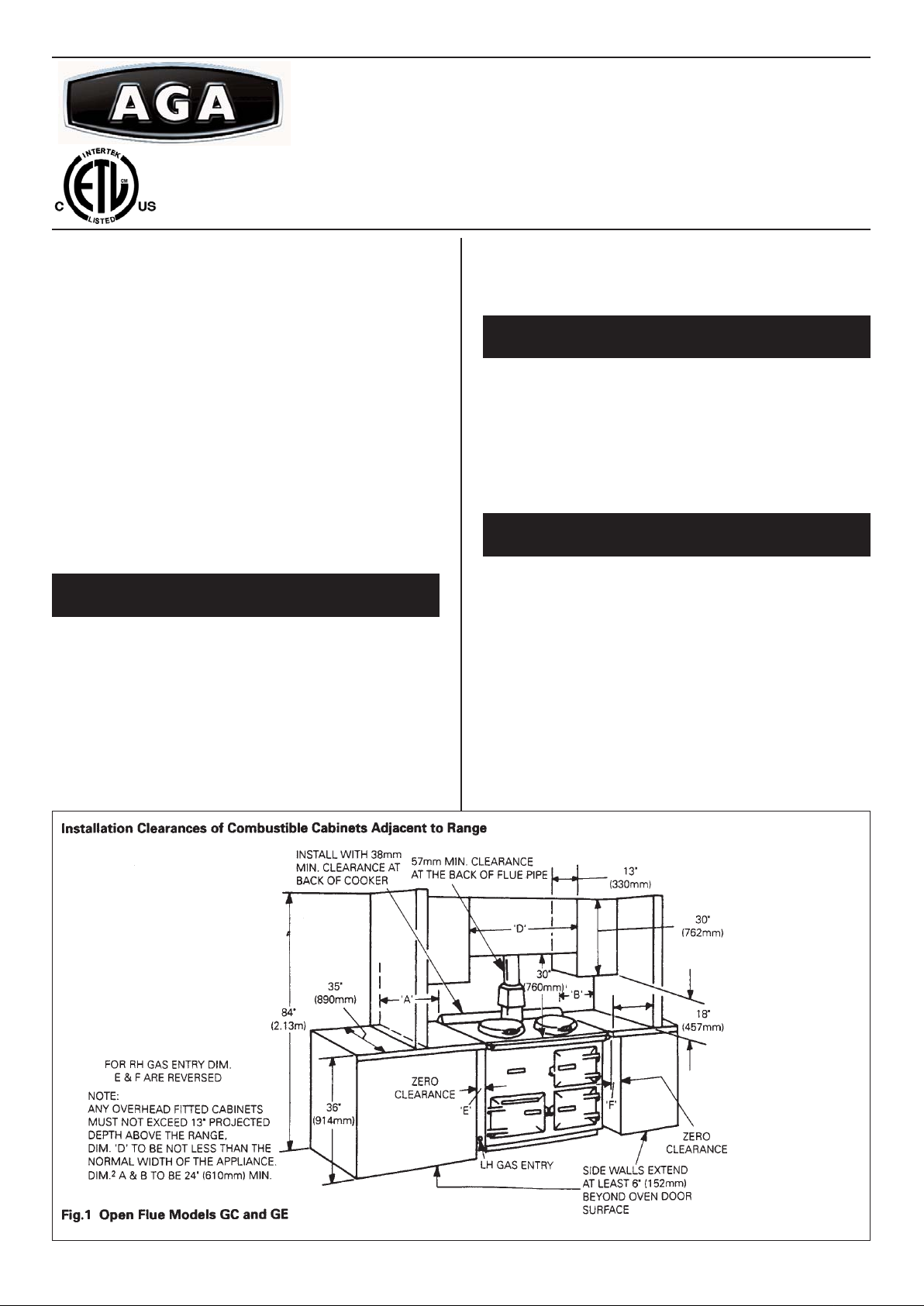
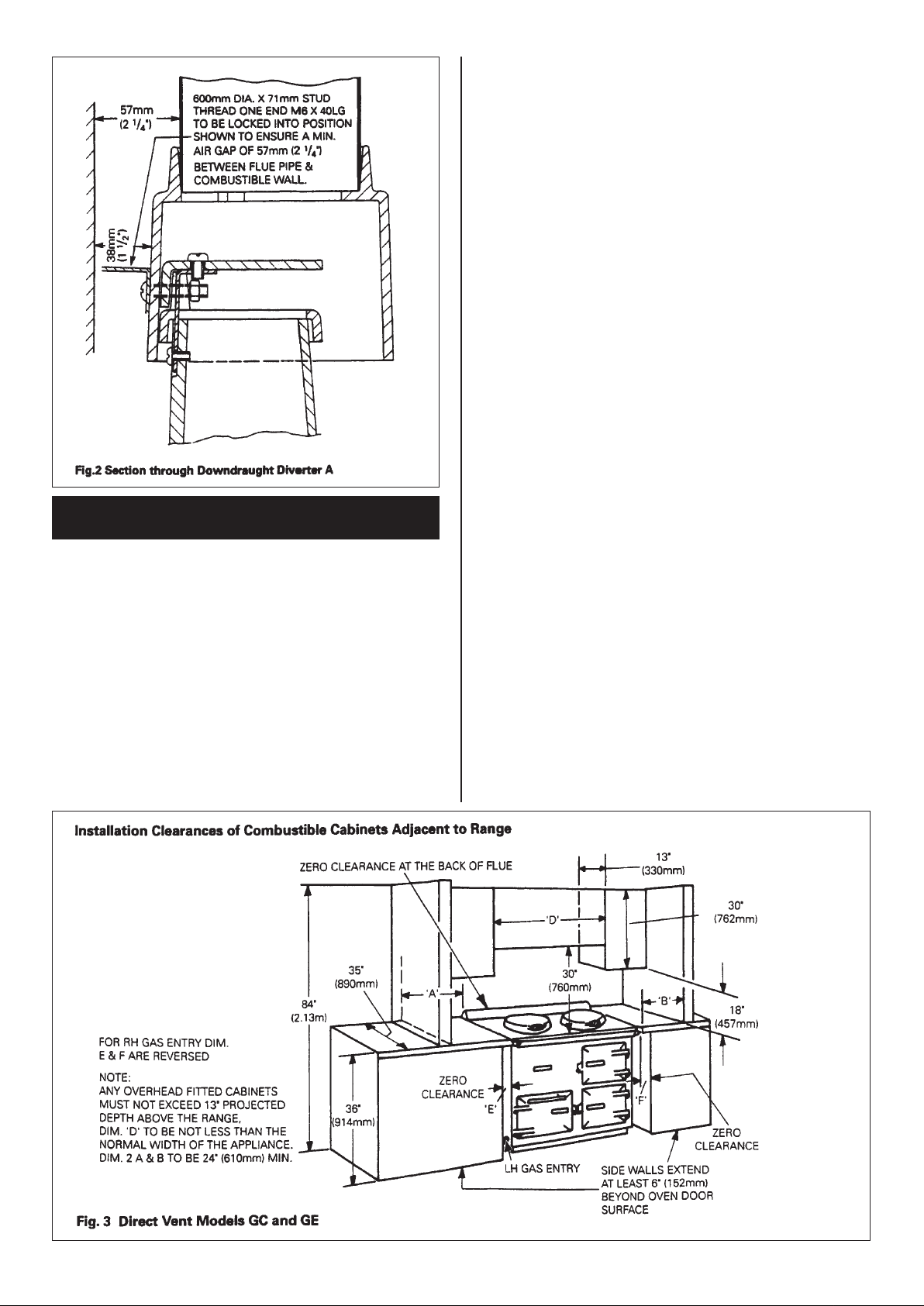
The wall behind the cooker draft hood and flue connector
must have a minimum air gap of 57mm (2 1/4”). Any
openings in the wall behind the range or in the floor under
the range must be sealed before appliance installation.
Ensure the draft hood is securely bolted to the support
spigot as shown in Fig. 2.
NOTE: THIS IS NORMALL Y FITTED AND SECURED BY
THE FACTORY BEFORE DESPATCH.
The wall behind the range must be the outside wall for
the venting of flue products. Wall thickness between
150mm (6 in) and 355mm (14 in) can be catered for at the
same time as site inspection.
Alternatively, special lengths can be offered to order up to
a maximum of 610mm (24 in) long.
Open Flue - Models GC and GE
Installation Instructions for Aga Gas Fired Range
Models: GC Open Flue Range (2 Oven)
GC Direct Vent Range (2 Oven)
GE Open Flue Range (4 Oven)
GE Direct Vent Range (4 Oven)
For U.S. and Canadian Markets
1 04/08 EINS 33644
BASE OR HEARTH
OPEN FLUE RANGE MODELS GC AND GE
DIRECT VENT RANGE-
MODELS GC AND GE
Page 2
2
A 100mm (4in) Type B Gas Vent must be used and fastened
by screw to the draft hood flue collar.
U.S.
The gas vent must be connected to a chimney or
independently and in accordance with Chapter 26, chimney ,
Gas Vent and Fireplace Systems of the current issue of
Equipment and Volume of the ASHRAE Handbook. The gas
vent proximity to combustible materials must be installed as
recommended in ANSI/NFPA 211 and according to
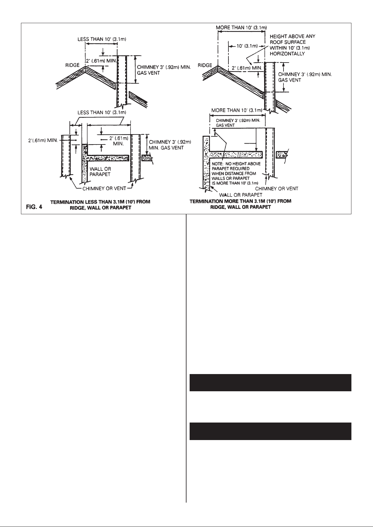
manufacturers instructions. Chimneys and vents shall
terminate above roof level and in accordance with the
requirements of the current issue of ANSI/NFPA 211 (see
diagrams) and be at least 1.53m (5ft) above the flue collar
of the draft hood outlet.
Part 7, Venting of Equipment, outlined in the current
National Gas Code ANSI Z223 - latest edition gives detailed
guidelines on all these aspects.
Canada:
The gas vent must be connected to a chimney or
independently and in accordance with the CAN/CGA - B149
installation codes.
The air gap between vent and combustible materials must
be given for the following types of vent:
(i) Type B Vent - 25mm (1in) minimum.
(ii) Single wall vent connector - 150mm (6in) minimum.
Listed connectors passing through combustible walls and
partitions must be guarded by a ventilated metal thimble not
less than 200mm (8in) diameter.
Chimneys and vents shall terminate above roof level and in
accordance with the requirement of the current issue of the
CAN/CGA - B149 Installation Code (Code W) (see
diagrams) and be at least 1.53m (5ft) above the flue collar
of the draft outlet.
1. If suitable lined brick chimney is used it must be
swept before connection and not less than 150mm
(6in) internal diameter.
2. The top of the chimney should be fitted with an
approved Terminal.
3. The flue route to the chimney should be as direct as
possible. Resistance in the form of directional change
should be kept to a minimum. Right angle bends and
horizontal runs should be avoided.
4. The chimney terminal should terminate at the highest
possible point, preferably in a freely exposed position.
Termination at the roofs eaves is unacceptable.
5. The Aga Distributor or Local Gas Company should be
advised where any doubt arises as to the suitability of
the flue.
6. Approved factory made chimneys are acceptable with
VENT CONNECTION
Page 3
3
the appliance and should not be less than (4in) internal
diameter.
7. In the event of an extractor fan being fitted in the vicinity of
the range, compensatory ventilation will be required to
satisfy the demands of the fan without influencing
combustion efficiency or chimney flue condition.
Direct Vent - Models GC and GE
The location chosen for the appliance must permit the
provision of a satisfactory flue termination.
The location must also provide adequate space for servicing
and air circulation around the range.
Should the installation of the appliance be in an unusual
location or restricted space, special procedures may be
necessary and the following current codes give detailed guide
lines on this aspects:
U.S.: The National Fuel Gas Code ANSI Z223.
1-latest edition.
Canada: The CAN/CGA B -149 installation codes.
The following notes are intended to give general guidance.
1. The range must be installed so that the flue terminal is
exposed to the external air and terminal clearances comply
with:
In U.S.: The National Fuel Gas Codes ANSI Z223 1-latest
edition Section 7.7.
In Canada: CAN/CGA-B149 installation code.
2. Termination should be on a clear expanse of wall, the
terminal being preferably not less than 355mm (14in) away
from a corner, recess of projection.
3. A hole must be cut through an outside wall as indicated in
Fig. 6 with the hole rising from inside to outside face
of wall.
DO NOT install the terminal:-
(a) Within 300mm (12in) measured vertically, from the
bottom of an openable window, air vent or any other
ventilating opening.
(b) Within 300mm (12in) above adjacent ground level.
(c) Within 600mm (24in) of any surface facing the
terminal.
(d) Within 355mm (14in) (U.S.) or
300mm (12in) (Canada) below eaves or balcony.
The direct vent terminal must be protected by a terminal
protective guard installed over the terminal to prevent
unauthorised contact with hot terminal surfaces.
See Fig. 8.
4. All jointing faces providing primary air and flue exhaust
paths, must be sealed in an airtight fashion, with particular
emphasis on the following locations:
(a) Air intake tube joints to be sealed with silicone adhesive
provided.
(b) Combustion chamber top sealed with a fire-cemented
gasket to the outer barrel.
(c) Fire cement joints between underside contact faces of
hotplates and simmering plate with cement provided.
(d) Gasket between flue intake/exhaust manifold.
Gasket provided.
The air inlet/products outlet direct vent, and the terminal of the
appliance must not be less than 300mm (12in) to combustible
material. The terminal is suitable for walls of 150mm (6in) to
355mm (14in) overall thickness.
For special lengths up to 610mm (24in), consult your local Aga
Distributor.
If the cooker is to stand in a recess or against a wall which is
to be tiled, in no circumstances should the tiles overlap the
range top plate.
NOTE: A GAS CONTROL VALVE MUST BE INSTALLED.
IN THE GAS PIPELINE EXTERNALL Y OF THE RANGE (NOT
SUPPLIED).
9.5mm (3/8in) N.P.T. Male connection near the front of the
range on the L.H. or R.H. side - Optional.
ALL GAS CONTROLS MUST BE U.S. PIPE THREADS.
Maximum Heat Input: 4.4 kw (15,000 Btu/h)
WALL TILING
GAS SUPPLY - U.S. PIPE THREADS
Page 4

GC, GE Open Flue Models
Maximum Heat Input: 4.4kw (15,000 (Btu/h)
GC, GE Direct Vent Models
The appliance and its individual shut-off valve must be
disconnected from the gas supply piping system during
any pressure testing of that system at test pressures in
excess of 1/2 psig (3.5kPa). The appliance must be
isolated from the gas supply piping system by closing the
individual manual shut-off valve during any pressure
testing of the gas supply piping system at test pressures
equal to or less than 1/2 psig (3.5kPa).
The model and serial numbers for this appliance are
found on the name plate. These numbers must be used
when requesting advice from your Aga Distributor. The
name plate is located on the inside face of the outer
burner door. The maximum gas inlet pressure at the
appliance must not exceed 12 inches w.g. (2.98kPa) for
Natural Gas and 14 inches w.g. (3.48kPa) for L.P. Gas.
The minimum gas inlet pressure at the appliance must be
4 inches w.g. (1kPa) Natural Gas and 10 inched w.g.
(2.248kPa) L.P. Gas to enable the correct manifold
pressure to be obtained.
4
LOCATION OF NAME PLATE
Page 5

In a cold range, difficulty may be experienced in maintaining
the main burner alight on initial light-up only. Should this
occur, set the control knob to the position. Depress knob
and light pilot. With the pilot flame established, release the
control knob gradually and rotate anti-clockwise to its low fire
position, whereupon the main burner will light. Leave in the
low fire position for at least 30 minutes.
NOTE: Any attempt to rotate the control knob before
release may result in damage.
After 30 minutes rotate the control knob further anti-clockwise
to the mid position in the green band for normal running.
INITIAL LIGHTING OF RANGE
5
Page 6

NOTE: DO NOT ATTEMPT TO SERVICE THE RANGE
YOURSELF. CONTACT YOUR LOCAL AGA DISTRIBUTOR
ST ATING THE MODEL AND SERIAL NUMBER TOGETHER
WITH YOUR NAME AND ADDRESS
In the event of a component failure which requires
replacement, contact your local Aga Distributor who will
advise and supply the necessary replacement.
Expendable components that will require replacing at some
time or other are listed as follows:-
Description
1. Pilot Thermocouple
2. Main Burner
3a. Pilot Burner Assembly N.G.
3b. Pilot Burner Assembly L.P.G.
4. Combination Gas Valve
5a. Pressure Regulator N.G.
5b. Pressure Regulator L.P.G.
6. Combustion Chamber Door Seal
Models
GC and GE - Open Vent/GC and GE - Direct Vent
Gas Type Natural Gas L.P.G.
Range Model GC/GE GC/GE
Main Burner 400 180
Injector
Pilot Burner Injector
N35 L23
Combination 1.00mm 0.60mm
Gas Valve or or
Bypass Screw 1.20mm 0.80mm
Gas Burner 4.0 10.0
Pressure inch w.c. inch w.c.
Combination S.I.T. EUROSIT
Gas Valve
Pilot Assembly JOHNSONS
6
REPLACEMENT PARTS
TECHNICAL SPECIFICATION
Page 7

7
Fig. 12 Pilot/Thermocouple DESN 512827
Page 8

It is recommended that the range be serviced at regular annual
intervals.
Arrange with the householder that the range has been turned
OFF the night before to ensure it is cold upon arrival.
The appliance and its individual shut-off valve must be
disconnected from the gas supply piping system during any
pressure testing of that system at test pressure in excess of 1/2
psig (3.5kPa). The appliance must be isolated from the gas
supply piping system by closing its individual manual shut-off
valve during any pressure testing of the gas supply piping
system at test pressure equal to or less than 1/2 psig (3.5kPa).
1. Isolate the gas supply by turning off the service gas valve
beneath the combination gas valve. Break the hexagon
union connection nut.
2. Detach inner burner door fixing screws and draw
complete gas burner assembly clear of the combustion
chamber resting it on the floor in front of the range.
NOTE: THERE IS SUFFICIENT LENGTH OF
THERMOSTAT CAPILLARY TUBE WITHOUT DETACHING
THE SENSING END FROM THE TOP OF THE ROASTING
OVEN.
3. Remove the boiling plate, combustion chamber baffle
and simmering plate.
4. Check conditions of flueways and combustion
chamber and clean if necessary.
5. Lightly brush the perforated top of the gas burner and
check that the burner venturi is free of lint and fluff.
NOTE: IT MAY BE NECESSARY TO DETACH THE PILOT
ASSEMBLY AND REMOVE THE BURNER TO ENSURE IT
IS FREE.
6. Check the condition of the pilot thermocouple tip to ensure
it is clean and free of carbon. Heavy heat oxidised tips
should mean the removal of the thermocouple and a new
replacement. Examine and brush clean the pilot light parts
and examine the ignitor cable and connector strip to ensure
the PTFE insulation cable, remains intact and strip is
firmly connected to the spark electrode. Clean any carbon
away from the electrode.
7. Refit combustion chamber baffle.
8. DIRECT VENT MODEL ONLY - GC AND GE.
Using a wire brush, lightly remove the old sealing cement
on the contact under faces of the hotplate and simmering
plates to the cooker, and lighly smear another cement
sealing coat provided, before refitting of hotplates.
9. Refit gas burner assembly in reverse manner described in
2 and reconnect the gas supply at service gas valve union.
On completion test the gas installation for soundness and
purge. Leak testing of the appliance shall be conducted
according to manufacturer’s instructions.
NOTE: USE SOAPY WATER SOLUTION ON NEW GAS
CONNECTIONS TO ENSURE THERE ARE NO GAS
LEAKS.
10.Turn on the gas supply and follow the procedure for
lighting the burner.
11.Ensure that the pilot and main burner flames are
burning evenly, the thermocouple is enveloped by the
pilot flame.
12.Visually check main burner and pilot flame for correct
flame pattern. An established main burner at high fire will
be predominantly blue with yellow tippings on an even
height flame strip and be about 150mm (6in) high. See Fig.
11. Ensure all flameports have cross-lit and that the pilot
light flame is free from sooting.
13.The maximum depth of any cabinets installed above the
top cooking surface of the range must not exceed 330mm
(13in).
8
With Aga's policy of continuous product improvement, the
Company reserves the right to change specifications and make
modifications to the appliance described and illustrated at any time.
Aga-Ranges
110 Woodcrest Road
Cherry Hill
NJ 08003
800.633.9200
Installer Servicing Instructions for Aga Models
GC and GE Open Flue Ranges and
GC and GE Direct Vent Ranges
YEARLY SERVICE
www.aga-ranges.comFor further advice or information please contact
your local distributor/stockist
 Loading...