

Page 1
Ellesmere
Standard Model
Electric Stove
INSTALLER: LEAVE THIS MANUAL WITH THE APPLIANCE.
CUSTOMER: PLEASE RETAIN THIS MANUAL FOR FUTURE REFERENCE.
For use in GB & IE (United Kingdom and Ireland)
Document No. : RH/ELEC/ELL/AS/AM – Iss 02/01/2020
File: Ellesmere Electric ECE-AS Standard_User_Man.doc
Page 2
AGA Ellesmere Electric Standard Stove
Installation & User Manual
PURCHASE, INSTALLATION INFORMATION & HEALTH & SAFETY
3
ELECTRICAL SAFETY TEST CERTIFICATE
6
IMPORTANT INSTRUCTIONS
7
THE DO’S & DON’Ts
8
STOVE DIMENSIONS
9
INSTALLATION ONTO A NON-COMBUSTIBLE HEARTH
10
UNPACKING AND TESTING APPLIANCE
12
WHAT COMES WITH THE STOVE
13
FITTING THE REAR WALL FIXING BRACKET
14
SETTING UP THE LOG SET & MEDIA
17
LOG SET - SAMPLE LAYOUT
18
OPERATING YOUR STOVE – UNDERSTANDING THE ICONS
20
MANUALLY OPERATING THE STOVE – INSTRUCTIONS
22
REMOTE CONTROL OPERATION – INSTRUCTIONS
23
STOVE RESET SEQUENCE
27
CARE AND MAINTENANCE
27
EXPLODED VIEW & PARTS LISTS
28
TROUBLE SHOOTING
30
SERVICE HISTORY
31
WARRANTY
32
SAFETY INFORMATION
WARNING
If the information in these
instructions is not followed exactly, a
fire or explosion may result causing
property damage, personal injury or
loss of life.
Do not store or use Petrol or any
other flammable vapors and liquids in
the vicinity of this or any other
TABLE OF CONTENTS
Please read and carefully follow all of the instructions found in this manual. Please pay
special attention to the safety instructions provided in this manual. The instructions included
here will assure that you have many years of dependable and enjoyable service from your
AGA Electric Stove.
Page 2
Page 3
AGA Ellesmere Electric Standard Stove
Installation & User Manual
Ref.
Description
Please Complete
1
Which retailer did you purchase the
stove from?
Name & Address of Retailer:
2
What date did you purchase your new
stove?
Purchase Date:
3
What was the name of the person
who installed your stove?
Full Name:
Contact Number:
5
What is the serial Number of your
stove?
This can we found inside the front
door above the bottom hinge
Serial Number:
6
What date was your stove Installed?
Installation Date:
7. The AGA Name, Model & Type
reference for this stove is
Name - Ellesmere Standard
Model – ELL/ELEC/A5S
Type – Electric
Reference
Description
Data
1
Maximum Heat Output
1.9 kW - (Equivalent to approx. 6,500 BTU's)
2
Minimum Heat Output
950 Watts
3
Flame Only Effect - LED Lights
25 watts - (Power Consumption)
4
Fuse Size inside 3 Pin Plug
10 Amp Rating
PURCHASE & INSTALLATION INFORMATION
Please complete the following form for reference when required:
Technical Data Summary:
AGA Reference Code:
Model Code Reference - ELL/ELEC/A5S
Page 3
Page 4
AGA Ellesmere Electric Standard Stove
Installation & User Manual
HEALTH & SAFETY REQUIREMENTS – PLEASE READ
1. If the electricity supply cable is damaged do not use the appliance until it has been replaced.
For safety reasons the replacement has to be carried out by a service agent or a similarly
competent electrician.
2. Caution: in order to avoid a hazard due to inadvertent resetting of the thermal cut out, this
appliance must not be supplied through an external switching device, such as a timer, or
connected to a circuit that is regularly switched on and off by the utility
3. Do not operate the appliance if it is damaged.
4. Repairs of electrical appliances must only be performed by a suitably qualified electrical
engineer. Should the appliance fail to operate, or in case of any damage, please contact the
retailer from whom the appliance was purchased.
5. Caution: some parts of this product can become very hot and cause burns. Particular
attention must be given where children and vulnerable people are present.
6. This appliance can only be used by children aged from 8 years and above and
persons with reduced physical, sensory or mental capabilities or lack of experience
and knowledge if they have been given supervision and/or instruction concerning
use of the appliance in a safe way and understand the hazards involved. However if
you do not deem the child or person competent only allow them to operate the stove
when a competent adult is in the room to supervise
7. CHILDREN OF LESS THAN 8 YEARS SHOULD BE KEPT AWAY UNLESS
CONTINUOUSLY SUPERVISED BY A COMPETENT ADULT.
If you are installing your appliance in to an existing chimney cavity
This stove MUST be installed on a Non Combustible Hearth - Ensure the floor area the
stove will sit on is flat and free from any loose materials
If applicable - if being fitted into a chimney opening ensure the flue has been
fully swept out, the chimney cavity should be sealed but an air vent must be
fitted so there can be a free flow air into the flue
To provide power to the appliance instruct a qualified electrician to install an earthed
power socket behind the stove unless one is already there. Ensure this socket can be
electrically isolated with a switch which is accessible, this must be connected to the
13 amp ring main of the house and covered by a RCB breaker
Must not be installed into a room with steam and water ingress such as a Kitchen or
Bathroom or a Wet Room
When installing & operating this stove there must be a free flow of air all around the
complete stove so a free flow of air can enter the rear air vent of the stove without any
restriction
Page 4
Page 5

AGA Ellesmere Electric Standard Stove
Installation & User Manual
HEALTH & SAFETY REQUIREMENTS – PLEASE READ
Never leave children unsupervised with an unguarded heater.
Never obstruct or cover the Stove or the heater Air Inlet and Outlet.
Never install or use this product where it may come in contact with water, moisture or
Steam i.e. Kitchen, Bathroom or Wet Room.
Never use aerosols or steam cleaners near this product.
Never route the electric cable near the heater outlet.
Never route the electric cable under carpets or floor coverings.
Never install this product close to curtains or any combustible materials.
Never use the heater to dry clothes or other objects.
Never remove the stove from the fireplace without isolating the electric supply, ensure
this stove is EARTHED
Page 5
Page 6
AGA Ellesmere Electric Standard Stove
Installation & User Manual
Manufacturer:
AGA Rangemaster
Product Name/Model:
Ellesmere Standard Electric Stove ELL/ELEC/A5S
Description:
Room heater
Certificate Number:
C 19-4649B
Test Standards:
EN 60335-2-30:2009 + A11:2012
EN 60335-1:2012 + A11:2014 + A13:2017
Tested at:
Kiwa Blackwood Compliance Laboratories
Blackwood, NP12 2DG,
United Kingdom
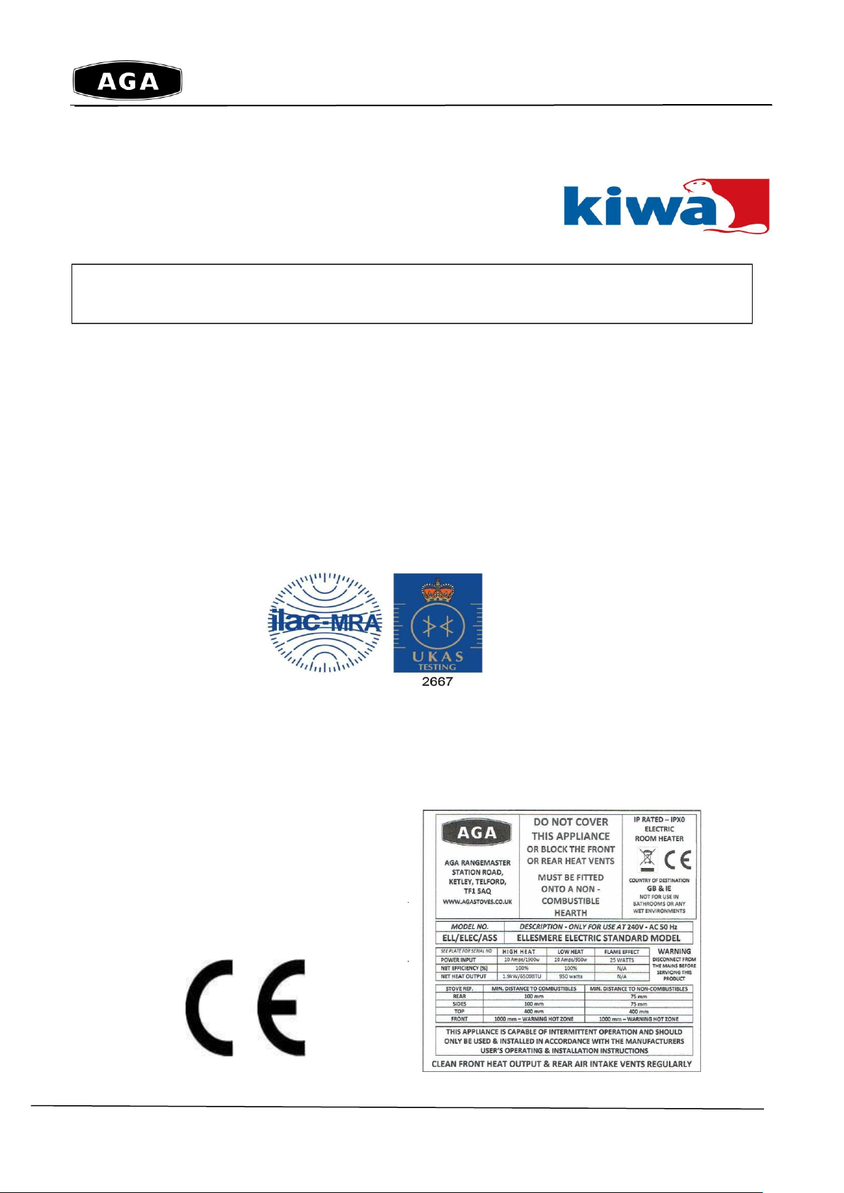
CONFORMITY WITH DIRECTIVES
This stove conforms to all relevant European
Directives and is fully CE Compliant
CE Plate - Fixed to the Rear of the Stove (Not to Scale)
This AGA Electric Stove has been fully tested and CE Approved in the UK by KIWA
Blackwood Compliance Laboratories, a leading European Test Agency
Electrical Safety Test Certificate
Page 6
Page 7

AGA Ellesmere Electric Standard Stove
Installation & User Manual
IMPORTANT INSTRUCTIONS
1. Read all instructions before installing or using this heater.
2. DO NOT COVER THIS STOVE IN ANY WAY WHAT SO EVER
3. THIS STOVE MUST BE FITTED ONTO A NON COMBUSTIBLE HEARTH, WHICH
EXTENDS 225MM PAST THE FRONT OF THE STOVE &100MM TO THE REAR.
4. DO NOT BLOCK THE COOL AIR INLET AT THE REAR OR THE HOT AIR OUTLET
AT THE FRONT
5. ENSURE NO FOREIGN BODIES BLOCK THE COOL AIR INLET AT THE REAR
OR THE HOT AIR OUTLET AT THE FRONT OF THIS STOVE (SUCH AS PET
HAIRS CARPET FLUFF ETC) REGULARLY CLEAN ANY DUST, FIBRES OR
DEBRIS FROM THESE VENTS AT THE FRONT AND BACK OF THE STOVE
6. Keep combustible materials, such as furniture, pillows, bedding, papers, clothes and curtains
at least 1000mm (39 inches) from the front, sides and rear of the heater.
7. Ensure the rear mounting bracket is fitted before opening the door, otherwise the stove could
tip forward
8. Always unplug (3 pin plug) heater when not in use.
9. Do not operate the fireplace if it has a damaged cord or plug, after it has malfunctioned, or if
the unit has been dropped or damaged in any way.
10. Do not use the heater outdoors.
11. Do not run the cord under carpeting. Do not cover the cord with throw rugs, runners or
anything else. Arrange the cord away from traffic areas where it could cause a tripping
hazard.
12. To disconnect the heater, turn the controls to "OFF" before removing the plug from the outlet.
13. Do not insert or allow foreign objects to enter any ventilation or exhaust opening, as this may
cause an electric shock, fire or damage to the heater.
14. To prevent a possible fire, do not block air intakes in any way.
15. A heater has hot and arcing or sparking parts inside. Do not use it in areas where
petrol/gasoline, paint or flammable liquids are used or stored.
16. Use this heater only as described in this manual. Any other use not recommended by the
manufacturer may cause fire, electric shock or injury.
17. Avoid the use of an extension cord, the extension cord could overheat and cause a fire. This
heater is not to be used with an extension cord.
18. Always use properly grounded fused and polarized outlets.
19. Always use ground fault protection where it is required by electrical codes.
20. Always disconnect the power before performing any cleaning, maintenance or relocation of
the heater.
21. To prevent a possible fire, do not burn wood or other materials in this heater.
22. To prevent electric shock or fire, always use a certified electrician, should new circuits or
outlets be required.
23. When transporting or storing the heater, keep it in a dry place, free from excessive vibration.
24. This appliance should not be modified under any circumstances.
25. Packaging material should be kept away from children and be disposed of in a safe manner.
Plastic bags are not toys and should be kept away from children and infants.
Page 7
Page 8
AGA Ellesmere Electric Standard Stove
Installation & User Manual
DO’s
DO INSTALL THIS STOVE ONTO A NON COMBUSTIBLE HEARTH, WHICH EXTENDS
225MM PAST THE FRONT OF THE STOVE.
CLEAN THE INLET & OUTLET VENTS REGULARLY AT LEAST ONCE A WEEK
DEPENDING ON OPERATING CONDITIONS TO REMOVE ANY DUST, FIBRES OR
DEBRIS (SUCH AS PET HAIRS & CARPET FLUFF ETC)
Always install the heater in accordance with this guide. If in doubt obtain expert advice
Always make sure the electrical socket is accessible and located adjacent to, but not
above the heater.
Always disconnect the heater from the electrical supply before moving it, or carrying out
cleaning, maintenance.
Always make sure the heater is firmly secured to prevent it from being tipped over,
using the rear fixing bracket
Always use a fireguard when young children and infirm persons can come into contact
with the heater.
DON’Ts
NEVER COVER THIS STOVE IN ANY WAY WHAT SO EVER
DON’Ts
NEVER BLOCK THE COOL AIR INLET AT THE REAR OR THE HOT AIR OUTLET
AT THE FRONT
DON’Ts
NEVER ALLOW FOREIGN OBJECTS TO BLOCK THE COOL AIR INLET AT THE
REAR OR THE HOT AIR OUTLET AT THE FRONT OF THIS STOVE (SUCH AS PET
HAIRS & CARPET FLUFF ETC)
DON’Ts
Never leave children unsupervised in a room where the heater is ON and unguarded.
Never obstruct or cover the fan outlet or force items into heater openings.
Never install or use the heater anywhere where water is in use, i.e. Bathroom, Kitchens,
Shower Rooms, Swimming Pool etc.
Never use aerosols or steam cleaners on or around the heater.
Never route the mains supply cable under carpet etc.
Never install the heater close to curtains or combustible materials.
Never use the heater to dry clothes etc.
Never sit or stand on the heater.
Never use with a timer or any other device that switches the fire on automatically.
26. Do not use this heater in small rooms when they are occupied by persons not capable of
leaving the room on their own, unless constant supervision is provided.
27. If the glass is damaged, do not use the heater in order to avoid a hazard.
28. Do not leave children unsupervised when heater is turned on.
29. CAUTION Some parts of this product can become very hot and cause burns. Particular
attention has to be given where children and vulnerable people are present.
30. This appliance can be used by children aged from 8 years and above and persons with
reduced physical, sensory or mental capabilities or lack of experience and knowledge if they
have been given supervision or instruction concerning use of the appliance in a safe way and
understand the hazards involved. Children should not play with the appliance. Cleaning and
user maintenance shall not be made by children without supervision.
The DO’s & DON’Ts
Page 8
Page 9
AGA Ellesmere Electric Standard Stove
Installation & User Manual
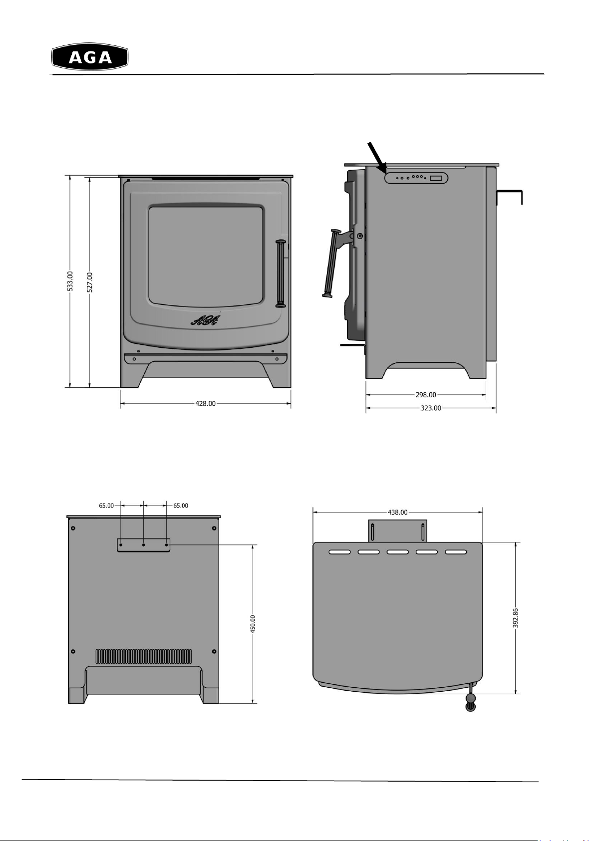
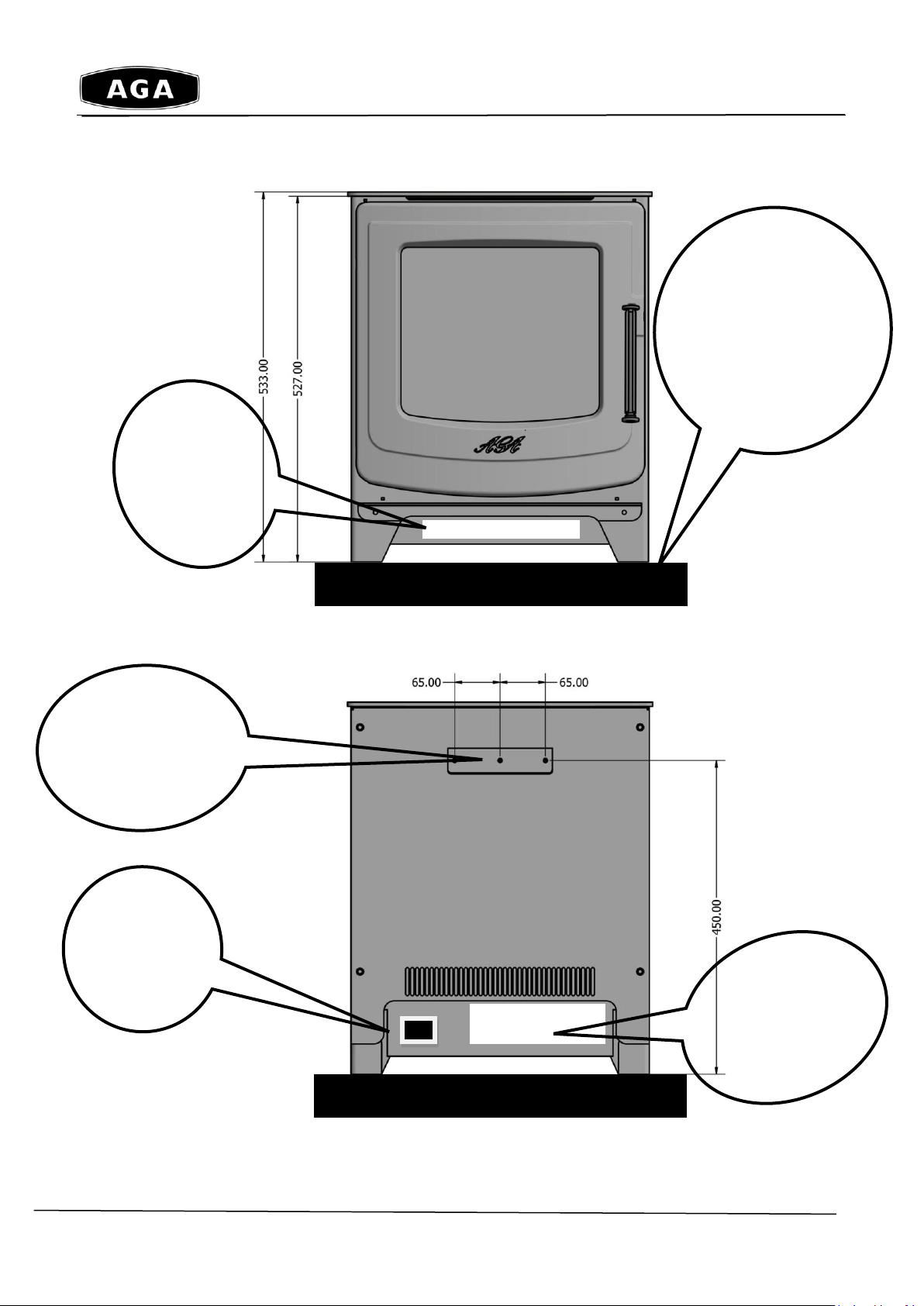
STOVE DIMENSIONS
Manual Controls and the ON/OFF Switch
Front View Right Hand Side View
Rear View Top View
Drawings are Not to Scale
Page 9
Page 10
AGA Ellesmere Electric Standard Stove
Installation & User Manual
Hearth Must
Extend
225mm to
the front of
the Stove
Hearth
Must Extend
100mm to
the rear of
the Stove
Must be
Installed onto a
Non-
Combustible
12mm thick
Hearth
INSTALLATION MUST BE ONTO A NON-COMBUSTIBLE HEARTH
(Hearth is shown as thick Black Line below)
Drawing Not to Scale
============ ====
225mm 100mm
This stove must be fitted on to a Non Combustible Hearth with a minimum
thickness of 12mm, which extends:
225mm from the front of the door of the stove
Minimum of 100mm from the rear of the stove
Minimum of 75mm either side of the stove
Page 10
Page 11
AGA Ellesmere Electric Standard Stove
Installation & User Manual
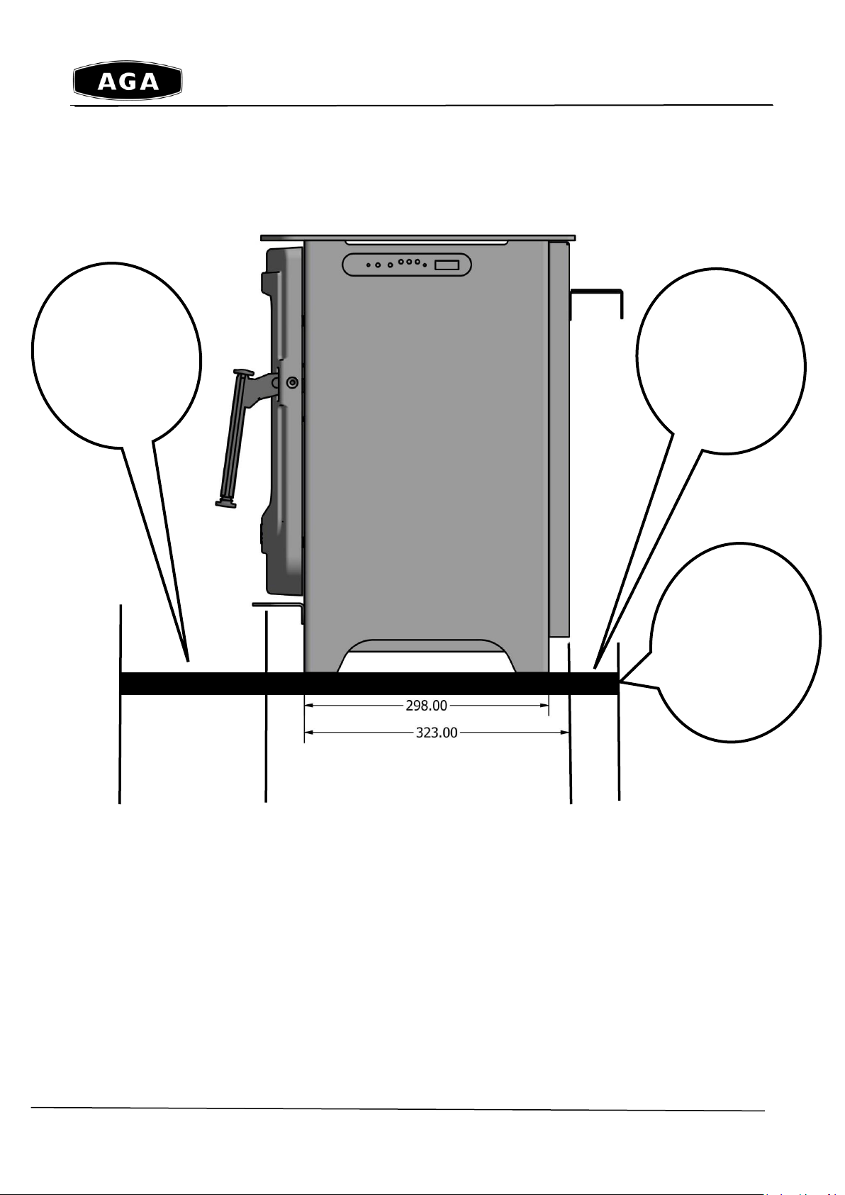
Rear View - Cool Air Intake Grill shown in white box above, this must be kept clear of any
foreign objects such as Pet Hairs and Carpet Fluff, this must be regularly cleaned so the
vents are clear of foreign objects, such as dust, debris and fibres.
Mains
Socket
Plugs in
Here
Rear Cool Air
Inlet Vent
KEEP CLEAR
Hot Air
Output
Vent
KEEP
Must be Installed
onto a
Non-Combustible
12mm thick
Hearth
Rear Wall
Fixing Bracket
Must be
Installed
DO NOT COVER THIS STOVE – this will void the warranty
Above Front View - Hot Air Output Grill must be kept clear– shown in white box above
Page 11
Page 12

AGA Ellesmere Electric Standard Stove
Installation & User Manual
WARNING – ELECTRIC SHOCK HAZARD
It is the customers responsibility to contact a qualified
electrical installer to make sure the electrical installation
is adequate and in conformance with the regulations.
Take special care when cutting holes in walls or floor.
Electrical wires may be behind the wall or floor covering
and could cause an electrical shock if you touch them.
Locate any electrical circuits that could be affected by the
installation of this product and disconnect power circuit
WARNING: THIS APPLIANCE MUST BE EARTHED.
DO NOT use an extension lead with this appliance.
The appliance is designed for the voltage stated on the
CE data plate.
Recommended but not mandatory to fit an individual Residual
Current Device (RCD) to the ring main supply circuit to this stove.
Please Hand this Manual to the customer/User for retention and
future instructions in the safe operation of the appliance.
UNPACKING AND TESTING APPLIANCE
Carefully remove the appliance from the box.
Prior to installing the appliance, test to make sure the appliance operates properly by
plugging the power supply cord in the socket on the back of the stove and then directly into a
240 Volt wall socket (not an extension lead or a multi-plug in a wall socket)
Test all aspects of its operation (manual switches, remote and heater) to make sure all
components are operating correctly.
As with most electronic devices, your new electric stove has been designed to operate at
temperatures between 5℃ (41℉) and 35℃ (95℉). During the cold winter months, allow the
stove to reach a minimum room temperature of 5℃ before turning it on.
NOTE: There may be a trace of odour during the first time you use this stove. This is
caused from the paint finish curing, if the smell is strong open the windows and
operate the stove on the full heat setting for 30 to 45 minutes to allow the paint to cure,
children, the elderly or pets should not be allowed into the room during this period
Page 12
Page 13

AGA Ellesmere Electric Standard Stove
Installation & User Manual
Item 1 - Log Media Pack includes the following:
11 x Piece Log set – various sizes
Large bag of Glass Amber Bead Embers
Small bag of White Vermiculite Chippings
Small bag of Black Vermiculite Chippings
All of the items are packed into this cardboard box
In the box is
Item 1 - Log Media Pack
Item 2 - Remote Control
Item 3 - 2 x AAA Batteries
Item 4 - Power Cable
Item 3 - Batteries
WHAT COMES WITH THE STOVE
1 - Media Pack consisting of Logs and Embers – please refer to the Media Section
2 - Remote Control
3 - 2 x AAA Batteries - packed separately
4 - Power Cord with 3 pin sealed plug fitted – 10 AMP fuse fitted
5 - Wall Fixing Bracket – please note this is already fitted to the rear of the stove
Item 2 – Remote Control
Item 3 – Power Code
Page 13
Page 14

AGA Ellesmere Electric Standard Stove
Installation & User Manual
Step 1 - Drill x 3 holes - 7mm diameter x 40mm deep to suit brown masonry
wall plug. - 65mm centres 450mm from base level into the rear wall
Step 2 - Insert 3 X 30mm Long Brown Rawplugs into the 3 drilled holes in
the back wall (marked as item 1)
FITTING THE REAR WALL FIXING BRACKET
This bracket must be fitted to the rear of the stove to ensure that the stove will not tip forward
when the stove door is opened
12mm thick
Non-Combustible
Hearth
Back Wall,
which the
Stove
Bracket will
be Mounted
onto
Page 14
Page 15

AGA Ellesmere Electric Standard Stove
Installation & User Manual
Step 3 - Fix wall bracket (item 3) with 3 x no. M5 x 25mm long posi drive
screws (item 4) as shown Note orientation of the bracket
Step 4 - Offer up the fire to the wall bracket so the two brackets align fit the
2x no. M5 x 20mm long cap screw supplied into bracket adjust distance to
wall to suit (max 102.5mm, min 65mm) tighten screws
Page 15
Page 16

AGA Ellesmere Electric Standard Stove
Installation & User Manual
Congratulations the rear fixing bracket is now complete and the stove is securely fixed to the rear
wall. Now you can open the door without the possibility of the stove tipping forward and lay your log
arrangement
Please note the arrows on the drawing so COOL air enters at the rear of the stove then HOT air
comes out from the front of the stove below the door
Please ensure the stove is fitted onto a non-combustible hearth as described earlier in this manual
Please ensure there is 100 mill gap at the rear so COOL air from the room can enter into the rear of
the stove without any restriction
IMPORTANT - Please make sure the front Hot Air outlet and the rear Cool Air inlet are regularly
cleaned so no foreign matters such as pet hairs and carpet fluff can block these 2 vents
NEVER COVER THIS STOVE – THIS COULD CAUSE A FIRE
Now just plug in your stove using the 3 pin plug lead provided into the female plug socket at the
rear of the stove. Please note the 3 pin Plug must be plugged into a wall mounted three pin
socket (which is part of your 13 amp ring main) not an extension lead or a multi plug in the wall
HOT Air Out
COOL Air In
Page 16
Page 17

AGA Ellesmere Electric Standard Stove
Installation & User Manual
Amber Glass Bead Embers
Black & White Vermiculite Chippings
11 – Piece Log Set
SETTING UP THE LOG SET & MEDIA
Your Stove is supplied with 11-piece-log, Amber Glass beads and Black and White
Vermiculite chippings.
Large Bag of Amber Glass Bead Embers
to be placed onto LED light base of the
stove
Small bag of White and Black Vermiculite chippings to
place over the logs and Amber glass beads to enhance
the real log burning feature
Page 17
Page 18

AGA Ellesmere Electric Standard Stove
Installation & User Manual
Stove with the base lights and the rear flame effect turned
on - only using the Yellow light option
Step 1 - Now you are ready to place the media and logs into your stove
Firstly pour the bag of amber glass beads onto the glass base plate which will
allow the light from the base lights to diffuse and glow
LOG SET - SAMPLE LAYOUT
Page 18
Page 19

AGA Ellesmere Electric Standard Stove
Installation & User Manual
Step 2 - You can lay the logs in what ever pattern or design you wish, there
are 11 x logs of various sizes (length and thickness) so from the 11 x logs
select the ones you wish to assemble into the stove and arrange them in a
manner that suits you.
Also included are the black and white vermiculite chippings you can just
sprinkle these over the top of the logs for that final log burner effect
Now just clean the door glass inside and out with a damp cloth, then close
the door. The door only needs to be reopened if you wish to change the
log arrangement. So for safety reasons keep the door closed
You probably won’t want to use all 11 x logs in the fire bed at the same time
but keep the extra ones safe as this gives you the option to change the log
bed design when you wish
Now sit back and enjoy
Page 19
Page 20

AGA Ellesmere Electric Standard Stove
Installation & User Manual
ICON
DESCRIPTION OF THE FUNCTION – FULLY DETAILED OVERLEAF
Red in Colour – this is the Main ON/OFF button for the stove, this will turn on the LED lights and
the Heater
This button operates the LED lights in the base and the rear flame effect turning them on or off, so
you can have the heater on, but the lights off
This Flame icon appears on the remote screen to show the flame effect is working
This operates the RED coloured LEDs in the base and the red colour in the flame effect in the
back of the stove, there are 3 x levels of brightness, High, Medium and Low – each time you
press the button the brightness will adjust on the 4th press of the button this light colour will turn
off. You can operate all 3 lights together or just one colour or 2 colours together.
This operates the YELLOW coloured LEDs in the base and the red colour in the flame effect in
the back of the stove, there are 3 x levels of brightness, High, Medium and Low – each time you
press the button the brightness will adjust on the 4th press of the button this light colour will turn
off. You can operate all 3 lights together or just one colour or 2 colours together.
This operates the BLUE coloured LEDs in the base and the red colour in the flame effect in the
back of the stove, there are 3 x levels of brightness, High, Medium and Low – each time you
press the button the brightness will adjust on the 4th press of the button this light colour will turn
off. You can operate all 3 lights together or just one colour or 2 colours together.
This button operates the top light colours. There are 16 shades of colour varying from red,
green, blue, violet, purple & yellow. If you want you can just have the down lights on without the
flame effect
This is the Fan Heater Button and operates the Heater unit turning it ON/OFF and between the
high and low settings
The Remote control screen displays this icon which means the stove is operating on its High heat
setting which is 1900W
The Remote control screen displays this icon which means the stove is operating on its Low heat
setting which is 950W
Press this button to adjust the temperature setting between 7℃ and 30 ℃ The buzzer beeps
when the remote key is pressed;
This is the Shift Key button to adjust the settings
OPERATING YOUR STOVE
Understanding the Icons on the Remote Control
Page 20
Page 21

AGA Ellesmere Electric Standard Stove
Installation & User Manual
ICON
DESCRIPTION OF THE FUNCTION – FULLY DETAILED OVERLEAF
This button operates the Timing Parameter Settings
This Button operates the Open Window function, this automatically adjusts the room temperature
when set up
This button operates Setting up the Timer Function on the stove
Time Table indicator for Setting up the Heater Parameter on the Remote Control Screen
Press this button to turn ON/OFF and adjust the Fan Heater output HIGH/LOW
Press this button to turn ON/OFF and adjust the brightness of the LED base lights and the rear
flame effect. N.B All 3 light colours operate together only from this button
Side Screen on stove light is RED indicates heater is on the High Heat setting of 1900W
Side Screen on stove light is BLUE indicates heater is on the Low Heat setting of 950W
Side Screen on stove light is YELLOW indicates Open Window Function is on
Side Screen on stove light is GREEN indicates Timer Function is on
This touch panel is located on the top
right hand side of the stove
Understanding the Icons on the side of the stove for Manual Operation
Page 21
Page 22

AGA Ellesmere Electric Standard Stove
Installation & User Manual
1
TURNING THE HEATER ON/OFF ONLY – LOW HEAT / HIGH HEAT
Press the button/key on the touch pad. When pressed for the first time,the heater will work at the
High Heat Setting of 1900W, the indicator panel lights up RED.
Press for the second time, the heater reduces to the Low Heat setting of 950W,the indicator panel
lights up BLUE. Press for the third time, the heating element turns off, the indicator panel light
extinguishes.
Note: After the heating elements are turned on manually, the heating elements will work but are not
controlled by the temperature thermostat sensor which is located inside the stove.
2
FLAME EFFECT ONLY – BLUE, RED & YELLOW LED LIGHT OPTIONS
Press key button/key on the touch pad. When pressed for the first time, the bottom base LED
lights and rear flame will light up on their highest brightness setting, this automatically brings on all 3 x
light colours Blue, Red & Yellow. Press for the second time, the base LED lights and rear flame are set to
their medium brightness. Press for the third time, the base LED lights and rear flame will be in its lowest
brightness setting. Press for the fourth time, the base LED lights and rear flame goes out.
RED LIGHTS - for Real Wood / Coal Flame effect
YELLOW LIGHTS - for Real Wood Flame effect
BLUE LIGHTS - usually used for the ICE mood effect
When used in remote control mode you can mix all of the 3 lights and brightness’s together or just have
one and/or two light colour(s) on independently to set the mood you require in the room
MANUALLY OPERATING THE STOVE - INSTRUCTIONS
This touch pad is located on the right hand side of the stove at the top
Page 22
Page 23

AGA Ellesmere Electric Standard Stove
Installation & User Manual
1
TURNING ON THE STOVE WITH THE REMOTE – HEAT & LIGHTS
Press the remote control’s key , the remote screen turns on, the bottom base LED lights
and rear flame ignites and the flame icon ap pears on the screen of the remote control.
The Week, Time (24h system), and Temperature setting are displayed normally. Press it
again, the screen of the remote control will turn off. To turn on the heat press the heater
button please refer to point 5 for full details
2
JUST TURNING ON THE LED LIGHTS FOR THE FLAME EFFECT IN THE BASE & REAR
Once the stove has been turned on as described in 1 above, you can just operate turning
On/Off the bottom base LED lights and rear flame using the button on the remote
control.
REMOTE CONTROL OPERATION
1
2
3
Page 23
Page 24

AGA Ellesmere Electric Standard Stove
Installation & User Manual
3
TURNING ON THE INDIVIDUAL LIGHTS – BASE & REAR FLAME
The 3 x colours can be adjusted in brightness from Low, Medium & High then OFF
independently as follows by just single pressing the icon button on the remote below:
Press (1) to adjust the red flame. The buzzer beeps once when the key is pressed;
Press (2) to adjust the yellow flame. The buzzer beeps once when the key is pressed;
Press (3) to adjust the blue flame. The buzzer beeps once when the key is pressed;
You can mix all of the 3 lights and brightness’s you require together or just have one and/or two light
colour(s) on independently to set the mood you require in the room by just pressing the 3 coloured
flame buttons on the remote control
4
TURNING ON/OFF & ADJUSTING THE COLOURS OF THE DOWN LIGHTS
Press the button to turn on, turn off and adjust the top light colors. The buzzer beeps
once when the key is pressed; There are 16 shades of colour varying from red, green, blue,
violet, purple & yellow. If you want you can just have the down lights on without the flame
effect
5.
TURNING ON THE HEATER ONLY – HIGH & LOW HEAT
Press the Heating key . When pressed for the first time, the heating elements works at
the High Heat setting of 1900W, the LCD screen displays , the indicator on the stove
lights red. Press a second time, the heating elements reduces down to the Low Heat Setting of
950W, the LCD screen displays , the indicator on the stove lights blue. Press a third
time and the heating elements turns off, the LCD screen does not display the function icon, the
indicator on the stove goes off. The buzzer beeps once when the key is pressed;
Note: in case the heating elements are turned on by remote control, whether the heating
elements work or not depends on the temperature setting and ambient temperature. They
work only when the temperature setting is above the ambient temperature.
Page 24
Page 25

AGA Ellesmere Electric Standard Stove
Installation & User Manual
6
AJUSTING THE TEMPERATURE SETTING
Press key to adjust the temperature setting between 7℃ and 30 ℃.
The buzzer beeps when the key is pressed;
7. SETTING UP THE REMOTE CONTROL TIME & DAY FUNCTIONS
Press shift key . Press once, the corresponding figure flashes. Press
now to set current time and week. The buzzer does not beep when the key is pressed
8.
SETTING THE TIMER CONTROL
Press timing parameter setting key“ .” Press for the first time and the LCD screen
displays to indicate Monday. Now the temperature setting flashes, press “ ” “ ”
to set the timing temperature for Monday, press key “ ” to confirm and then press
“ ” “ ” the time setting for timing. The displayed time parameter is “00-23.” Press
“ ” to set the current operating state of timing function; indicates that the timing is
on currently and the control temperature is the temperature setting, indicates that the
timing is on currently and the control temperature is the temperature setting minus 3 ℃, No
display indicates timing is off currently and the heating elements do not work. Corresponding
point flashes when setting. Press for the second time, it displays , set the parameters
for Tuesday. Press for the 7th time and it displays . Press for the 8th time and it exits and
recovers to the current week day;
Page 25
Page 26

AGA Ellesmere Electric Standard Stove
Installation & User Manual
9.
SETTING UP THE TIMING PARAMETER
Press “ .” Press for the first time and the timing function turns on, the LCD screen
displays , the stove’s indicator lights green. Press again to turn off, icon
on the LCD screen goes off. After the timing function is turned on, it works according
the parameter settings. The LCD screen
lights up according to corresponding parameter settings;
Note: when the time, week and timing parameters are changed, you need to switch on-off the
timing key to transfer the timing parameters to the machine. After the machine has received
them correctly, the buzzer will beep once.
10.
SETTING UP THE OPEN WINDOW CONTROL
Press“ ”. Press once to turn on the Open Window function, the LCD screen displays
icon , the indicator on the stove lights yellow. Press again to turn it off, the LCD
screen does not display icon and the indicator on the stove goes off. The buzzer
beeps when the key is pressed;
After the Open Window function is turned on, the program firstly detects if the heating
function is turned on. If it is turned on, the program will save the current ambient temperature
value and detects the ambient temperature change once per 12 minutes. When the decrease
in the ambient temperature detected within 30 minutes exceeds 4℃, the program will deem
that the window is open and stop heating, and the Open Window indicator on the stove
will flash rapidly. After it has stopped heating for 70 minutes, the program starts to detect if the
window is closed, and the indicator flashes slowly. It heats for 6 minutes every 30
minutes (position H2). If the temperature rise is more than 2℃, the window is considered as
closed, and the indicator ℃ stops flashing.
Page 26
Page 27

AGA Ellesmere Electric Standard Stove
Installation & User Manual
STOVE RESET SEQUENCE
1) Unplug the Stove from the wall socket
2) Switch the unit OFF on the rocker switch on the side of the stove
3) Turn the on/off rocker switch to ON
4) Using the remote only turn the display ON
5) Does it work?
6) Turn the heater on to the low setting
7) Does it work?
8) Turn the heater on to the high setting
9) Does it work?
CARE AND MAINTENANCE
1. Switch off and unplug from the power supply before cleaning.
2. Using a soft, moist cloth, with or without a mild soap solution, carefully clean the exterior surface
of the products.
CAUTION: Unplug from the mains electrical supply and allow the product to completely cool
before handling or cleaning it.
3. Do not allow water or other liquids to run into the interior of the product, as this could create a
fire and/or electrical hazard.
4. We also recommend the periodic cleaning of this appliance by lightly running a vacuum cleaner
nozzle over the guards to remove any dust or dirt that may have accumulated inside or on the
unit.
5. VERY IMPORTANT - REGULARLY CLEAN THE COOL AIR INLET VENT AT
THE BOTTOM REAR OF THE STOVE AND THE HOT AIR OUTPUT VENT AT
THE BOTTOM FRONT OF THE STOVE OF ANY FOREIGN MATTERS SUCH
AS PET HAIRS, CARPET FLUFF, DUST, DEBRIS OR FIBRES
CAUTION: Do not use harsh detergents, chemical cleaners or solvents as they may damage the
surface finish of the plastic components.
Page 27
Page 28

AGA Ellesmere Electric Standard Stove
Installation & User Manual
NO
PART NUMBER
DESCRIPTION
QTY.
Ellesmere ECE Standard
Ellesmere ECE Wide
N/A
1
TOP PANEL
1
2
602065D
BLOWER AND HEATER ASSEMBLY
1
3
601094F
CIRCUIT BOARD
1
4
FIREPLACE BOX
1
5
10104010
SWITCH
1
6
601035
CONTROL PANEL
1
7
301506
REMOTE RECEIVER
1
8
601141
601141
FLAME LED STRIP
1/0/1
9
601142
0/1/0
10
10702244
10702246
10702249
BOTTOM GLASS
1
11
10125025
CANOPY LIGHT
1
12
10101221C
FLAME MOTOR
2
13
3215505
3216505
3217505
FLICKER ASSEMBLY
2
14
10702245
10702247
10702248
BACK GLASS
1
15
601136B
601136B
TRAY LED STRIP
1/0/2
16
601137B
0/1/0
17
10105203
REMOTE CONTROL
1
ENVIRONMENTAL PROTECTION
RECYCLING
This symbol is known as the 'Crossed-out Wheelie Bin Symbol'. When this
symbol is marked on a product or battery, it means that it should not be
disposed of with your general household waste. Some chemicals contained
within electrical/electronic products or batteries can be harmful to health and
the environment.
Only dispose of electrical/electronic/battery items in separate collection schemes,
which cater for the recovery and recycling of materials contained within. Your
co-operation is vital to ensure the success of these schemes and for the
protection of the environment.
REPLACEMENT PARTS FOR THE ELECTRIC FIRE BOX ONLY
.
Page 28
Page 29

AGA Ellesmere Electric Standard Stove
Installation & User Manual
Reference
Qty
Description
Part Number
1
A5E Main Body
10500
2 A5E Rear Heat Shield
10501
3
A5 Cast Door
10502
4 Wall Mounting Bracket 1
10503
5 Wall Mounting Bracket 2
10504
6 EC5 Electric Firebox Assembly
10505
7
Front Ash Lip
10506
8 & 9 6 M5 X 15 CAP SCREW
10507
10 1 Handle Assembly
10508
11
1
M6 CSK x 30mm Screw Handle Pivot
10509
12 M6 CSK x 25mm Screw
10510
13 A5 Glass Gasket
10511
14 A5 Standard Electric AGA Glass
10512
15, 16 & 17
4
Glass Clips & Fixing Screws & Washers
10513
18 & 19
1
Handle Roller and Fixing Screw
10514
20 2 Door Hinge Pins
10515
EXPLODED VIEW & PARTS LIST
Page 29
Page 30

AGA Ellesmere Electric Standard Stove
Installation & User Manual
PROBLEM
POSSIBLE CAUSE
SOLUTION
Dim or no flame
Flame LED’s are burnt out
Inspect the LED’s and replace
them if necessary
Back black cloth is falling off
and roll the flicker
Change a new flicker and back
black cloth
Ember bed is not
glowing or dimming
Ember LED’s are burnt out
Inspect the ember bed LED’s and
replace them if necessary
Appliance turns off
and will not turn on
Appliance has overheated
and safety device has caused
the thermal switch to
disconnect
Turn off the main switch, allow
appliance to cool for 10 minutes,
then turn it on
House circuit breaker has
tripped
Reset house circuit breaker
Appliance’s fuse has blown
Replace the fuse
Appliance will not
come on when switch
is flipped to ON
Appliance is not plugged into
an electrical outlet
Check plug and plug in
Appliance has overheated
and safety device has caused
the thermal switch to
disconnect
Turn off the main switch, allow
appliance to cool for 10 minutes,
then turn on
Circuit board is burnt out
Inspect the circuit board and
replace if necessary
No warm air coming
out of appliance
Heater is burnt out
Inspect the burner and heater
assembly and replace if necessary
Flame sputters
Flame motor is defective
Call a qualified service technician
and replace flame motor
Remote Control does
not work
Low batteries
Unit switch in “O” position
Replace AAA batteries in remote
control
Turn the switch in “I” position
Flame is fixed
Wiring may be loose or the
flame motor may be defective
TROUBLE SHOOTING
Page 30
Page 31

AGA Ellesmere Electric Standard Stove
Installation & User Manual
Date
Dealer
Name
Service Technician
Name
Service Performed
Special Concerns
SERVICE HISTORY
This heater must be serviced annually depending on usage.
NOTES:
Page 31
Page 32

AGA Ellesmere Electric Standard Stove
Installation & User Manual
AGA FREESTANDING ELECTRIC STOVE – 2 YEAR EXTENDED WARRANTY
If you have purchased your stove from an authorised stockist within our Retailer Network, then automatically
your product will carry an extended 2 year warranty. You do not need to register your stove for the warranty,
but you need to retain your invoice as proof of purchase, as you will need this to make a warranty claim. So
please keep the purchase invoice/receipt safe, you will also require the serial number of the stove which is
on an aluminum plate above the bottom door hinge, so open the door and you will see it. This allows us to
trace the date the stove was manufactured and which retailer it was sold to. Any warranty claims have to be
dealt with by the retailer you purchased the stove from, the retailer will then contact AGA to deal with any
warranty claims
Any product purchased outside of our Premium Retailer Network will carry a standard 12 month,
non-extendable warranty.
It is a condition of the Extended Warranty that the installation complies with relevant Building Regulations
and the rules in force, and is carried out by a suitably trained and qualified/competent person and the
freestanding stove is installed as detailed in the installation and operating manual, ensuring the stove has
ample ventilation completely around the stove.
This warranty is not transferable and is extended only to, and solely for, the benefit of the original purchaser
of the stove. Please retain your dated sales invoice/receipt as a proof of purchase. During your extended
warranty period, only genuine spare parts must be used in the servicing and maintenance of your stove,
these spare parts can be ordered via the Premium Retailer directly. Consumable items such as glass, paint,
screens, door rope seals, bulbs, LED light boards, ceramic/plaster fuel effects, remote controls, glass
beads and batteries which are either subject to normal wear and tear or parts that require replacement in
connection with normal maintenance and are not covered, either by the original or the Extended Warranty.
Should you experience problems with your stove, any claim must be submitted to
warranty@agastoves.org.uk with details of the supplying retailer and installation partner.
Warranty Exclusions and Limitations
No Warranty is extended to consumable service parts. Repair or replacement of parts which are subject to
normal wear and tear during the warranty period or parts that will require replacement in connection with
normal maintenance. Such parts include but are not limited to glass, screens, bulbs, LED boards, ceramic
fuel effects, glass beads and batteries.
Additional Advisory Information
Please do not cover this stove in anyway what so ever with anything as this could cause damage to the
stove and void any warranty
You must fit the stove in accordance with the manufacturer’s instructions and regularly clean any dust, fibres
or debris (Pet hairs & Carpet Fluff) from the fan heater inlet and outlet as this could cause damage or
become a fire risk. This stove must be installed on a non-combustible hearth with the correct clearance
around it so air flow can move around the stove freely as detailed in the installation manual
Page 32
Page 33

AGA Ellesmere Electric Standard Stove
Installation & User Manual
The Extended Warranty does not cover:
a) In normal usage the paint finish of your Stove may change colour slightly. As these circumstances are
considered normal, they are not covered by the warranty.
b) Enamelled components where these parts are subjected to abnormally high temperatures, chemical
abrasion or thermal shocks, resulting in chipping, cracking, bubbling or discolouration and crazing of the
enamelled finish.
c) Damage resulting from installation and usage where the appliance has not been installed or used in
accordance with the Stoves installation and operation instructions, or if the installation does not conform to
local building, fire and safety regulations.
d) Defects or faults caused by specific local conditions such as draught problems, water damage and
condensation (including the remote control unit)
e) Damage caused by unauthorised modifications, use or repair.
f) Damage or defects caused by the product being stored in a damp, unheated environment.
g) Consequential loss (to the extent permitted by law) relating to other associated products that have not
been supplied by AGA Stoves.
h) Consequential loss (to the extent permitted by law) related to decorations, furnishings or other household
assets.
i) Delivery to/or return transport costs, Removal and re-installation costs. or any labour cost to fit parts
Repaired or replaced products are covered only for the remainder of the original warranty period.
If you should ever wish to make a warranty claim because of a product fault or defect, you must inform us
within a reasonable amount of time, this is within 14 days from the date on which the fault or defect first
became apparent. If the product fault or defect is notified after 14 days from the date on which the fault or
defect became apparent, we cannot accept any liability for events or issues which arise after the 14 day
period or which are caused or increased by the lack of notification which therefore prevented action being
taken to restrict or eliminate any consequences arising from the fault or defect at an earlier date.
In the event of a product fault occurring during the warranty period, we will send the appropriate components
or goods necessary to rectify the fault, free of charge. but this does not cover any labour cost to fit them.
Nothing in the Extended Warranty shall make AGA Stoves or their partners liable for any or special,
incidental or consequential damages, injury to persons or property, or any other consequential loss beyond
the consumer’s statutory rights. The liability on AGA Stoves total liability extends only to the purchase price
paid for the goods by the Premium Retailer, except where such a limitation is prohibited by statute. AGA
Stoves, in the event of a warranty claim, reserve the right to either replace the goods in question or to refund
the purchase price of the goods as paid by the Premium Retailer.
The Extended Warranty does not affect your statutory rights.
The above warranty terms and conditions came into effect on 1st January 2013 and are applicable for all
relevant products purchased after this date. Please note: This warranty is applicable for purchases within the
United Kingdom (mainland only).
Page 33
Page 34

AGA Ellesmere Electric Standard Stove
Installation & User Manual
With AGA Rangemaster’s Policy of Continuous Product Improvement, the Company reserves
the right to change specifications and make modifications to the appliance described and
illustrated at any time
AGA Rangemaster
Station Road, Ketley
Telford, Shropshire
TF1 5AQ
United Kingdom
www.agastoves.co.uk
This Stove has been fully CE Tested, Approved
& Manufactured in the UK
This stove conforms to all relevant European Directives
Page 34
 Loading...