

Page 1

03/08 EINS 513307
Remember, when replacing a part on this appliance, use only spare parts that you can be assured
conform to the safety and performance specification that we require. Do not use reconditioned or copy
parts that have not been clearly authorized by Aga-Ranges.
PLEASE READ THESE INSTRUCTIONS BEFORE USING THIS APPLIANCE
IMPORTANT : SAVE OWNERS MANUAL FOR THE LOCAL INSPECTORS USE
CUSTOMER: KEEP THESE INSTRUCTIONS FOR FUTURE REFERENCE
Comprising
Installation & Users
Instructions
AGA ELECTRIC RANGE (EC LM - 2
OVEN & EE LM - 4 OVEN) - OWNERS
MANUAL
FOR USE IN USA/CANADA
Page 2

2
CONTENTS
SECTION PAGE
INSTALLATION 3
GENERAL NOTES 4
INSTALLATION 4
APPLIANCE DIMENSIONS 5-6
ELECTRICAL 7
INSTRUCTIONS 7
ELECTRICAL TEST PROCEDURE 7
WIRING DIAGRAM 8
USERS GUIDE 9
SAFETY PRECAUTIONS 10-11
RANGE ACCESORIES 12
HEAT INDICATOR 12
THERMOSTAT CONTROL 12
SERVICING 13
OPERATING YOUR AGA 13
FITTING OF OVEN SHELVES 14
REMOVAL OF OVEN SHELVES 15
CLEANING & CARING FOR YOUR AGA 16
GUIDE TO AGACOOKING 16
Page 3

Installation
Section
3
CAUTION:
THIS UNIT IS HEAVY, PROPER EQUIPMENT AND ADEQUATE
MANPOWER MUST BE USED IN MOVING THE RANGE TO
AVOID DAMAGE TO THE UNIT OR THE FLOOR
Remember, when replacing a part on this appliance, use only spare parts that you can be
assured conform to the safety and performance specification that we require. Do not use
reconditioned or copy parts that have not been clearly authorized by Aga-Ranges.
Page 4

GENERAL NOTES
INSTALLATION
NOTE: THESE INSTALLATION INSTRUCTIONS SHOULD BE LEFT WITH THE APPLIANCE AND THE USER TO
RETAIN FOR FUTURE REFERENCE.
The Aga range is delivered unassembled. Before installation can be made, the site is inspected for suitability by an
authorized Aga distributor and corrected where necessary to conform with local inst allation codes or in the absence of local
codes with:
NA TIONAL ELECTRICAL CODES ANSI/NFPA70
Assembly is undertaken on site by the same Aga distributor to ensure correct performance and safety.
THE INSTALLATION OF THIS APPLIANCE MUST NOT BE LESS THAN 1/2” (12mm) FROM ANY SURFACE.
With specific exceptions, the installing of any type of Aga Range is subject to the respective directions cont ained in current
issue of the local Building Regulations. In addition, planning permission may need to be obtained, which should be applied
for separately.
The complete range is floor-mounted and the space in which the appliance is to be fitted must have the following minimum
dimensions:-
A minimum clearance of 2
3
/
8” (60mm) is required above the raised insulating cover handle.
In addition a minimum clearance of 39” (1000mm) must be available at the front of the cooker to enable the cooker to be
serviced.
To eliminate the risk of burns or fire by reaching over hot surface units, cabinet storage space located above the surface
units should be avoided. If cabinet storage is to be provided, the risk can be reduced by installing a range hood that
projects horizontally, a minimum of 5” (127mm) beyond the bottom of the cabinets.
NOTE: AGA RANGES ARE DELIVERED UNASSEMBLED. ASSEMBLY IS UNDERTAKEN BY THE AUTHORISED AGA
DISTRIBUTOR/SPECIALIST.
Range Base or Hearth
It is essential that the base or hearth on which the range stands should be level and be capable of supporting the total
weight of the range.
Model EC-LM - 894 lb (406 Kg)
EE-LM - 1285 lb (584 Kg)
The top of the hearth must be of non-combustible material for a minimum thickness of
1
/2” (12mm).
Tiling
When the range is to stand in a recess, or against a wall which is to be tiled, in no circumstances should the tiles overlap
the cooker top plate.
Installation Requirements
The installation of the range must be in accordance with the relevant requirements of the local wiring and building
regulations.
It should be in accordance also with any relevant requirements of the local authority.
In your own interest, and that of safety to comply with the law, all appliances should be installed by an authorized Aga
distributor, in accordance with the relevant regulations.
4
Page 5
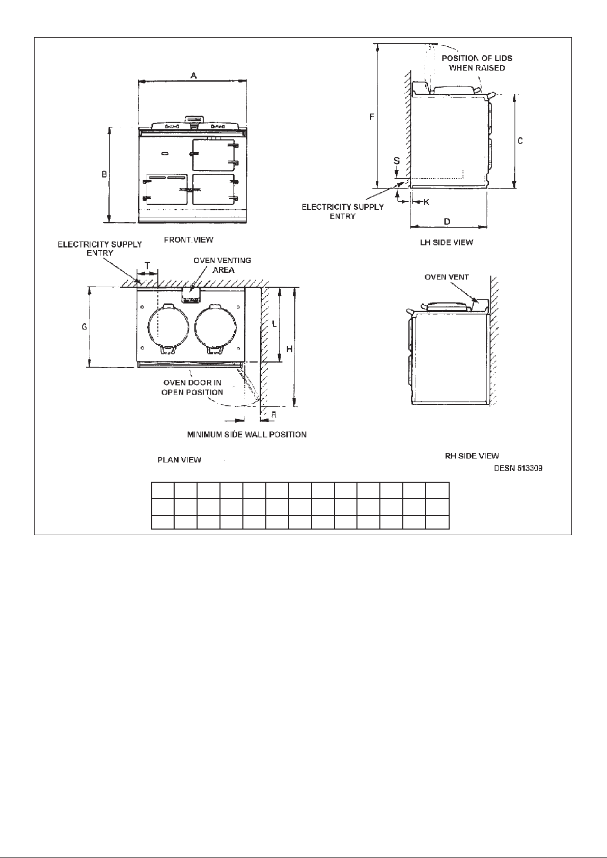
ABCDFGHKL
RST
116 55 114
mm
987 889 851 679
1330
756
1125 12
698
5
EC-LM MODEL
Fig. 1
ins
38 7/8
35
33 1/2 26 3/4 51 3/4 29 3/4 44 1/41/2 27 1/2 4 9/16 2 3/16 4 1/2
Page 6
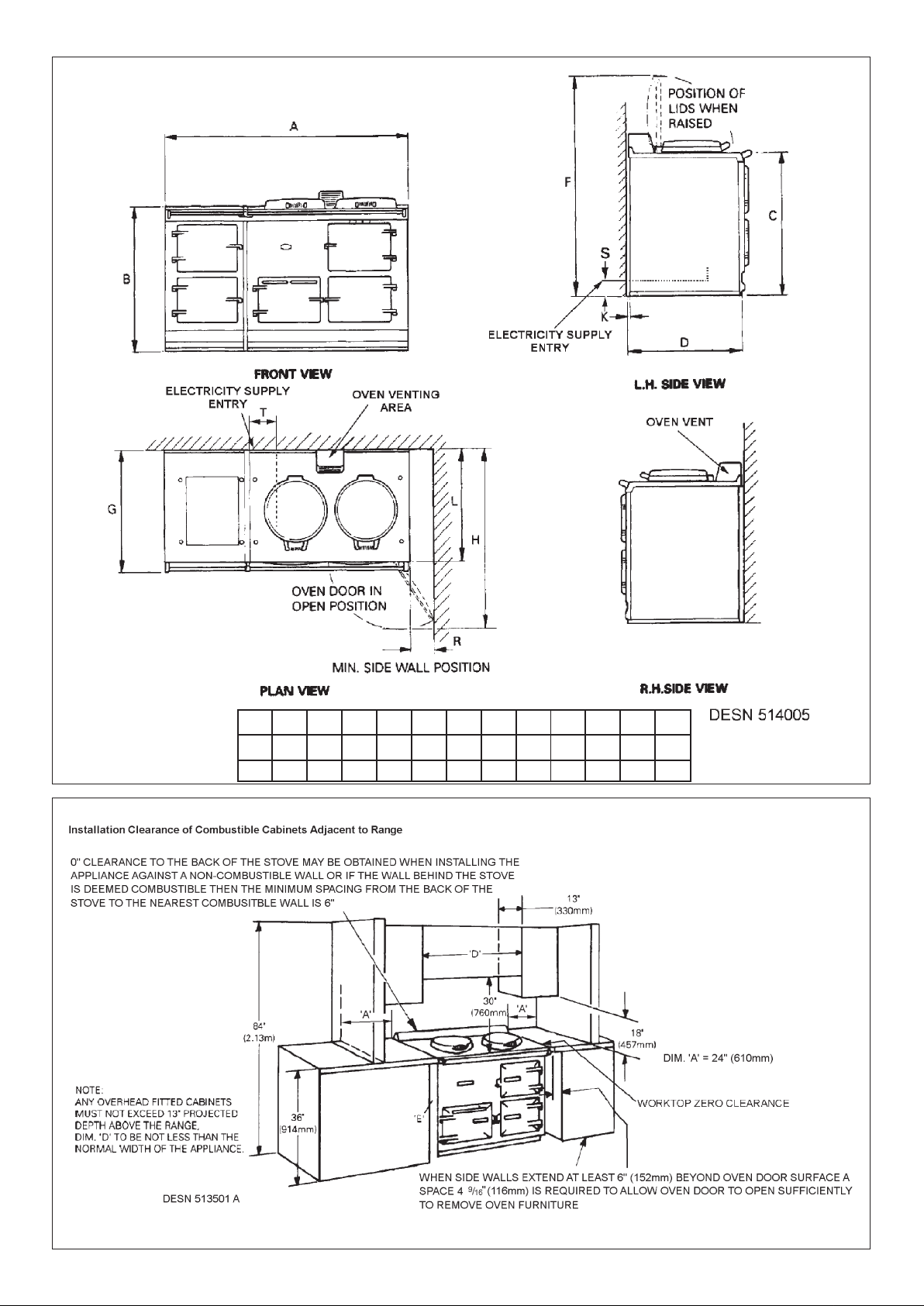
Fig. 1B
EE-LM MODEL
Fig. 1A
6
ABCDFGHKL
RST
116 55 114
mm
1487
889 851 679
1330
756
1125 12
698
ins
58 1/2
35
33 1/2 26 3/4 51 3/4 29 3/4 44 1/41/2 27 1/2 4 9/16 2 3/16 4 1/2
Page 7

ELECTRICAL CONNECTION
INSTRUCTIONS
ELECTRICAL TEST PROCEDURE
An electrical socket must be provided within 6 feet of the LH side of the appliance and easily accessible to the user to
disconnect. Do not position socket above the appliance.
Electric Shock Hazard
Electrical Grounding is required on this appliance.
Do Not connect to the electrical supply until the appliance is permanently grounded.
Disconnect the power to the junction box before making the electrical connection.
This appliance must be connected to a grounded, metallic, permanent supply or a grounding connector should
be connected to the grounding terminal or wire lead on the appliance.
Failure to follow these instructions could result in death or serious injury.
This range must be supplied with a 240V, 60 Hz power supply and connected to an individual, properly grounded branch
circuit protected by a circuit breaker of time delay fuse. At 240V, it is rated 2.5 kW, 13 Amps. Electric hook-up must be
done by licensed electrician. This unit must be installed according to local code, or in the absence of local codes, the
National Electrical Code for the country of installation.
Wire sizes (COPPER WIRE ONLY) and connections must conform with the rating of the range (30-amperes).
z The wiring diagram is located on the back of the L.H. door.
THIS APPLIANCE MUST HAVE THE FACILITY OF BEING COMPLETEL YISOLA TED FROM THE ELECTRICITY
SUPPLY.
THE APPLIANCE MUST BE COMPLETELY ISOLATED FROM THE ELECTRICITY SUPPLY BEFORE
SERVICING.
WARNING
Electrical Grounding Instructions
This appliance is equipped with a grounding pin for your protection against a shock hazard. The power cord should be
plugged directly into a receptacle. Do not use an extension cord.
Hand this Owners Manual to the user for retention and instruct in the safe operation of the appliance.
Also advise the user that, for continued efficient and safe operation of the appliance, servicing is carried out at intervals
recommended by the Aga distributor.
Final Electrical Test - Electric Voltage - Withstand Test
Procedure:
(Earth Appliance Test Simulation)
1. Select 1200 volts Flash Test on test equipment.
2. Plug in supply plug into the test equipment.
3. Depress the ‘Test Button’ for 1 second.
4. A ‘Pass’ light will illuminate.
5. If the appliance fails this test, re-check all circuits and correct the fault and retest the range.
6. Disconnect from the test equipment and connect range to its permanent supply.
7. A full load test will be performed using a clamp meter connected to the incoming supply.
NOTE: The test results 10.5 -11 amps normal operation.
8. Make note of results and disconnect all leads.
7
Page 8

Fig. 2B
Fig. 2A
8
DESN 513533
Page 9

Users
Guide
9
Page 10

SAFETY PRECAUTIONS
This booklet has been prepared in the interest of providing you with basic information on the safe and correct use of your
Aga Range.
Instructions are provided on the operation and maintenance after-care of the Aga range and we would recommend that
you read this Owners Manual before you begin cooking.
NOTE: READ ALL INSTRUCTIONS BEFORE USING THIS RANGE.
USER SERVICING
Do not repair or replace any part of the appliance unless specifically recommended in this manual. All other servicing
should be performed by a qualified technician.
VENTILATING HOODS (WHERE APPLICABLE)
z Clean ventilating hoods frequently - grease should not be allowed to accumulate on the hood or filter.
z When flaming foods under the hood, turn the fan on.
BASIC RANGE SAFETY PRECAUTIONS
z Materials such as gasoline, vapors and liquids which can catch fire and explode must not be stored in, above or near
a range.
z Make sure that nothing is allowed to prevent the flow of air to the electric control compartment.
z Ensure space storage cabinets are capable of supporting the heavy weight of cooking utensils that are used on this
range.
z The maximum depth of any cabinets installed above the top of the range must not exceed 13” (330mm).
CHILD SAFETY
Children are more sensitive to heat than adults, therefore they MUST be made aware of the following safety precautions:
1. Do not leave children alone or unsupervised near the range and discourage them from this area.
2. Children should not be allowed to climb on any part of the range.
3. Children MUST be taught that the range and its utensils can be hot.
4. Children should be taught that the range is not a toy. They MUST not play with the range electric controls behind the
outer burner door or any other range parts.
5. Let the heavy, hot utensils cool in a safe place and out of reach of small children.
CAUTION: AVOID STORING ITEMS OF INTEREST TO CHILDREN IN ANY CABINETS INSTALLED ABOVE THE
RANGE TO PREVENT THE RANGE BEING USED TO OBTAIN ACCESS AND POSSIBLE SERIOUS INJURY.
10
Electric Shock Hazard
Electrical Grounding is required on this appliance.
Do Not connect to the electrical supply until the appliance is permanently grounded.
Disconnect the power to the junction box before making the electrical connection.
This appliance must be connected to a grounded, metallic, permanent supply or a grounding connector should
be connected to the grounding terminal or wire lead on the appliance.
Failure to follow these instructions could result in death or serious injury.
Page 11

DO NOT TOUCH SURFACE UNITS OR AREAS NEAR UNITS - SURFACES MAY BE HOT. Areas near surfaces units
may become hot enough to cause burns, do not touch, or let clothing or other flammable materials contact surface units
or areas near units.
GREASE
WARNING: HOT GREASE IS FLAMMABLE.
Wipe off any grease deposits on the range top and front. Do not leave containers of cooking fat around the range. In the
event of a grease fire, do not remove the pan, cover the pan to extinguish the flame.
WARNING: DO NOT DOUSE FLAME WITH WATER
Use a dry chemical type fire extinguisher if available, or sprinkle heavily with baking soda.
RANGE COOKING SAFETY PRECAUTIONS AND HINTS
Never reach directly into a hot oven to add or remove cooking utensils. Instead pull the grid shelf out to its maximum
projection and load or remove utensils.
Use oven gloves to remove hot utensils.
NEVER WEAR LOOSE FITTING OR HANGING GARMENTS WHILE USING THE RANGE.
USE ONLY DRY POTHOLDERS - Moist or damp potholders on hot surfaces may result in burns from steam. Do not let
potholder touch hot heating elements. Do not use a towel or other bukly cloth.
Although the range itself provides gentle radiant heat and convected warm air currents, it MUST NOT be used to increase
space heating by leaving the insulating covers permanently raised or the oven doors left open. This instruction is based
on safety considerations where accidents occur, as does the use of ovens for storage space.
WARNING: DO NOT HEAT A CLOSED GLASS OR METAL CONTAINER IN THE OVEN.
Pressure build-up in the container may cause it to burst and result in injury.
Use care when opening oven door - Let hot air or steam escape before removing or replacing food.
Keep oven ducts unobstructed.
General Safety Precautions and Hints for cooking utensils
1. Ensure utensils have flat machined bases to obtain perfect contact with the hotplate.
2. Ensure the correct size utensil is chosen to prevent food boil-over.
3. Always turn utensil handles away from the front of the range and out of reach of small children.
WARNING: NEVER LEAVE A DEEP FAT FRYING OPERATION UNATTENDED.
The following accessories are provided with the range:
1 Large meat tin with grill rack
1 Half size meat tin with grill rack
1 Plain oven shelf
1 Toaster
2 Grid oven shelves
1 Wire brush
SAFETY PRECAUTIONS (CONTINUED)
11
RANGE ACCESSORIES
Page 12

12
BLACK SILVER
too hightoo low
correct amount of
stored heat
RED
BLACK LINE
The heat indicator is above the roasting oven door and has three sections: black, silver and red. When the indicator is on
or about the black line in the silver section, the range is at the correct working temperature. The purpose of the heat
indicator is to show whether the range contains the full amount of stored heat. Therefore the heat indicator should only be
referred to first thing in the morning or after a period of several hours during which no cooking has been done.
NOTE: IT DOES NOT INDICATE THE OVEN TEMPERATURE.
THE HEAT INDICATOR
To turn the range off, switch off the electricity supply at the breaker panel.
When the range is in use, the control knob should be in the HIGH section (i.e. 4/5) of the numbered band (See Fig. 3),
with the indicator on or about the black line in the silver section of the heat indicator (see above). It may be necessary to
adjust the control knob slightly to achieve this.
Once the correct setting has been confirmed, the control will operate automatically to maintain the range at the correct
temperature and need not be adjusted.
THERMOSTAT CONTROL
DESN 513468
Fig. 3
Page 13

SERVICING
OPERATING YOUR AGA
For continued efficient and safe operation of the appliance, it is important to service the appliance at intervals
recommended by your authorised Aga Specialist.
The following points are intended to help you during the period of change-over from your previous range to the Aga way
of life. You will also find that the Aga Book provides a very useful introduction to the range.
After your Aga has been assembled
When first used, your Aga will emit an odour for a short while. Do not worry, this is simply due to protective oil burning off
the hotplates. If the inside of the hotplate lids are wiped while the Aga is heating up it will avoid a film of this oil being
deposited on the inside of the lids.
Also, condensation may occur on the top plate and front plate while the Aga is heating up. This should be wiped away as
soon as possible.
Beginning to cook on your Aga.
Try to cook as much as possible in the ovens - without changing your menus. This not only conserves heat but also
reduces cooking smells and condensation in the kitchen.
The roasting oven can also be used for broiling (at the top) and shallow frying (on the bottom).
Keep the insulated covers down when the hotplates are not in use so that the heat stored in the cooker is conserved. For
optimum cooking performance, use Aga cookware. They will have thick bases which give the best contact with the
hotplates.
Most Aga pans can be stacked in the simmering oven. This is especially useful for steaming vegetables and simmering
sauces.
Store the plain shelf out of the Aga. Use it cold in the roasting oven to deflect the heat from the top of the oven, creating
a more moderate oven temperature. It can also be used as a baking sheet.
The Aga Cake Baker can be used in the Aga for cakes needing over 45 minutes cooking.
A guide to Aga cooking is given on the page 16. Ask your Aga specialist for an invitation to an Aga demonstration.
13
Page 14

FITTING OF OVEN SHELVES
DESN 512403
DESN 512404
Fig. 4
Fig. 5
If this is the first time you have used this type of oven shelf, go through the procedure of changing it with the aid of Figs.
4 to 7.
14
Page 15

REMOVAL OF OVEN SHELVES
DESN 512405
DESN 512406
Fig. 6
Fig. 7
15
Page 16

16
CLEANING AND CARING FOR YOUR AGA
REMEMBER: BE CAREFUL OF THE HOT APPLIANCE.
DO NOT USE A STEAM CLEANER TO CLEAN THIS COOKER.
DO NOT USE ABRASIVE PADS OR OVEN CLEANER.
Top Plate and Front plate
The easiest way to clean the Aga top plate and front plate is to mop up spills as they happen. Baked-on food is more
difficult to clean but can usually be removed with proprietary vitreous enamel cleaners or mild cream cleaners using a cloth,
or, if necessary, a nylon scouring pad. If milk or fruit juice or anything containing acid, is spilt on the Aga, wipe it up
immediately.
Also clean off any condensation streaks on the front-plate around the oven doors or the vitreous enamel may be
permanently discolored.
All that is usually needed to keep the vitreous enamelled surfaces of your Aga bright and clean is a daily rub over with a
damp soapy cloth followed immediately with a clean, dry cloth to avoid streaks.
Remember the top-plate and the stainless covers will scratch if pans or utensils are dragged across them.
Insulating Covers and Oven Doors
The linings of the insulating covers and oven doors may be cleaned with a cream cleanser or a soapy pad.
Open the covers and lift off the oven doors to allow them to cool a little before cleaning. Do not, however, immerse the
doors in water as they are packed with insulating material which will be damaged by excessive moisture.
Refer also to the Cleaning Section in the Aga Book.
Oven and Hotplates
The cast iron ovens help to keep themselves clean; they merely need to be brushed out occasionally with a long-handled
stiff brush. The simmering oven may be cleaned with a damp soapy cloth.
The wire brush is provided for cleaning the hotplates and any burnt-on spills in the cast iron ovens.
DO NOT USE ANY OVEN CLEANERS.
Roasting Tins
The roasting tins should be cleaned in hot soapy water, soaking if necessary. A nylon scouring pad can also be used.
DO NOT place in the dishwasher or use other caustic cleaners.
As the Aga Cooker is heated differently from an ordinary cooker, exact conversions are not possible. Look in the Aga Book for
a similar recipe. Below is a quick guide to oven usage.
GUIDE TO AGA COOKING
CASSEROLES
STOCK
MILK PUDDINGS
MERINGUES
RICH FRUIT CAKE
For Casseroles, Stock, Milk Puddings,
bring to heat elsewhere on the Aga then
transfer to Simmering Oven. (One
exception is Meringues). Rich Fruit Cakes
can be cooked for a long time here
For Casseroles, Stock, Milk Puddings,
bring to heat elsewhere on the Aga then
transfer to Simmering Oven. (One
exception is Meringues). Rich Fruit Cakes
can be cooked for a long time here.
LOW SIMMERING OVEN SIMMERING OVEN
CAKES
BISCUITS
FISH
SOUFFLÉS
SHORTBREAD
CHEESECAKES
Place grid shelf on floor of Roasting Oven.
Protect food with the cold plain shelf slid
on second or third runners. For cakes that
require over 45 mins use the Cake Baker.
Alternatively with fish, cheesecake, start
off in Roasting Oven, finish in Simmering
Oven.
Towards top - Whisked Sponges,
Some Biscuits, Small Cakes
Middle - Fish, Soufflés.
Grid shelf on oven floor - Victoria
Sandwiches, Shortbread and
Cheesecake
MODERATE ROASTING/SIMMERING OVEN BAKING OVEN
GRILLING
SCONES
PASTRIES
BREAD
YORKSHIRE PUDDING
ROASTS
SHALLOW FRYING
Top - Grilling;
2nd runner - Scones, Small Pastries;
3rd runner - Bread Rolls, Yorkshire
Pudding;
4th runner - Roasts, Poultry, Small Cakes
in cases in the large meat tin.
Grid shelf on oven floor - Loaves.
Oven floor - Shallow frying. Quiche.
Top - Grilling;
2nd runner - Scones, Small Pastries;
3rd runner - Bread Rolls, Yorkshire
Pudding;
4th Runner - Roasts, Poultry.
Grid shelf on oven floor - Loaves
Oven floor - Shallow frying, Quiche.
HIGH ROASTING OVEN ROASTING OVEN
OVEN TEMPERATURE 2=TWO OVEN AGA
=4=
FOUR OVEN AGA
Page 17

171819
Page 18

Page 19

Page 20

20
For further advice or information please
contact your local Aga Specialist
With Aga-Range’s policy of continuous product
improvement, the Company reserves the right to
change specifications and make modifications to
the appliance described at any time.
110 Woodcrest Road
Cherry Hill
NJ 08003
800.633.9200
www.aga-ranges.com
 Loading...