

AGA DC3G Installation Manual

1
AGA DUAL CONTROL
Model No’s: DC3G
02/16 EINS 516911
For use in USA/Canada
Installation
Guide
PLEASE READ THESE INSTRUCTIONS BEFORE COMMENCING SITE SURVEY
OR INSTALLING THIS APPLIANCE.
IMPORTANT : SAVE INSTRUCTIONS FOR FUTURE REFERENCE
REMEMBER: when replacing a part on this appliance, use only replacement parts
that you can be assured conform to the safety and performance specification that
we require. Do not use reconditioned or copy parts that have not been clearly
authorized by AGA.

2
SECTION PAGE
PRODUCT SAFETY 3
GENERAL NOTES 4
DELIVERY REQUIREMENTS 4
GENERAL INSTALLATION REQUIREMENTS 4
APPLIANCE DIMENSIONS - AGA DC3G 5
TECHNICAL DATA 6
INSTALLATION 6 - 9
CONNECTION TO THE POWER SUPPLY - AGA DC3G 10
MAINS CABLE ROUTING - AGA DC3G 11
FLUE SYSTEM 12 - 15
WIRING DIAGRAM - AGA DC3G 16
GAS SUPPLY - U.S. PIPE THREADS 17
AIR SUPPLY 17
AGA DC3G P/F HANDRAIL CONNECTION 18 - 19
COMMISSIONING 20 - 21
YEARLY SERVICE 21 - 22
REPLACEMENT PARTS 22
INSTRUCTIONS 22
BURNER CONTROLS 23
CONTENTS LIST (LOOSE ITEMS) 24
CONTENTS
3
PRODUCT SAFETY
MEANING/DESCRIPTION SIGNIFICATION/DESCRIPTIONSYMBOL
WARNING/CAUTION
An appropriate safety instruction
should be followed or caution to a
potential hazard exists.
AVERTISSEMENT
Une consigne de sécurité
appropriée doivent être suivies ou
garde d’un danger potentiel
exists.
DANGEROUS VOLTAGE
To indicate hazards arising from
dangerous voltages.
TENSION DANGEREUSE
Pour indiquer les dangers
résultant des tensions
dangereuses.
PROTECTIVE EARTH (GROUND)
To identify any terminal which is
intended for connection to an
external conductor for protection
against electric shock in case of a
fault, or the terminal of a
protective earth (ground)
electrode.
TERRE DE PROTECTION
Pour marquer bornes destin
ées à
être raccordées à un conducteur
de protection extérieur contre les
chocs éclectiques en cas de
défaut d’isolement, ou pour
marquer la borne de la terre de
protection.
HEAVY
This product is heavy and
reference should be made to the
safety instructions for provisions
of lifting and moving.
LOURD
Ce produit est lourd et doit
être
fait référence auc consignes de
sécurité relatives aux dispositions
de soulever et déplacer.
DISCONNECT MAINS SUPPLY
Disconnect incoming supply
before inspection or maintenance.
APPAREIL À LASER DE
CLASSE 2
Alimentation d’entr
ée Débrancher
avant inspection ou d’entretien.
REFER TO MANUAL
Refer to relevant instructions
detailed within the product
manual.
ATTENTION, SURFACE TRÉS
CHAUDE
Reportez-vous aux instructions
applicables, indiquées dans le
manuel du produit.
4
GENERAL NOTES
NOTE: THESE INSTALLATION INSTRUCTIONS SHOULD BE LEFT WITH THE RANGE AND THE USER TO
RETAIN FOR FUTURE REFERENCE.
DELIVERY REQUIREMENTS
The AGA DC3 arrives on 1 pallet.
Vent Pipe Installation kit (AG1M212542) arrives in a separate carton.
There must be access to the kitchen to manipulate a foot print of 39 9/16” (1005mm) x 29 1/8” (740mm). A
wooden template (skate with castor wheels) of dimensions 39 9/16” (1005mm) x 29 1/8” (740mm) could be
used to check if the AGA Dual Control fully built appliance is able to fit through the property grounds and
doors into its installation position in the kitchen. It must also be considered that the height of the appliance is
37 3/4” (960mm) off pallet and 43 1/4 ” (1100mm) on the pallet, so high level obstacles/restrictions must not be
overlooked.
GENERAL INSTALLATION REQUIREMENTS
The installation of the range must be in accordance with the relevant requirements of the local Wiring and
Building Regulations. It should be in accordance also with any relevant requirements of the local or state codes.
In your own interest and that of safety to comply with the law, all appliances should be installed by an authorized
AGA distributor in accordance with the relevant regulations.
CAUTION:
THIS UNIT IS HEAVY, PROPER EQUIPMENT AND ADEQUATE
MANPOWER MUST BE USED IN MOVING THE RANGE TO
AVOID DAMAGE TO THE UNIT OR THE FLOOR
5
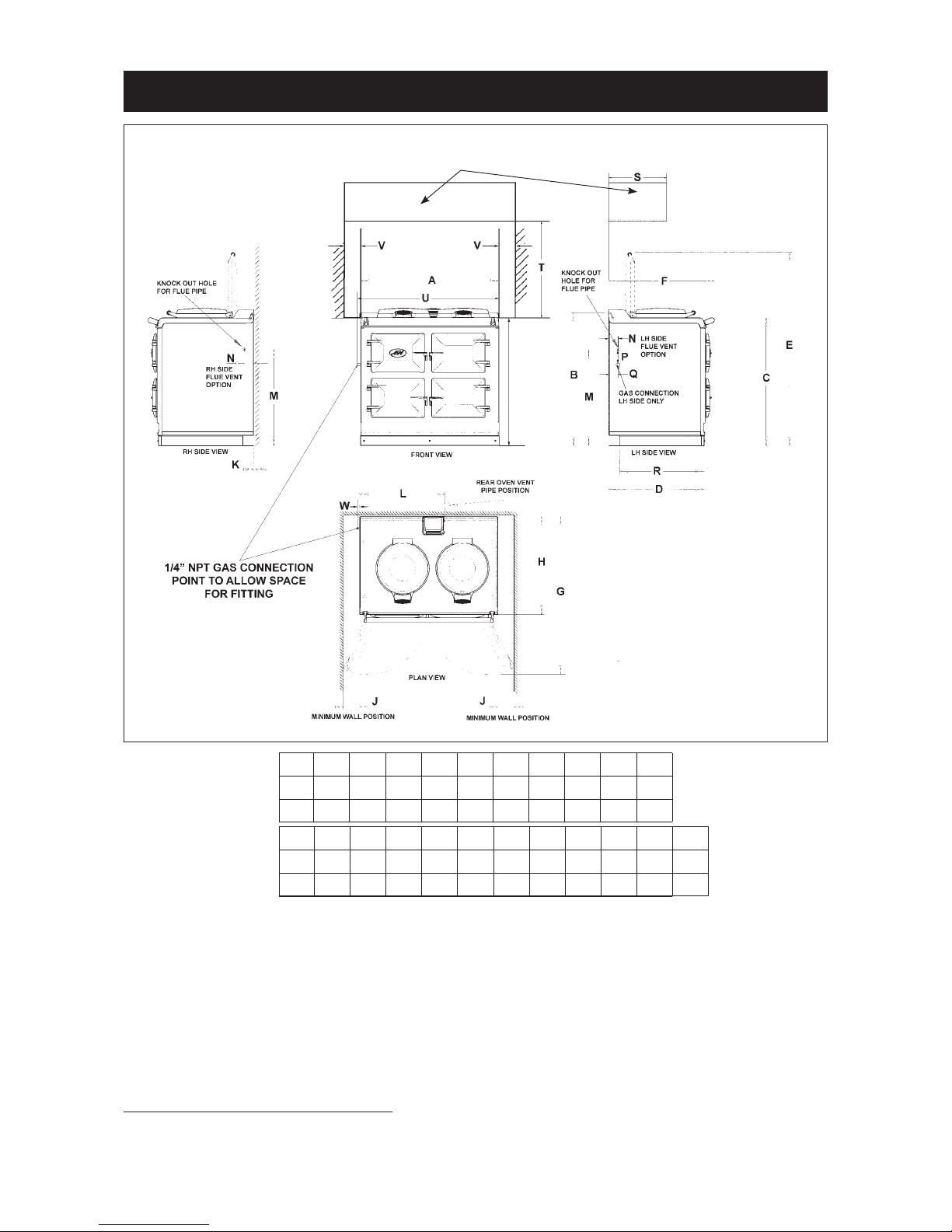
APPLIANCE DIMENSIONS - AGA DC3G
Fig. 1 DESN 516847 A
Range Dimensions
When surveying for a range installation the actual clearance required for the ‘body’ of the appliance should
be increased by 3/8” beyond the figures quoted above. This allows safe margin to take into account the
natural dimensional variations found in major castings. In particular the width across the appliance recess
could be critical.
APPLIANCE WEIGHT (Excludes Packaging)
Model: AGA Dual Control (DC3G) - 996lb (452kg)
GAS CONNECTION - AGA DC3G ONLY
1/4” NPT MALE AT LEFT REAR OF APPLIANCE
NOTE: GAS CONNECTION POINT PROTRUDES
A B C D E F G H J K
mm 987 951 913 680 1388 760 1145 698 116 10
inch
38
7/8 37
1/2 36 26 3/4 54
5/8 29 7/8 45
1/8 27
1/2 4
9/163/8
L M N P Q R S T U V W
mm 565 689 43 118 55 634 330 760 996 75 9
inch
22
1/4 27
1/8 1
3/4 4
5/8 2
1/8 25 13 30 39
3/16 33/8
OVERHEAD
CUPBOARDS
6
Side Clearances
A
1
/8” (3mm) gap is required each side between the range top plate and adjoining work surfaces that may be
fitted, this is to allow for the safe removal of the top plate should this be required at a later date.
Where ranges are to be fitted against a side wall a 4 9/16” (116mm) clearance is required on the right and left
hand side for oven door access.
If the AGA is to be installed in a brick recess, then the minimum clearance should be increased by at least
3
/8” (10mm), to allow for the walls not being square.
In addition a minimum clearance of 39 3/8” (1000mm) must be available at the front of the range to enable the
range to be serviced.
NATURAL GAS
MAXIMUM HEAT INPUT 6,800 Btu/hr
Thermostat Bypass 70
Main Burner Injector 112
Gas Supervision Injector 4212
Minimum Inlet Pressure 5” w.g.
Burner Pressure 4” w.g.
Models AGA DC3G and DC5G
TECHNICAL DATA
INSTALLATION
Range Base or Hearth
It is essential that the base or hearth on which the range stands should be level and be capable of supporting
the total weight of the range. The base of the built-in AGA plinth must be level and sit above the finished
height for service access.
Plinth
The front plinth cover is removable and must not be obstructed by flooring or tiles. If necessary the range
must be raised by the thickness of the tiles to ensure the plinth can be removed.
Rear Wall
Since this appliance runs continuously, please take note of these IMPORTANT instructions:
Combustible Walls
Houses constructed of combustible materials (such as all-timber or stud wall partitions and batoned
plasterboarded walls) require special wall heat protection features.
Non-combustible material behind a range must be of at least 1” (25mm) thick insulation board (Monolux or
equivalent), up to hotplate level.
SPECIAL NOTE: Ensure electric cabling or plastic services do not pass within or on the outside of the wall,
behind or directly above the range.
This type of material can age prematurely when exposed to continuous higher ambient temperature.
Alternatively the range can be spaced 1 1/2” (38mm) away from the wall to create an air gap.
The air gap must be left open and NOT blocked off across the top edge.

7
Tiling
When the range is to stand in a recess or against a wall which is to be tiled, under no circumstances should
the tiles overlap the range top plate, access to remove the hotplate must be allowed for servicing at a later
date.
A gap of at least
3
/8” (10mm) must be observed from the rear of the top plate and the wall behind the range.
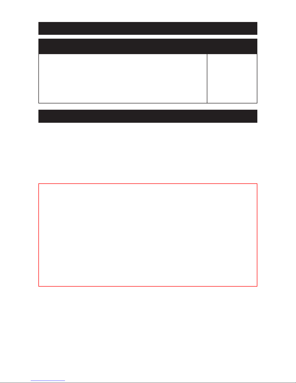
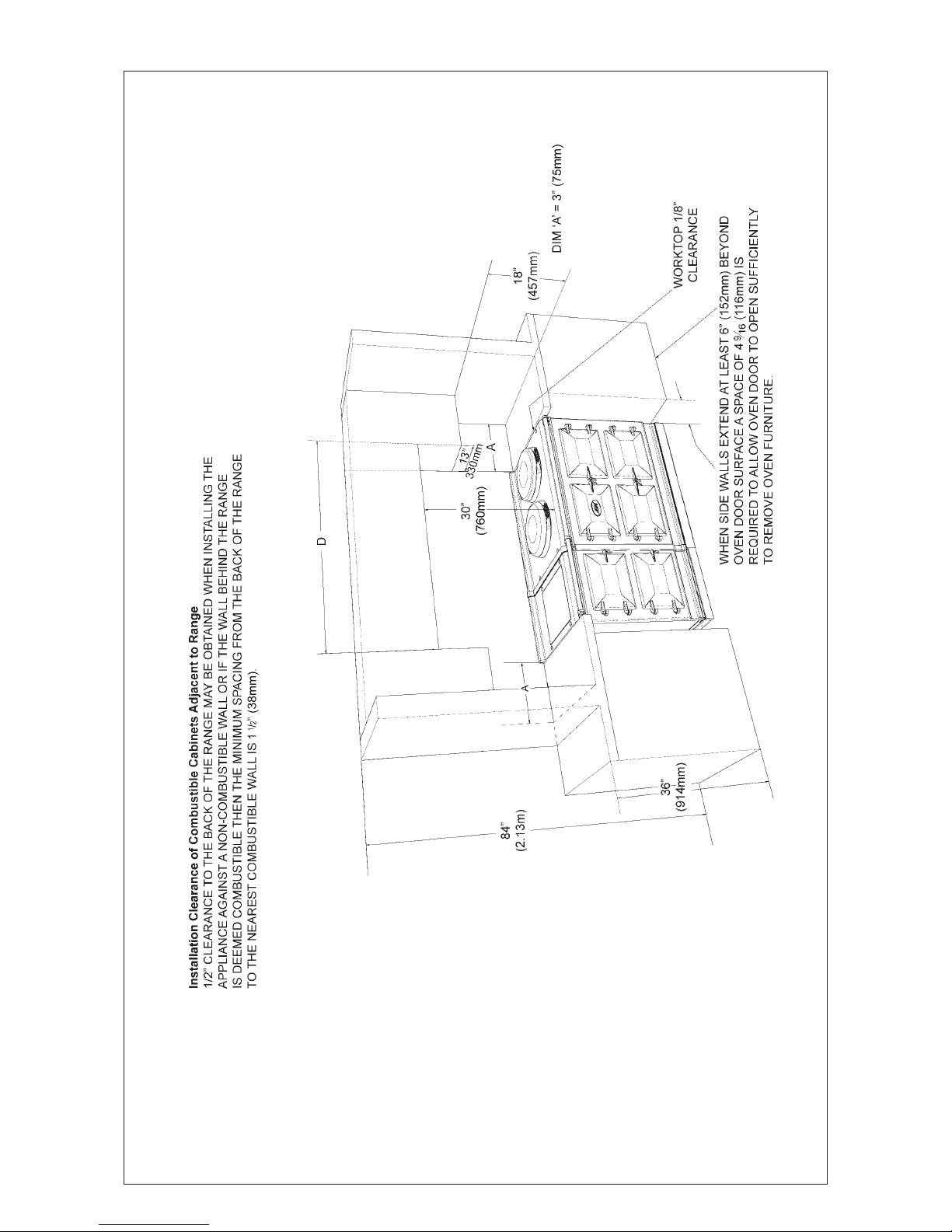
Overhead Cabinets
To eliminate the risk of burns or fires by reaching over hot surface units, cabinet storage space located
above the surface units should be avoided.
8
NOTE: ANY OVERHEAD FITTED
CABINETS MUST NOT EXCEED 13”
PROJECTED DEPTH ABOVE THE
RANGE.
DIM ‘D’ TO BE NOT LESS THAN THE
NORMAL WIDTH OF THE RANGE.
Fig. 2 DESN 516668
9
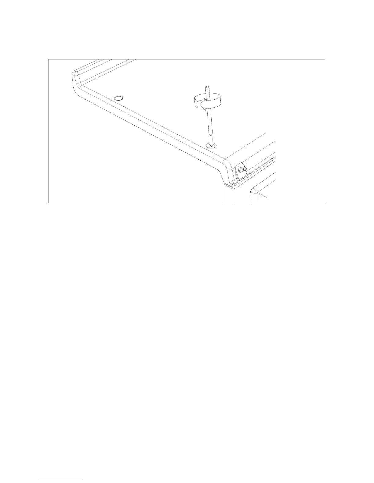
Top Plate Adjustment - AGA DC3 (See Fig. 4)
In general, adjustment of the top plate is to be avoided. However minimum use of the top plate adjusters can
be used to improve the alignment of the top plate.
Fig. 3
DESN 516751
 Loading...