

Page 1
Installation
Guide
05/15 EINS 516899
PLEASE READ THESE INSTRUCTIONS BEFORE COMMENCING SITE SURVEY
OR INSTALLING THIS APPLIANCE.
IMPORTANT : SAVE INSTRUCTIONS FOR FUTURE REFERENCE
IMPORTANT : CONSERVER CES INSTRUCTIONS POUR REFERENCE FUTURE
For use in USA/Canada
AGA CITY24
Page 2

SECTION PAGE
PRODUCT SAFETY 3
GENERAL NOTES 4
HEALTH AND SAFETY 4
GENERAL INSTALLATION REQUIREMENTS 4
REMOVAL FROM PALLET AND RANGE INSTALLATION 5-6
RANGE DIMENSIONS 7
CLEARANCES 8 - 9
CONNECTION TO THE POWER SUPPLY 10
POWER CORD ROUTING 11
CONTROL KNOB AND HANDRAIL CONNECTION 12
WIRING DIAGRAM 13
AGA CITY24 CHECKLIST 14
2
CONTENTS
Page 3
PRODUCT SAFETY
MEANING/DESCRIPTION SIGNIFICATION/DESCRIPTIONSYMBOL
WARNING/CAUTION
An appropriate safety instruction
should be followed or caution to a
potential hazard exists.
AVERTISSEMENT
Une consigne de sécurité
appropriée doivent être suivies ou
garde d’un danger potentiel
exists.
DANGEROUS VOLTAGE
To indicate hazards arising from
dangerous voltages.
TENSION DANGEREUSE
Pour indiquer les dangers
résultant des tensions
dangereuses.
PROTECTIVE EARTH (GROUND)
To identify any terminal which is
intended for connection to an
external conductor for protection
against electric shock in case of a
fault, or the terminal of protective
earth (ground) electrode.
TERRE DE PROTECTION
Pour marquer bornes destin
ées à
être raccordées à un conducteur
de protection extérieur contre les
chocs éclectiques en cas de
défaut d’isolement, ou pour
marquer la borne de la terre de
protection.
HEAVY
This product is heavy and
reference should be made to the
safety instructions for provisions
of lifting and moving.
LOURD
Ce produit est lourd et doit
être
fait référence auc consignes de
sécurité relatives aux dispositions
de soulever et déplacer.
DISCONNECT MAINS SUPPLY
Disconnect incoming supply
before inspection or maintenance.
APPAREIL À LASER DE
CLASSE 2
Alimentation d’entr
ée Débrancher
avant inspection ou d’entretien.
REFER TO MANUAL
Refer to relevant instructions
detailed within the product
manual.
ATTENTION, SURFACE TRÉS
CHAUDE
Reportez-vous aux instructions
applicables, indiquées dans le
manuel du produit.
3
Page 4
HEALTH AND SAFETY
Consumer Protection
As responsible manufacturers we take care to make sure that our products are designed and constructed to meet the
required safety standards when properly installed and used.
PLEASE READ THE ACCOMPANYING WARRANTY
Any alteration that is not approved by AGA could invalidate the approval of the appliance, operation of the warranty and
could also affect your statutory rights.
4
GENERAL NOTES
NOTE: THESE INSTALLATION INSTRUCTIONS SHOULD BE LEFT WITH THE RANGE AND THE USER TO RETAIN
FOR FUTURE REFERENCE.
GENERAL INSTALLATION REQUIREMENTS
The installation of the range must be in accordance with the relevant requirements of the local Wiring and Building
Regulations. It should be in accordance also with any relevant requirements of the Local Authority.
In your own interest and that of safety to comply with the law, all appliances should be installed by an authorized AGA
distributor in accordance with the relevant regulations.
CAUTION:
THIS UNIT IS HEAVY, PROPER EQUIPMENT AND ADEQUATE
MANPOWER MUST BE USED IN MOVING THE RANGE TO
AVOID DAMAGE TO THE UNIT OR THE FLOOR
Page 5
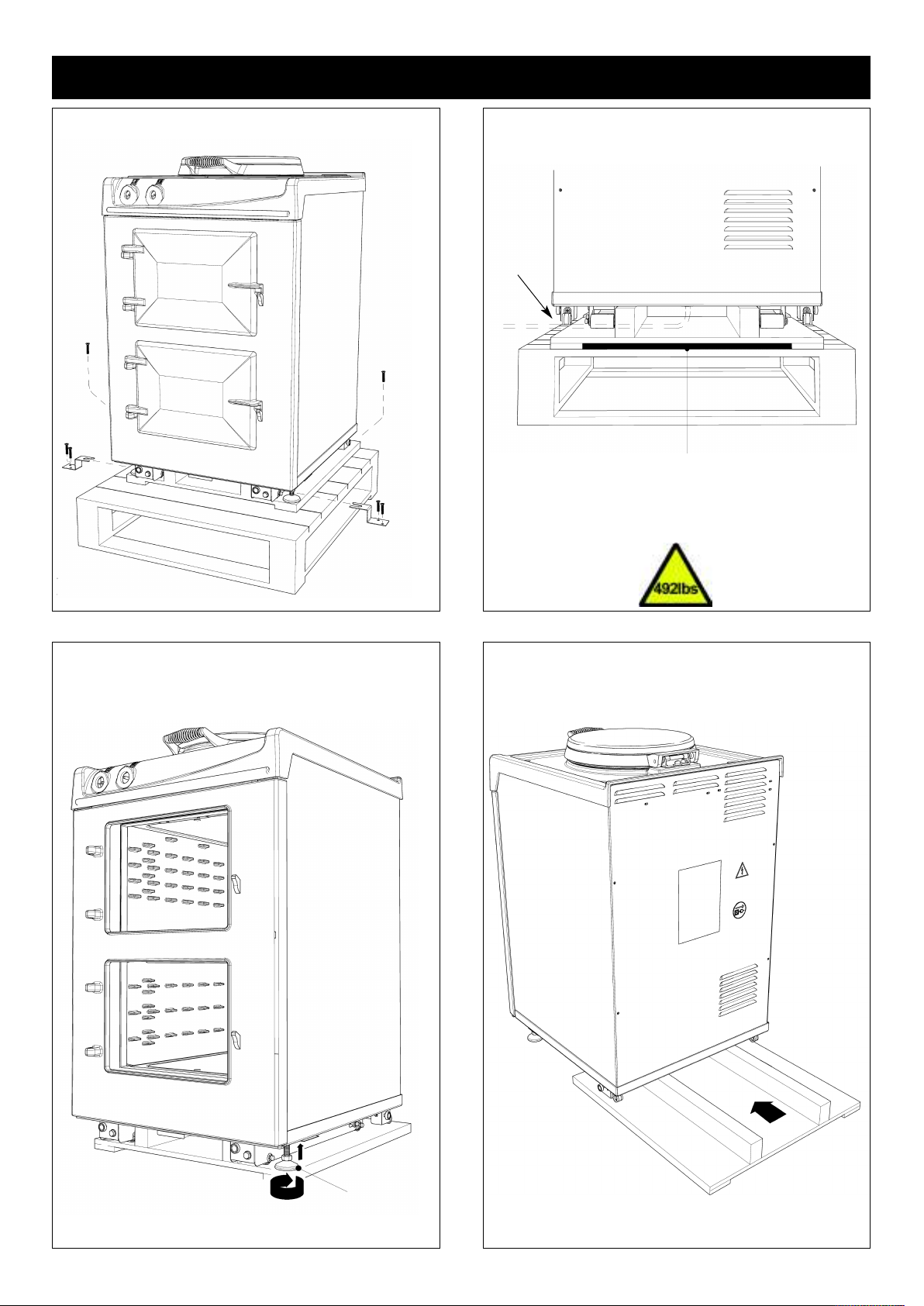
REMOVAL FROM PALLET AND RANGE INSTALLATION
Fig. 1 DESN 516905
Removing of transit brackets - Unscrew 4 screws and
remove brackets, from front and two screws from rear.
Fig. 2 DESN 516891
NOTE: Care must be taken not to trap power cord.
Range to be removed from rear of pallet only.
Recess provided for suitable appliance dolly.
Range to be secured to appliance dolly with
suitable straps (shaded area)
Fig. 3 DESN 516906
Once range is in position in kitchen, remove appliance
dolly and straps. The front stability feet can be raised
with a 12mm open end wrench to allow appliance to be
slid from transit pallet.
STABILITY FOOT
MAINS
CABLE
Fig. 4 DESN 516893
Slide range off transit pallet. Take care not to trap mains
cable.
5
Page 6

REMOVAL FROM PALLET AND RANGE INSTALLATION
Fig. 5 DESN 516907
Range can now be pushed back on its wheels into
desired position.
NOTE: Care must be taken not to trap mains cable.
Fig. 6 DESN 516895
Levelling of range - Use 13mm socket to adjust wheel
mechanism for FINE adjustment on both sides at rear
of the appliance.
Using a 12mm open end wrench, feet can be adjusted
at front to make FINE adjustments to the front of the
appliance and to provide a brake for the wheels.
Turning the bolt clockwise will lower the wheel thus
increasing height of the range.
Anti-clockwise lifts the wheels and lowers the range.
Fig. 7 DESN 516897
Fitting magnetic plinth
FRONT PLINTH
COVER FITS
OVER SIDE SKIRTS
MAKE SURE SIDE
PLINTH SKIRTS ARE
LOCATED IN FRONT
GUIDE BRACKET
Fig. 8 DESN 516888
Resting Plate Adjustment - Resting plates have
adjuster screw feet for setting of height and to improve
stability.
6
DESN 516917
Page 7

RANGE DIMENSIONS - AGA CITY24
Fig. 9 DESN 516904
APPLIANCE WEIGHT (Excludes Packaging)
Model: AGA CITY24 - 492lbs (223kg)
7
Page 8

CLEARANCES
8
The range top plate casting width tapers outwards at its bottom edge. Consequently adjacent cupboard units should have
a maximum depth of 23 3/8” (595mm) (including doors). If they are deeper, use the range rear spacer brackets to bring the
range forward. This will create a 1” (25mm) distance from the range front plate to cupboard doors.
The thickness of adjacent worktops should not exceed 1 3/4” (5mm).
Range Base or Hearth
It is essential that the base or hearth on which the range stands should be level and be capable of supporting the total
weight of the appliance.
The front plinth cover is removable and must not be obstructed by flooring or tiles. If necessary the range must be raised
by the thickness of the tiles to ensure the plinth can be removed, and the range can be rolled out for service.
Tiling
When the range is to stand in a recess or against a wall which is to be tiled, in no circumstances should the tiles overlap
the range top plate, access to remove the top plate must be allowed for servicing at a later date.
Fig. 9A DESN 516983
Side Clearances
If you are installing a AGA City24 in a new kitchen or have the opportunity to set the width between kitchen units, it is
advisable to include an additional small gap each side of
1
/8” (3mm) to assist with installation and prevent damage when
moving the product.
A 15/64” (6mm) additional width clearance should also be provided if the range is to go into a brick recess, to allow for the
wall being out of square.
Where it is installed against a side wall protruding in the front of the range a 4 9/16” (116mm) clearance is required on the
left hand side for oven door access.
Fitting into a 24” (60cm) gap
If you are restricted to a 24” (60cm) width space, the AGA City24 will fit, subject to the following guide. Please refer to Fig.
9A.
Page 9

Combustible Rear Walls
Since this range can be used continuously, please take note of the IMPORTANT INSTRUCTIONS.
Where the rear wall is constructed of combustible materials (such as all-timber or stud wall partitions and batoned
plasterboard) these will require special wall heat protection measures.
Non-combustible insulation board as a protective cladding can be used behind the range of at least
5
/8” (15mm) thick, such
as Monolux or equivalent. This should be taken up to hotplate level. See Fig. 9B.
Alternatively the range can be spaced away from the wall to create an air gap, using the 1” (25mm) spacer brackets supplied
with the range. See Fig. 9C.
The air gap must be left open and NOT blocked off across the top edge. See Fig. 9D.
Fig. 9B DESN 516984 DESN 516958
Fig. 9C
DESN 516985Fig. 9D
SPECIAL NOTE: Ensure that unprotected electric cabling
or plastic services do not pass within or on the outside of
the wall behind or directly above the range. This type of
material can age prematurely when exposed to continuous
higher temperature.
Other Clearances
A minimum clearance of 24” (60mm) is required above the
raised insulating cover handle.
A minimum clearance of 39 5/8” (1000mm) must be
available at the front of the range to enable it to be
serviced.
9
Page 10

10
CONNECTION TO THE POWER SUPPLY
Electric Shock Hazard
Rating Plate is located behind removable plinth, see Fig. 4.
Electrical Grounding is required on this appliance.
DO NOT connect to the electrical supply until the appliance is permanently grounded.
This appliance must be connected to a grounded metallic permanent supply or a grounding
connector should be connected to the grounding terminal or wire lead on the appliance.
Failure to follow these instructions could result in death or serious injury.
This range must be supplied with a 240V, 60Hz power supply and connected to an individual, properly grounded branch
circuit protected by a circuit breaker. At 240V, it has a maximum load of 30 amps. Electric hook-up must be done by a
licensed electrician. This unit must be installed according to regional codes, or in the absence of codes, the National
Electrical Code.
l Product installation requires a separate (not shared) 240V/40 amp circuit protected by an appropriate branch circuit
supply.
l The power cord on your range is fitted with a standard four (4) conductor type 14-50P plug (matching receptacle
14-50R).
The method of connection to the mains electricity supply must facilitate complete electrical isolation of the appliance.
The mains connection and isolation should not be positioned above the range and must be positioned within the area
defined in Fig. 11, Page 11.
A fully recessed range connection box may be located immediately behind the range (in the hatched area only as shown in
Fig. 11), however the 1” (25mm) spacers (provided with the range) must be fitted.
THIS RANGE MUST BE COMPLETELY ISOLATED FROM THE ELECTRICITY SUPPLY BEFORE SERVICING. THE
RANGE IS DESIGNED FOR THE VOLTAGE STATED ON THE RATING PLATE, WHICH IS SITUATED BEHIND THE
PLINTH COVER.
Page 11

MAINS CABLE ROUTING
Fig. 10 DESN 516918
11
SECURE MAINS CABLE USING ‘P’ CLIPS FOR LEFT HAND OR RIGHT HAND
CABLE MANAGEMENT
Fig. 10A DESN 516919
POWER CORD
50A/250V 12500W RATED FITTED WITH NEMA 14-50P RIGHT ANGLED PLUG
(MATCHING RECEPTACLE 14-50R)
UL OR CSA APPROVED
Fig. 11 DESN 516874 A
THE MAINS SUPPLY MUST BE WITHIN THE ZONES SHOWN
IF A RECESSED RANGE CONNECTION IS TO BE USED BEHIND THE RANGE
WITHIN THE HATCHED AREA. THE 1” (25mm) SPACERS PROVIDED MUST
BE FITTED
WORKTOP
3ft 11” (1.2 metres)
3ft 11” (1.2 metres)
RATING PLATE LOCATED BEHIND PLINTH
Page 12

CONTROL KNOB AND HANDRAIL CONNECTION
Fig. 12 DESN 516875
Control Knob Location
Ensure control knobs are located onto spindles correctly, as shown in Fig 12.
Handrail Location - AGA City24 (Traditional)
Locate handrail onto spindle, lock into position with grub screws (located on the inside of the bracket).
12
OVEN CONTROL
KNOB
HOTPLATE CONTROL
KNOB
Page 13

WIRING DIAGRAM
13
Fig. 13
Page 14

Tick Box
l Check hotplate lid and setting
l Check oven door seals, adjust door alignment if necessary.
Slow cook oven rope seals MUST have a gap between the door hinges. The roasting
oven is fitted with a continuous seal.
Ensure all plastic film is removed from the inside of the oven doors.
l Turn on roasting and slow cook oven, set hotplate to simmer. Raise hotplate lid to avoid staining.
l After 30 minutes, check hotplate temperatures (approx).
1. Simmerspot (200 - 250°C)
then hotplate to boiling, after 15 minutes check temperature
2. Hotspot (330 - 380°C)
l Guide customer through the Users Instructions of the range, offering best practices on oven
maintenance, energy usage, enamel cleaning (boiled vegetable water staining on enamel etc.)
Engineer’s Signature ........................................................ Date ...........................
AGA CITY24 CHECKLIST
SERIAL No.
141516
Page 15

Page 16

www.agamarvel.com
Supplied by
AGA Marvel
1260 E. Van Deinse St.
Greenville, MI 48838
Business (616) 754-5601
Fax (616) 754-9690
Toll Free Telephone 800-223-3900
With AGA Marvel’s policy of continuous product im-
provement, the Company reserves the right to
change specifications and make modifications to
the appliance described and illustrated at any time.
For further advice or information contact
your local AGA Specialist
 Loading...