

Page 1

Installation
Instructions
Built-In
Dishwashers
AELTTDW
ALTTDW
AMCTTDW
AMPROTTDW
HCTTDW
Page 2

TABLE OF CONTENTS
Important Safety Instructions ...................................................................3
Tools Which May Be Needed ..................................................................4
Materials Which May Be Needed ............................................................5
Materials Supplied ...................................................................................6
Parts Supplied.....................................................................................6
Dishwasher Specications.......................................................................7
Enclosure Preparation .............................................................................8
Installing the Side Trim Strips ..................................................................9
Preparing the Water Connection ...........................................................10
Drain Preparation ..............................................................................10
Steam Protection Foil ............................................................................ 11
Installation .............................................................................................12
Drain Hose Connection, Water Supply & Electrical Connections .....12
Preparation of Water Supply .............................................................12
Electrical Connection .............................................................................14
Readjusting Foot Levels ........................................................................15
Adjusting Moveable Kickplate................................................................15
Installer Checklist ..................................................................................16
Final Instructions ...................................................................................16
Service & Registration ...........................................................................17
2
Page 3
IMPORTANT - PLEASE READ AND FOLLOW
WARNING
DANGER
CAUTION
WARNING
DANGER
WARNING
DANGER
CAUTION
WARNING
DANGER
CAUTION
WARNING
DANGER
CAUTION
• Please read this installation manual and particularly the safety instructions completely and carefully. They
will save you time and effort and help to ensure optimum dishwasher performance.
• Be sure to observe all listed warnings and cautions. Look particularly for the icons with exclamation
marks inside. The information icon also will provide important references.
WARNING
Indicates a potentially hazardous situation which,
if not avoided, could result in death or serious
injury.
NOTICE
Indicates a potentially hazardous situation which,
if not avoided, may result in damage to the
dishwasher,the tableware, the equipment, or the
environment.
CAUTION
Indicates a potentially hazardous situation which, if
not avoided,may result in injury. It may also be used
to alert against unsafe practices.
In addition to these instructions, the dishwasher
shall be installed:
• In accordance with all local codes or, in absence
of a local code,
• In the United States, with the national Electric
Code,
• In Canada, with the Canadian Electric Code
C22.1-latest edition/Provincial and Municipal
codes and/or local codes.
NOTICE
Installation should be performed by an insured
licensed plumber, contractor, or trained
installer. Installation performed by persons
other than this could result in improper
installation and property damage.
NOTICE
Do not discard any bags or items that come
with the original package until after the entire
installation has been completed.
Site Preparation
When installing the dishwasher, follow basic precautions, including the following:
• The dishwasher should only be converted from cord-connected to permanently connected by an
authorized service representative.
• Installation and repair should be performed by a qualied installer. Work by unqualied persons could be
dangerous and may void the warranty.
It is recommended that a thorough site inspection be conducted PRIOR to
unpacking and moving this appliance.
NOTICE
• The dishwasher drain hose must be installed with a drain loop at least 28" (710mm) off the cabinet oor;
otherwise the dishwasher may not drain properly.
• This dishwasher is intended for residential use only and should not be used in commercial
establishments.
• New Installation: If the dishwasher is a new installation, most of the work must be done before the
dishwasher is moved into place.
• Replacement: If the dishwasher is replacing another dishwasher, check the existing dishwasher
connections for compatibility with the new dishwasher, and replace parts as necessary.
• Inspect the Dishwasher: After unpacking the dishwasher and prior to installation, thoroughly inspect the
dishwasher for possible freight or cosmetic damage. Report any damage immediately.
To contact us, you may either call our toll-free number at 1-1-800-223-3900 or contact us via the website at
www.agamarvel.com
3
Page 4
IMPORTANT - PLEASE READ AND FOLLOW
• DO NOT operate the appliance if damaged, malfunctioning, partially disassembled, or if it has missing or
broken parts.
• Also follow the safety instructions of the use and care guide.
• To reduce the risk of electric shock, re, or injury to persons, the installer must ensure that the dishwasher
is completely enclosed at the time of installation.
• Only connect the dishwasher to the power supply when all installation and plumbing work is complete.
• If the dishwasher is installed in a location that experiences freezing temperatures (e.g. in a vacation home,
cabin, etc.), you must drain all the water from the dishwasher's interior. Water system ruptures that occur
as a result of freezing are not covered by warranty.
• Dishwasher must be secured to adjacent cabinetry using the brackets provided. Failure to do this may
cause damage to property or bodily injury.
• Connect to a properly rated, protected, and sized power supply circuit to avoid electrical overload.
The dishwasher is designed for an electrical supply of 120V (volts), 60Hz (hertz), AC, connected to a
dishwasher-dedicated, properly grounded electrical circuit with a fuse or breakers rated for 15 amperes.
Electrical supply conductors shall be a minimum of #16 AWG copper wire rated at 167°F (75°C) or higher.
These requirements must be met to prevent injury and machine damage. Consult a qualied electrician if
in doubt.
• DO NOT use any extension cord or portable outlet device to connect the dishwasher to a power supply.
• Ensure that any plastic wrappings, bags, small pieces, etc., are disposed of safely and kept out of the
reach of children. Danger of suffocation!
• Remove the dishwasher door when removing an old dishwasher from service or discarding it. Ensure that
the appliance presents no danger to children while being stored for disposal.
• Old appliances may contain materials that can be recycled. Please contact your local recycling authority
about the possibility of recycling these materials.
General Information
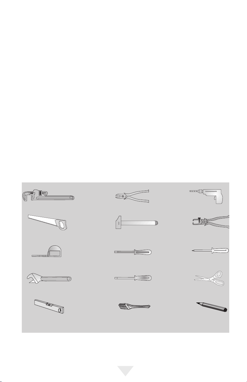
Tools Which May be Needed
Pipe Wrench Wire Cutter Drill
Hole Saw Hammer Wire Stripper
Tape Measure
Adjustable Wrench Slot Screwdriver Scissors
Level Brush Pencil
Torx Screwdriver (T20) Phillips Screwdriver
4
Page 5
GENERAL INFORMATION
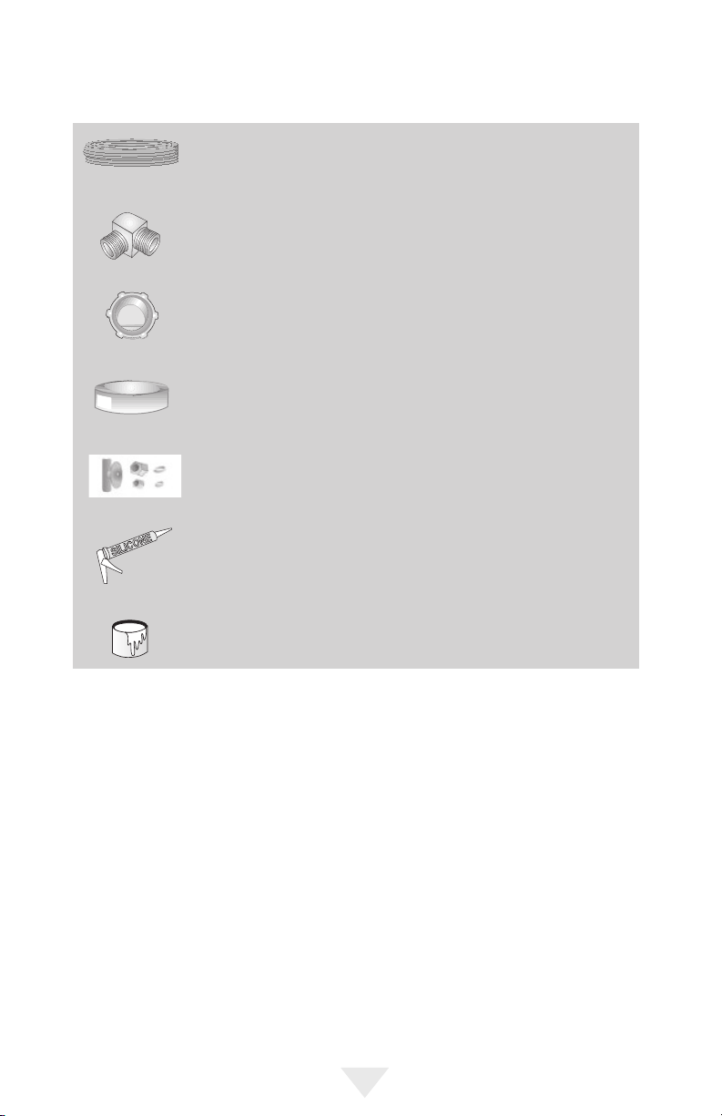
Materials Which May Be Needed
Hot Water Supply Line – Minimum 3/8" O.D. copper tubing or metal
braided dishwasher supply line.
90° elbow with 3/8" N.P.T. male threads on one leg, and sized to t
your water supply line (copper tubing/compression tting, or braided
hose) on the other leg.
UL listed conduit connector or strain relief.
Teon tape or other pipe thread compound to seal plumbing
connections.
Shut-off valve and ttings appropriate for hot water supply line
(copper tubing/compression tting, or braided hose).
Silicone
Glue
5
Page 6
GENERAL INFORMATION
Parts Supplied
Parts for your dishwasher will come in several plastic bags. Check your parts bags to make sure you have
all the parts as listed below.
Materials Supplied
Dishwasher Parts Bag 1
This dishwasher bag comes with the
following parts:
a. Side Trim Strips – Left
b. Side Trim Strips – Right
c. Adjusting Wrench
d. Screws Ø 1/8"x5/8" (Ø 3.5mmx14mm)
e. Mounting Bracket – Left
f. Mounting Bracket – Right
g. Spring Clamp
h. Screw Clamp
j. Rubber Connector
k. Kickplate Bracket – Left
Parts Attached to the Rear
of the Dishwasher
a. Side Trim Strips – Left
b. Side Trim Strips – Right
o. Kickplate
(Kickplate without slots)
p. Kickplate
l. Kickplate Bracket – Right
m. Edge Protector
n. Clips
o. Kickplate (kickplate without slots)
p. Kickplate
r. Screws Ø 1/8"x3/8"
(Ø 3.9mmx9mm)
s. Plastic Caps
t. Screws Ø 3/16"x1/4"
(Ø 4mmx6mm)
z. Steam Protection Foil
Dishwasher Parts Bag 2
v. Screws Ø 1/8"x5/8" (Ø 3.5mmx14mm)
y. Screws Ø 3/16"x1-3/4" (Ø 4mmx43mm)
6
Page 7
SPECIFICATIONS
WARNING
DANGER
CAUTION
Built-In Dishwasher
Description
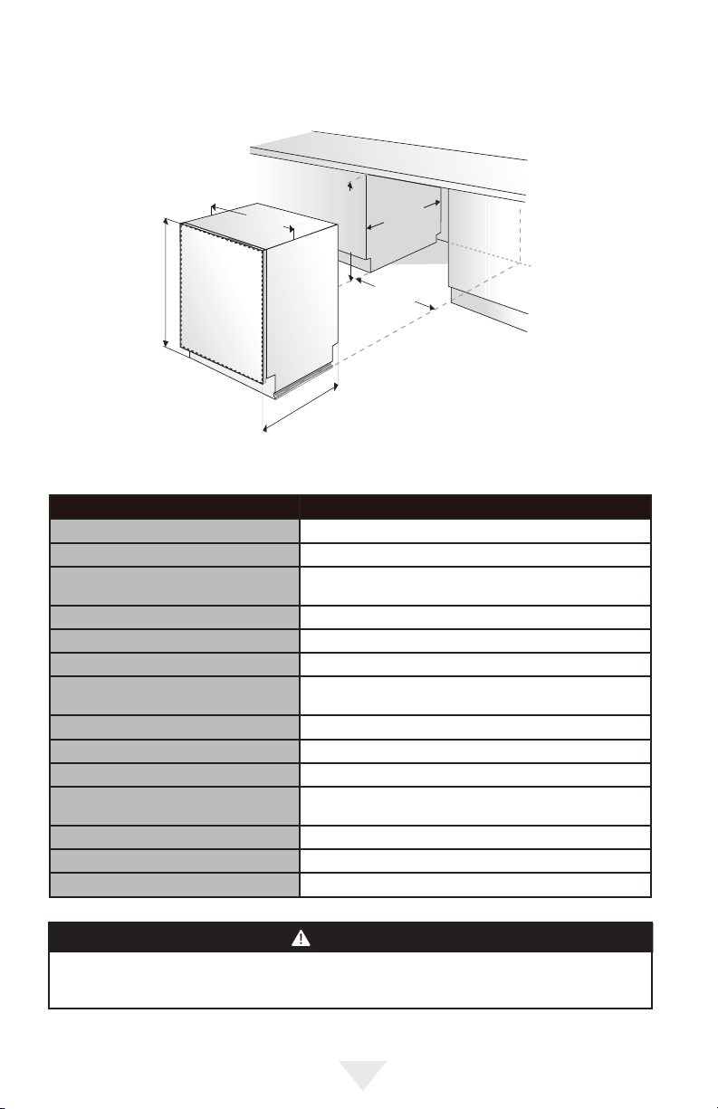
Overall width 23-9/16" (59.8 cm)
Overall height from oor 33-7/8 (86.0 cm) min. to 35-7/8" (91.1 cm) max.
Overall depth from rear
Cutout width 24" (61.0 cm)
Cutout height 34" (86.4 cm) min. to 36" (91.4 cm) max.
Cutout depth 24"(61.0 cm)
Electrical requirement 12.0 amps, 120V/60 Hz; 4' (1.2 m) electrical cord
Water Heating Element Rating 1240 watts
Inlet Water Temperature 120°F (49°C) required
Inlet Water Pressure Operating Range 4.35 to 145 psi (.3 - 10 bar)
Inlet Water Hose Minimum 3/8 OD copper tubing or braided metal water line
Drain Hose 6.4' (1.9 m) drain hose provided
Drain Hose High Loop Required Height from oor – 28" (71.1 cm)
Approx. shipping wt. 97 lbs. (44 kg)
Because we continually strive to improve our products, we may change our specications and design
without prior notice. This device corresponds to the following directives: UL 749 Household Dishwasher
Directive.
without door panel – 21 5/8" (54.9 cm)
with door panel – 22 3/16" (156.4 cm)
supplied with unit
required.
NOTICE
7
Page 8
ENCLOSURE PREPARATION
Electrical Preparation
WARNING
The dishwasher is designed for an electrical supply of 120V, 60Hz, AC, connected to a dishwasherdedicated, properly grounded electrical circuit with a fuse or breaker rated for 15 amperes.
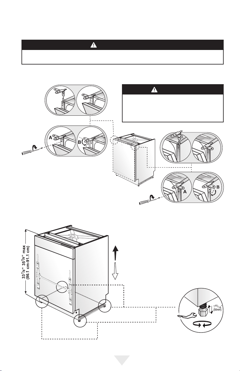
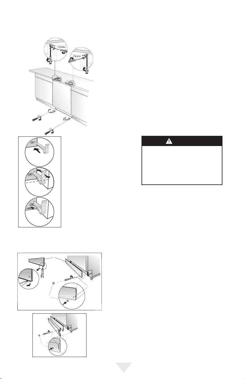
Preparation for Installing Mounting Brackets
WARNING
Dishwasher must be secured to adjacent cabinetry
using the mounting brackets provided. Failure to do
this may cause damage to property or bodily injury.
• Place the two mounting brackets into the top
corners of the dishwasher.
• Fix the mounting brackets (A) to the top
corners of the dishwasher, with the screws
supplied.
• Bend sides of mounting brackets (B) in order
to x from sides (if necessary).
Adjusting Height
If the height of the enclosure is 33-7/8" to 35-7/8"
(86.1cm - 91.1cm), adjust supports as shown in the
gure.
8
Page 9
WARNING
DANGER
CAUTION
WARNING
DANGER
CAUTION
ENCLOSURE PREPARATION
• Adjust the front foot level with the adjusting
wrench to balance and raise the dishwasher to the
enclosure height.
• Adjust the rear foot level with a screwdriver to
balance and raise the dishwasher to the enclosure
height.
NOTICE
Make sure the dishwasher is plumb and notice
dishwasher can be placed with a small clearance
under the counter top.
• Turning the screwdriver in the direction of the
black arrows will bring the dishwasher back feet
up.
• Turning the screwdriver in the direction of the
white arrows will take the dishwasher rear feet
down.
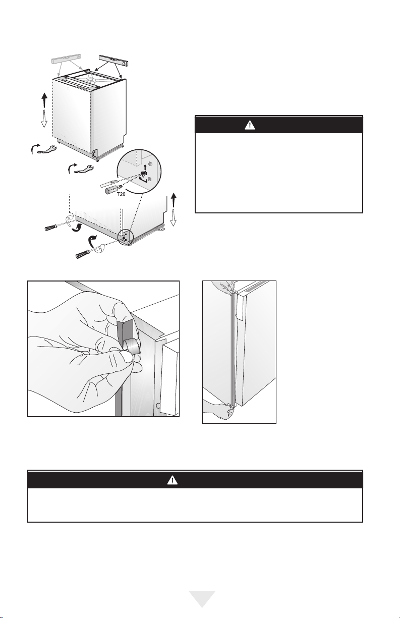
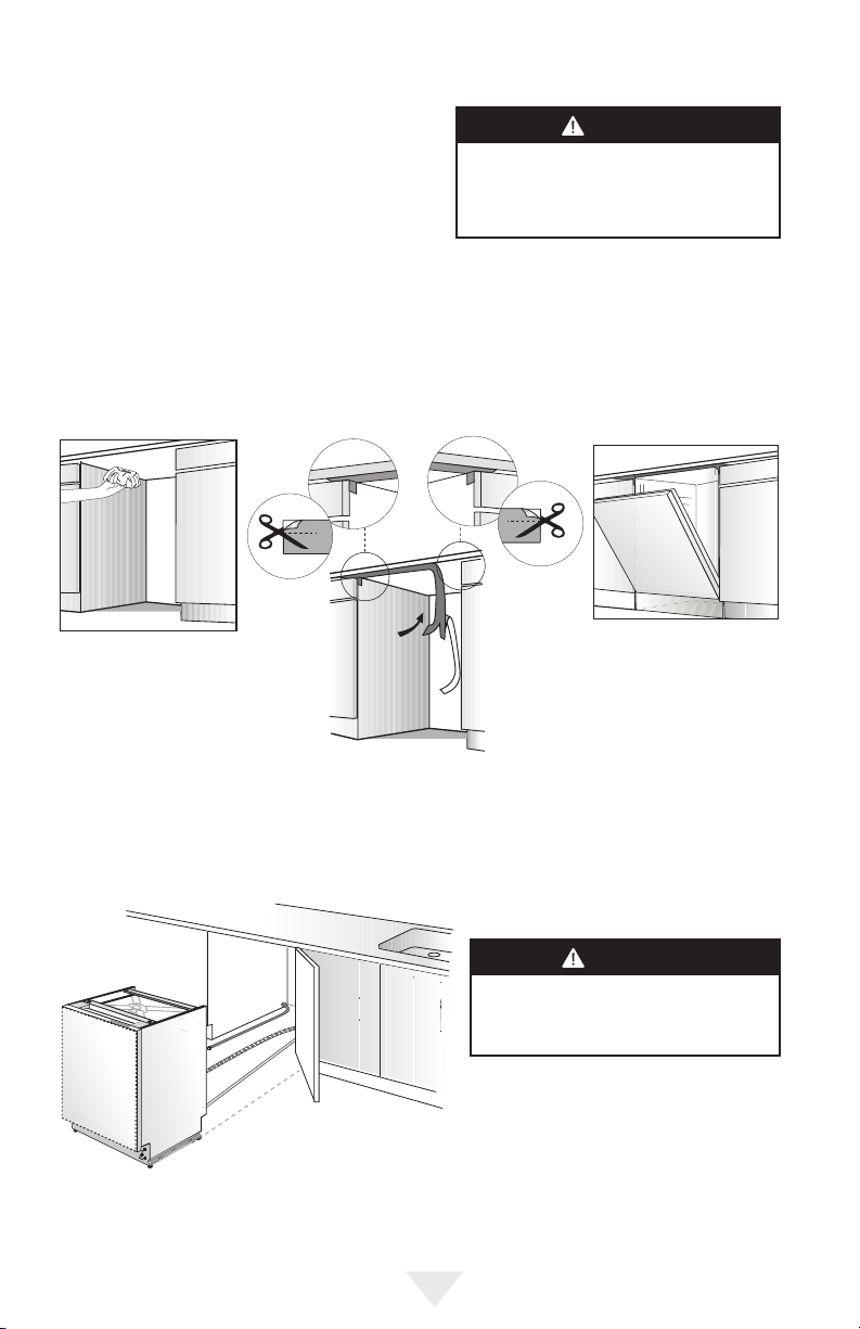
Installing the Side
Trim Strips
• Remove the
adhesive tape
(Figure A).
• Place the trim strips
on the front edge
of the side walls
(Figure B).
NOTICE
Make sure you use the correct trim strip since there is a left and a right side strip. The exible material
should be facing forward (Figure B).
9
Page 10
INSTALLATION PREPARATION
WARNING
DANGER
WARNING
DANGER
CAUTION
WARNING
DANGER
CAUTION
WARNING
DANGER
CAUTION
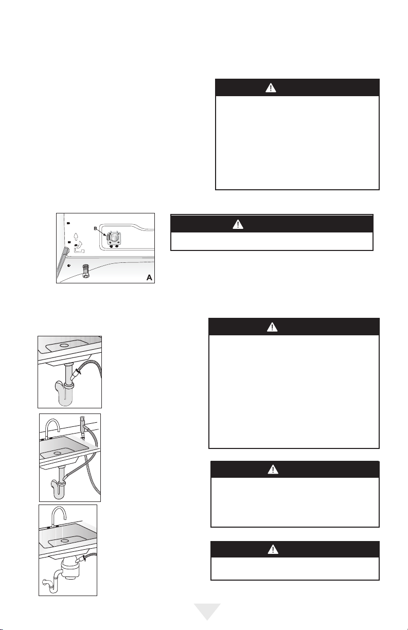
Preparing the Water Connection (A)
• Install an easily accessible shut-off valve (not
supplied) in the water supply line. All solder
connections must be made before the water line
is connected to the dishwasher's water inlet valve.
Water can also be supplied to the dishwasher by
using a exible braided hose line.
• Check with your plumbing supply sources for the
proper hose and 90° elbow and necessary ttings
for the water supply line. This material is not
supplied and must be purchased separately.
Installing the 900 elbow Fitting (B)
Do not overtighten the 90° elbow. Doing so may damage the
water inlet valve and cause a water leak.
If the water supply line is to be copper tubing, make certain that
the elbow has a compression tting. Apply Teon tape or other
pipe sealant when required. Orient the water supply connection
downwards as shown in the gure so the water line can be easily
pulled underneath or on the side of the dishwasher.
WARNING
Installation should be performed by a qualied
installer. Work by unqualied persons could be
dangerous and may void the warranty.
If the dishwasher is installed in a location that
experiences freezing temperatures (e.g. in a
vacation home, cabin, etc.), you must drain
all the water from the dishwasher's interior.
Water system ruptures that occur as a result of
freezing are not covered by warranty.
CAUTION
Drain Preparation
Under the Sink Drain
• Install a Y-branch tail pipe
Installing an Air Gap
• If the local ordinance requires
Disposal
• Remove the drain connection
• Every disposal has a hook-up
(Figure A).
an air gap (Figure B).
plug before attaching the drain
hose from the dishwasher.
for a dishwasher; consult your
disposer manual for correct
connection (Figure C).
NOTICE
• Either one of the above methods must be used or
the dishwasher will not operate properly.
• A hose that attaches to a sink spray can
burst if it is installed on the same water line
as the dishwasher. If your sink has one, it is
recommended that the hose be disconnected and
the hole plugged.
• The total length of the drain hose is 76-3/4"
(1950mm). If a hose extension is required, a
drainage hose of equal quality must be used.
• The maximum length must not exceed 157-1/2"
(4000mm). Otherwise, the cleaning process is
negatively inuenced.
NOTICE
You must add a loop at least 28" (71.1cm) above
the oor of the cabinet and above the drain
connection in the drain hose to prevent waste
water from not draining properly and causing either
poor washing results or a bad odor.
NOTICE
Check with local ordinance for type of air gap
required.
10
Page 11
INSTALLATION PREPARATION
WARNING
DANGER
CAUTION
WARNING
DANGER
CAUTION
Steam Protection Foil
Steam will form inside the dishwasher during operation.
At the end of the cycle, when the dishwasher door is
opened, it is required to use a steam protection foil to
prevent any steam from collecting on the underside of the
counter top.
Steam protection foil must be applied where
the steam escapes when door is rst opened.
Failure to install the steam protection foil
during installation can lead to damage to to
the cabinets and countertop.
NOTICE
Fitting the Protection Foil
• Before applying the steam protection foil to the underside of the countertop, clean the area with a damp
cloth (as shown in Figure A). Once the area dries, apply the steam protection foil.
• The steam protection foil will be applied at the location where the hot steam escapes when you rst open
the door (as shown in Figure B).
Placement of Dishwasher into the Opening
Now place the dishwasher into the opening and get ready to connect all hoses and electrical connections.
Make sure all hoses are pulled through the
side opening of the cabinet, no hoses are
kinked, and all slack is taken out as shown
in the gure to the left.
NOTICE
11
Page 12
INSTALLATION
Drain Hose Connection, Water Supply, and Electrical Connections
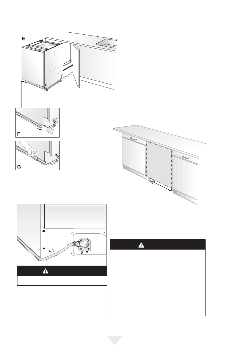
Drain Hose Connection
Connect the drain hose to the drain plumbing.
• Use the supplied rubber connection hose
and drain hose clamps to connect the
dishwasher drain hose to the plumbing drain
connection.
• Use the spring clamp to secure the rubber
connection hose to the dishwasher drain
hose. Use the screw clamp to secure the
rubber connection hose to the plumbing
drain connection.
Note that the marks on the rubber
connection hose should be on the
drain hose side.
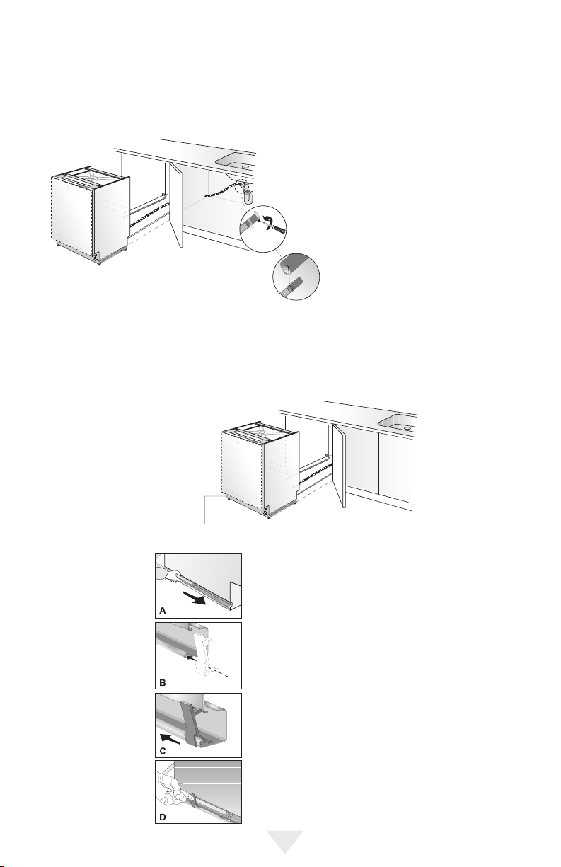
Preparation of Water Supply
Left Side Water Supply Connection
• Before pushing the dishwasher into the cabinet, you
must place water supply hoses into the channel of the
dishwasher (Figure A).
• Place the supplied clips into the channel (Figure B) so
that you can move these clips along the channel (Figure
C) and x by pressing on (Figure D) so that you can
keep the water supply hose in the channel.
12
Page 13
INSTALLATION
WARNING
DANGER
WARNING
DANGER
CAUTION
• After installing one clip for each side, push the
dishwasher into the cabinet (Figure E).
• Note that while pushing the dishwasher into the cabinet, water supply hose
must move in the channel to the front (Figure F).
• Fix the second clip
(Figure G).
NOTICE
After connections are made, turn on the water
supply to check for leaks.
Water supply may be connected to the dishwasher in
one of two ways:
• With metal braided hose.
• With copper tubing.
CAUTION
• Hot water supply line: Use minimum 3/8" O.D. copper tubing or metal braided dishwasher supply line.
• Temperatures required for soldering and sweating
will damage the dishwasher's water inlet valve so if
any such operation is needed, keep the heat source
min. 7-7/8" (20.0cm) away from the dishwasher's
water inlet valve.
• There should not be any sharp bends in the water
line that may restrict the water ow.
• Teon tape or pipe thread compound must be used
for sealing the connection. Before connecting the
copper water supply line to the dishwasher, ush it
with hot water to clear any foreign material.
13
Page 14
INSTALLATION
Electrical Connection
WARNING
• Make sure the voltage and frequency listed on the data plate correspond with the household electrical
supply. This data must correspond to prevent injury and machine damage. Consult a qualied
electrician if in doubt.
• Only connect the dishwasher to the mains when all installation and plumbing work is done.
• DO NOT use any extension cord or portable outlet device to connect the dishwasher to a power
supply.
• The power-supply receptacle for the appliance shall be installed in a cabinet or on a wall adjacent to
the undercounter space in which the appliance is to be installed.
• The access hole of the supply cord to the installation compartment must be smooth and rounded
and it must be large enough for the attachment plug to pass through. The longest dimension of the
opening shall not be more than 1.5" (35mm). If the partition is metal, it needs to be covered with an
edge protector.
• Care must be taken when the appliance is installed or removed, to reduce the likelihood of damage to
the power-supply cord.
Grounding Instructions
This appliance must be grounded. In the event of a malfunction or breakdown, grounding will reduce
the risk of electrical shock by providing a path of least resistance for electrical current. This appliance is
equipped with a cord having an equipment-grounding conductor and a grounding plug. The plug must
be plugged into an appropriate outlet that is installed and grounded in accordance with all local codes
and ordinances. This appliance must be connected to a grounded metal, permanent wiring system, or an
equipment-grounding conductor must be run with the circuit conductors and connected to the equipmentgrounding terminal or lead on the appliance.
WARNING
• Improper connection of the equipment-grounding conductor can result in a risk of electric
shock. Check with a qualied electrician or service representative if you are in doubt whether
the appliance is properly grounded. Do not modify the plug provided with the appliance; if it
will not t the outlet, have a proper outlet installed by a qualied electrician.
14
Page 15
Readjusting Leveling Legs
WARNING
DANGER
CAUTION
INSTALLATION
Now that the dishwasher is in the cabinet, you must
readjust the leveling legs to bring the dishwasher up
to the required height and attach it underneath the
countertop.
• Readjust the front leveling leg with adjusting
wrench to balance the dishwasher and raise it up
under the countertop; make sure the unit is level.
• Readjust the rear leveling leg with a screwdriver to
balance the dishwasher and raise it to the required
height using the brackets supplied.
• Attach the dishwasher underneath the countertop
with the four screws supplied (Ø 1/8"x1/8"-Ø
3.5mmx14mm). Make sure you do not go through
the top of the countertop or damage granite.
Adjusting the Movable Kickplate
Now that you have successfully
installed the dishwasher, you need to
attach the kickplate to the dishwasher.
The two-piece kickplate can be
adjusted to the height and depth
needed for your kitchen. Be sure to
use the slotted kickplate in the front
and the other behind it. They slide into
each other.
1. Insert the movable kickplate
brackets into the channel (A).
2. Make sure that the plastic tab to
the left of the “L" opening on the
dishwasher has not closed the
channel you will push the bracket
through.
3. Now attach the kickplate to
the bracket with the two (Ø
3/16"x1/4"-Ø 4mmx6mm) screws
and the caps provided as follows.
If the enclosure height is below 33-1/16" (84.0cm), use only
(o) labeled kickplate (kickplate without slots). Installation
should be done following the steps illustrated in the Figures
A, B, and C respectively.
1. Bend tabs on kickplate (o) inwards (A).
2. Secure kickplate to brackets with screws (t) as shown in
the supply bags (B).
3. Attach caps (s) as shown in the supply bags (C).
If the enclosure height is above 33-1/16" (84.0cm), use “o"
and “p" labeled kickplates together. Make sure the slotted
kickplate (p) is on the outside so you can adjust height of
the kickplate. Installation should be done following the steps
illustrated in the gures A, B, and C respectively.
1. Align the kickplate (o) and (p) (A).
2. Secure kickplates to brackets with screws (t) after
adjusting the height of the slotted kickplate (p) (B).
3. Attach caps (s) as shown in the supply bags (C).
NOTICE
There is a left and a right bracket.
• Adjust the kickplate brackets forward or
backwards so that they will align with
the kitchen kickplate (B).
• Lock the kickplate brackets as shown
with the plastic tab on the dishwasher
into the teeth of the bracket (C).
15
Page 16

INSTALLER CHECKLIST AND FINAL INSTRUCTIONS
Your installer must have completed and checked the following:
□ The dishwasher is square and level.
□ The dishwasher is fastened securely to the cabinetry.
□ The dishwasher door opens and closes freely. The dishwasher door must close without hitting any
cabinetry or countertop.
□ The inlet water supply is turned on and checked for leaks.
□ The drain hose has been connected and checked for leaks. There must be no kinks or obstructions in
the drain hose.
□ The drain hose must be installed with a 28" (710mm) high drain loop for drain hook-ups without any air
removed.
□ If the dishwasher drain is hooked up to a garbage disposal, the drain hopper plug must be removed.
□ The spray arms are free and rotate freely.
□ The rinse cycle has been run.
□ The water level will be below the lter screen after the end of the wash program. It is normal to nd
some water in the drain lter area.
□ Set the water softener to the correct water hardness for your area. If the dishwasher drain is connected
to a garbage disposal, make sure that the drain/hopper plug has been removed.
Final Instructions
• Press the On/Off button to turn the dishwasher on.
• Power indicator light comes on.
• Use the Program Select button to choose a washing program.
• Start the program with the Start/Pause/Cancel button.
• Run the dishwasher through one complete cycle. When the wash cycle is completed, use the On/Off
button to turn the dishwasher off.
Self-Help Hints
The screen does not come on:
• Check to make sure the breaker to the dishwasher is in the on position.
• Check to make sure that the supply cord is plugged.
No water is coming into the dishwasher:
• Check to make sure the hot water shut-off is in the ON position.
Water does not drain:
• Make sure drain hose is not kinked or comes out of air gap next to the sink.
• Remove drain hose from disposal making sure plug is removed.
16
Page 17

SERVICE & REGISTRATION
Only authorized replacement parts may be used in performing service on the appliance. Do not repair or
replace any part of the appliance unless specically recommended in the manual. All servicing should be
referred to a qualied technician.
Contact AGA Marvel by calling 1-800-223-3900, for the nearest service parts distributor in your area or write
to:
AGA Marvel
1260 E. VanDeinse St.
Greenville, MI 48838
The serial number and model number for your dishwasher are located on the identication plate mounted
on the right side of the inner door.
Record the following information indicated below. You will need it if service is ever required.
Model number _____________________ Serial number ___________________________________
Date of purchase ___________________________ Date installed ___________________________
Dealer's name ________________________________________________________________________
Address ____________________________________________________________________________
___________________________________________________________________________________
These installation instructions should remain with the dishwasher for future reference.
17
Page 18

1260 E. Van Deinse St.
Greenville MI 48838
800.223.3900
41014835-EN Rev B
1/19/18
www.agamarvel.com
All specications and product designs subject to
change without notice. Such revisions do not entitle
the buyer to corresponding changes, improvements,
additions, replacements or compensation for
previously purchased products.
Page 19

GUIDE
D’INSTALLATION
Lave-vaisselle
intégré
AELTTDW
ALTTDW
AMCTTDW
AMPROTTDW
HCTTDW
Page 20

TABLE DES MATIÈRES
Consignes de sécurité importantes ........................................................................................3
Outils pouvant s’avérer nécessaires.......................................................................................4
Matériels pouvant s’avérer nécessaires .................................................................................5
Matériels fournis .....................................................................................................................6
Pièces fournies ...............................................................................................................6
Spécications du lave-vaisselle ..............................................................................................7
Préparation de l’armoire .........................................................................................................8
Installation des tringles de nissage latérales ........................................................................9
Préparation du raccordement d’eau .......................................................................................10
Préparation de la vidange ...............................................................................................10
Feuille de protection contre la vapeur ....................................................................................11
Installation ..............................................................................................................................12
Raccordement du exible de vidange, prise d’eau et raccordements électriques ..........12
Préparation de l’approvisionnement en eau ...................................................................12
Raccordements électriques ....................................................................................................14
Réajustement de l’aplomb latéral de pied ..............................................................................15
Réglage du garde-pieds mobile..............................................................................................15
Liste de contrôle de l’installateur ............................................................................................16
Dernières instructions .............................................................................................................16
Entretien et enregistrement ....................................................................................................17
2
Page 21

IMPORTANT –VEUILLEZ LIRE ET SUIVRE
AVERTISSEMENT
DANGER
AT TENTION
REMARQUE
AVERTISSEMENT
DANGER
AVERTISSEMENT
DANGER
AT TENTION
AVERTISSEMENT
DANGER
AT TENTION
AVERTISSEMENT
DANGER
AT TENTION
• Lisez entièrement et avec attention ce manuel d’installation et les consignes de sécurité en particulier. Ils
vous permettront de gagner du temps et des efforts et vous aideront à assurer la performance optimale
du lave-vaisselle.
• Assurez-vous de respecter tous les avertissements et les mises en garde indiqués. Recherchez particu-
lièrement les icônes ayant des points d’exclamation à l’intérieur. L’icône information fournit également des
références importantes.
AVERTISSEMENT
Indique une situation potentiellement dangereuse
qui, si elle n’est pas évitée,
peut entraîner la mort ou de graves blessures.
Indique une situation potentiellement dangereuse
qui, si elle n’est pas évitée, peut endommager
le lave-vaisselle, la vaisselle, l’équipement ou
l’environnement.
AT TENTION
Indicates a potentially hazardous situation
Indique une situation potentiellement dangereuse
qui, si elle n’est pas évitée,
peut entraîner des blessures. Elle peut également
être utilisée pour alerter contre les pratiques non
sécurisées.
Outre ces instructions, le lave-vaisselle doit être
installé :
• Conformément à tous les codes locaux ou en
l’absence d’un code local,
•Aux États-Unis conformément au code national
d’électricité,
•Au Canada, conformément au code canadien
d’électricité C22.1-dernière édition/codes provin-
ciaux et municipaux et/ou codes locaux.
REMARQUE
L’installation doit être effectuée par un
plombier, un entrepreneur ou un installateur
formé, agrée et assuré. Toute installation
effectuée par des personnes autres que celles
indiquées, peut déboucher sur une installation
inappropriée et des dégâts matériels.
REMARQUE
Mettez au rebut les sacs ou articles fournis
avec l’emballage d’origine uniquement à la n
de toute l’installation.
Préparation du site
Il est recommandé de procéder à une inspection minutieuse du site
AVANT le dépotage et le déplacement de l’appareil.
Lors de l’installation du lave-vaisselle, suivez les mesures de précautions de base notamment :
• Seul un représentant agrée du service d’entretien peut assurer la conversion du lave-vaisselle de
raccordement par cordon à raccordement dénitif.
• L’installation et la réparation doivent être effectuées uniquement par un installateur qualié. L’exécution de
travaux par des personnes non qualiées peut s’avérer dangereuse et annuler la garantie.
• Installez le exible de vidange du lave-vaisselle à l’aide d’une boucle de vidange à 710 mm (28") au
moins du plancher de l’armoire, au risque de ne pas vidanger correctement le lave-vaisselle.
• Ce lave-vaisselle est conçu pour un usage résidentiel uniquement et ne doit pas être utilisé dans les
établissements commerciaux.
• Installation neuve : Si le lave-vaisselle est une installation neuve, effectuez la plupart des travaux avant
de poser le lave-vaisselle.
• Remplacement : S’il s’agit du remplacement du lave-vaisselle,vériez les anciens raccordements du lave-
• Inspection du lave-vaisselle : Après le dépotage du lave-vaisselle et avant son installation, inspectez
Pour nous contacter, vous pouvez appeler notre numéro gratuit au 1-800-223-3900 ou nous contacter via
le site Web
www.agamarvel.com
vaisselle pour vous assurer de la compatibilité et remplacez les pièces si nécessaire.
minutieusement le lave-vaisselle à la recherche d’éventuels dommages dus au transport ou de défauts de
fabrication apparents. Signalez immédiatement tout dommage.
REMARQUE
3
Page 22

IMPORTANT - VEUILLEZ LIRE ET SUIVRE
• N’U TILISEZ PAS l’appareil s’il est endommagé, défectueux, partiellement démonté ou s’il comporte des
pièces manquantes ou cassées.
• Suivez également les consignes de sécurité contenues dans le guide d’utilisation et d’entretien.
• Pour réduire le risque de choc électrique, d’incendie ou de blessure corporelle, l’installateur doit s’assurer
que le lave-vaisselle est complètement fermé au moment de l’installation.
• Branchez le lave-vaisselle à l’alimentation électrique uniquement lorsque tous les travaux d’installation et
de plomberie sont terminés.
• Si le lave-vaisselle est installé dans un lieu où les températures peuvent entraîner le gel (par ex. dans une
maison de vacances, une cabine, etc.), vous devez vidanger toute l’eau contenue à l’intérieur du lavevaisselle. Les coupures d’eau qui se produisent à cause du gel ne sont pas couvertes par la garantie.
• Fixez le lave-vaisselle à l’armoire attenante à l’aide des supports fournis. Tout manquement à cette règle
peut entraîner des dégâts matériels ou des blessures corporelles.
• Branchez l’appareil à un circuit d’alimentation électrique à la puissance nominale appropriée,
correctement protégé et à la dimension appropriée pour éviter toute surcharge électrique. Le lavevaisselle est conçu pour une alimentation électrique CA de 120 V (volts), 60 Hz (hertz), raccordée à un
circuit électrique spécialisé pour lave-vaisselle et correctement mis à la terre à l’aide d’un fusible ou de
disjoncteurs de 15 ampères. Les conducteurs d’alimentation électrique doivent être en l de cuivre de #16
AWG minimum de 167°F (75°C) ou supérieur. Respectez ces exigences pour éviter toute blessure et des
dommages à la machine. Consultez un électricien qualié si vous avez des doutes.
• N’U TILISEZ ni rallonge ni prise portable pour brancher le lave-vaisselle à l’alimentation électrique.
• Assurez-vous que tous les emballages et sacs plastiques, petites pièces, etc. sont mis au rebut en toute
sécurité et tenus à distance des enfants. Risque d’étouffement!
• Déposez la porte du lave-vaisselle lors de la mise hors service d’un vieux lave-vaisselle ou de sa mise au
rebut. Assurez-vous que l’appareil ne présente aucun danger pour les enfants lors de l’entreposage pour
la mise au rebut.
• Les vieux appareils peuvent contenir du matériel recyclable. Contactez les autorités responsables du
recyclage dans votre localité sur la possibilité de recycler ce matériel.
INFORMATIONS GÉNÉRALES
Outils pouvant s’avérer nécessaires
Clé à tuyau Coupe-l Perceuse
Scie-cloche Marteau Pince à dénuder
Ruban à mesurer Tournevis Torx (T20) Tournevis Phillips
Clé à molette Tournevis à entaille Ciseaux
Niveau Brosse Crayon
4
Page 23

INFORMATIONS GÉNÉRALES
Matériels pouvant s’avérer nécessaires
Conduite d’approvisionnement en eau chaude – Tube en cuivre
de 3/8 po. O.D. au minimum ou conduite d’approvisionnement
du lave-vaisselle en métal torsadé.
Coude de 90° avec letages N.P.T. mâles de 3/8 po. sur une tige,
dimensionné pour s’adapter à votre conduite d’approvisionnement
en eau (tube en cuivre/raccord à compression ou tuyau tressé) sur
l’autre tige.
Raccord de conduit ou serre-câble homologué par l’UL.
Ruban Téon ou tout autre composé de letage de tuyau pour
assurer l’étanchéité des raccordements de plomberie.
Robinet d’arrêt et raccords adaptés à la conduite d’approvisionnement
en eau chaude (tube en cuivre/raccord à compression ou tuyau tressé).
Silicone
Colle
5
Page 24

INFORMATIONS GÉNÉRALES
Pièces fournies
Les pièces du lave-vaisselle sont livrées dans plusieurs sacs plastiques. Vériez les sacs de pièces pour
vous assurer de disposer de toutes les pièces indiquées ci-dessous.
Matériels fournis
Pièces du lave-vaisselle Sac 1
Ce sac contient les pièces suivantes à la
livraison :
a. Tringles de nissage latérales – gauche
b. Tringles de nissage latérales – droit
c. Clé de réglage
d. Vis Ø 3,5 mm x 14 mm (Ø 1/8 po. x 5/8
po.)
e. Support de xation – gauche
f. Support de xation – droit
g. Pince à ressort
h. Vis de serrage
j. Connecteur en caoutchouc
k. Support de garde-pieds – gauche
l. Support de garde-pieds – droit
m. Protecteur de bord
n. Pinces
o. Garde-pieds (garde-pieds sans fente)
p. Garde-pieds
r. Vis Ø 3,9 mm x 9 mm (Ø 1/8 po. x 3/8
po.)
s. Bouchons plastiques
t. Vis Ø 4 mm x 6 mm (Ø 3/16 po. x 1/4
po.)
z. Feuille de protection contre la vapeur
Pièces du lave-vaisselle Sac 2
v. Vis Ø 3,5 mm x 14 mm
(Ø 1/8 po. x5/8 po.)
y. Vis Ø 4 mm x 43 mm
(Ø 3/16 po. x1-3/4 po.)
Pièces xées à l’arrière
du lave-vaisselle
a. Tringles de nissage
latérales – gauche
b. Tringles de nissage
latérales – droit
o. Garde-pieds (garde-
pieds sans fente)
p. Garde-pieds
6
Page 25

SPECIFICATIONS
24” max
(61.0 cm max
AVERTISSEMENT
DANGER
AT TENTION
24” max
(61.0 cm max)
24” max
(61.0 cm max)
)
Lave-vaisselle intégré
Largeur totale 23-9/16" (59.8 cm)
Hauteur totale à partir du sol 33-7/8 (86.0 cm) min. to 35-7/8" (91.1 cm) max.
Profondeur totale depuis l’arrière
Largeur de découpe 24" (61.0 cm)
Hauteur de découpe 34" (86.4 cm) min. to 36" (91.4 cm) max.
Profondeur de découpe 24" (61.0 cm)
Exigences en matière d’électricité 12.0 amps, 120V/60 Hz; 4’ (1.2 m) cordon électrique
Caractéristiques nominales de ’élément de
chauffage de l’eau
Température de l’eau à l’arrivée 120°F (49°C) required
Pression de l’eau à l’arrivée Plage de
fonctionnement
Flexible d’arrivée d’eau Tube de cuivre OD de 3/8" au minimum ou conduite
Flexible d’évacuation exible d’évacuation de 1,9 m (6,4 pieds) fourni
Flexible d’évacuation à grande boucle exigé Hauteur à partir du sol – 28" (71.1 cm)
Poids d’expédition approximatif 97 livres (44 kg)
sans le panneau de porte– 21 5/8" (54.9 cm)
avec le panneau de porte – 22 3/16" (156.4 cm)
fourni avec l’équipement
1240 watts
4.35 to 145 psi (.3 - 10 bar)
d’eau en métal torsadé exigé.
REMARQUE
En raison des efforts continus que nous fournissons pour l’amélioration de nos produits, nous pouvons
modier nos spécications et les modèles sans avis préalable. Cet appareil correspond aux directives
suivantes : Directive UL 749 sur les lave-vaisselle domestiques.
7
Page 26

PRÉPARATION DE L’ARMOIRE
Préparation électrique
Le lave-vaisselle est conçu pour une alimentation électrique CA
de 120 V, 60 Hz, raccordée à un circuit électrique spécialisé pour
lave-vaisselle et correctement mis à la terre à l’aide d’un fusible ou
de disjoncteurs de 15 ampères.
AVERTISSEMENT
Préparation pour l’installation de supports de xation
AVERTISSEMENT
Fixez le lave-vaisselle à l’armoire attenante à l’aide
des supports de xation fournis. Tout manquement à
cette règle peut entraîner des dégâts matériels ou des
blessures corporelles.
• Placez les deux supports de xation dans les coins supérieurs.
• Fixez les supports de xation (A) aux coins supérieurs du lave-vaisselle à l’aide des vis fournies.
• Pliez les côtés des supports de xation (B) pour sécuriser les côtés (si nécessaire).
Réglage de la hauteur
Si la hauteur de l’armoire est de 86,1
cm-91,1 cm (33-7/8 po à 35-7/8 po),
po. max
8
/
7
po. 35
8
/
7
(86.1 cm-91.1 cm)
33
ajustez les supports tel que l’illustre la
gure.
8
po.
Page 27

PRÉPARATION DE L’ARMOIRE
AVERTISSEMENT
DANGER
AT TENTION
AVERTISSEMENT
DANGER
AT TENTION
• Réglez le niveau de pied avant à l’aide de la clé de
réglage pour équilibrer et soulever le lave-vaisselle à la
hauteur de l’armoire.
• Ajustez le niveau de pied arrière à l’aide d’un tournevis
pour équilibrer et soulever le lave-vaisselle à la hauteur
de l’armoire.
REMARQUE
• Assurez-vous que le lave-vaisselle est vertical et
notez qu’il est possible de l’installer en laissant un
petit écart sous le comptoir de cuisine.
• Tourner le tournevis dans le sens des èches noires
soulève les pieds du lave-vaisselle.
• Tourner le tournevis dans le sens des èches
blanches rabaisse les pieds du lave-vaisselle.
Installation des tringles de nissage
latérales
• Enlevez le ruban adhésif (Figure A).
• Placez les tringles de nissage latérales
sur l’extrémité avant des parois latérales
(Figure B).
REMARQUE
Assurez-vous d’utiliser la tringle de nissage appropriée vu qu’il y a une tringle
latérale gauche et droite. Orientez le
matériel exible vers l’avant (Figure B).
9
Page 28

PRÉPARATION DE L’INSTALLATION
AVERTISSEMENT
DANGER
AVERTISSEMENT
DANGER
AT TENTION
AVERTISSEMENT
DANGER
AT TENTION
AVERTISSEMENT
DANGER
AT TENTION
Préparation du raccordement d’eau (A)
• Installez un robinet d’arrêt facilement accessible (non
fourni) dans la conduite d’approvisionnement en eau.
Effectuez tous les raccordements soudés avant de
raccorder la conduite d’eau à la vanne d’alimentation
en eau du lave-vaisselle. Le lave-vaisselle peut
également être alimenté en eau à l’aide d’une
conduite de tuyau souple tressé.
• Consultez vos fournisseurs en plomberie pour
connaître le tuyau approprié et le coude de 90°
ainsi que les raccords nécessaires pour la conduite
d’approvisionnement en eau. Ce matériel n’est pas
fourni et doit être acheté séparément.
Installation du raccord de coude de 90° (B)
Ne serrez pas trop le coude de 90°, au risque d’endommager
la vanne d’alimentation en eau et de provoquer une fuite
d’eau.
Si la conduite d’approvisionnement en eau prévue est en tube
de cuivre, assurez-vous que le coude comporte un raccord à
compression. Appliquez du ruban Téon ou tout autre produit
d’étanchéité pour tuyau si nécessaire. Orientez le raccordement d‘alimentation en eau vers le bas tel que l’illustre la gure,
pour que la conduite d’eau puisse passer aisément sous ou sur
Préparation de la vidange
Sous le exible ’évacuation
de l’évier
• Installez un tuyau
d’aspiration avec
branchement en Y
(Figure A).
Installation de l’intervalle
d’air
• Si la réglementation locale
exige l’installation d’un
intervalle d’air (Figure B).
Mise au rebut
• Déposer le bouchon de
raccordement de l’évacuation
avant de xer le exible
d’évacuation du lave-vaisselle.
• Chaque broyeur à ordures
dispose d’un raccordement
pour le lave-vaisselle,
consultez le manuel de votre
broyeur à déchets pour
connaître le raccordement
approprié (Figure C).
le côté du lave-vaisselle.
• Utilisez l’une des méthodes ci-dessus pour que la
machine fonctionne correctement.
• Un exible relié à une douchette peut exploser s’il
est installé sur la même conduite d’eau que le lavevaisselle. Si votre évier est équipé d’une douchette,
il est recommandé de déconnecter le exible et de
boucher le trou.
• La longueur totale du exible d’évacuation est
de 1950 mm (76-3/4 po.). Si une rallonge est
nécessaire, utilisez un exible d’évacuation de
qualité identique.
• La longueur maximale ne doit pas dépasser
4000 mm (157-1/2 po.), au risque d’affecter
négativement le processus de nettoyage.
Vous devez ajouter une boucle d’au moins 71,1cm
(28") au-dessus du plancher de l’armoire et audessus du raccordement du exible d’évacuation
pour faciliter l’évacuation appropriée des eaux usées
et éviter un mauvais nettoyage ou de mauvaises
odeurs.
Consultez la réglementation locale pour connaître le
type d’intervalle d’air requis.
AVERTISSEMENT
L’installation doit être effectuée par un
installateur qualié. L’exécution de travaux par
des personnes non qualiées peut s’avérer
dangereuse et annuler la garantie.
Si le lave-vaisselle est installé dans un lieu où
les températures peuvent entraîner le gel (par
ex. dans une maison de vacances, une cabine,
etc.), vous devez vidanger toute l’eau contenue
à l’intérieur du lave-vaisselle. Les coupures
d’eau qui se produisent à cause du gel ne sont
pas couvertes par la garantie.
AT TENTION
REMARQUE
REMARQUE
REMARQUE
10
Page 29

PRÉPARATION DE L’INSTALLATION
AVERTISSEMENT
DANGER
AVERTISSEMENT
DANGER
Feuille de protection contre la vapeur
La vapeur se forme à l’intérieur du lave-vaisselle
pendant le fonctionnement. À la n du cycle, lorsque
vous ouvrez la porte du lave-vaisselle, il est exigé
d’utiliser une feuille de protection contre la vapeur pour
éviter l’accumulation de la vapeur sous le comptoir de
cuisine.
Insertion de la feuille de protection
• Avant d’appliquer la feuille de protection contre la vapeur au bas du comptoir de cuisine, nettoyez la zone
à l’aide d’un torchon humide (tel que l’illustre la Figure A). Une fois la zone asséchée, appliquez la feuille
de protection contre la vapeur.
• La feuille de protection contre la vapeur est appliquée à l’endroit où la vapeur chaude s’échappe lorsque
vous ouvrez la porte (tel que l’illustre la Figure B).
Appliquez la feuille de protection contre la
vapeur à l’endroit où elle s’échappe lorsque
vous ouvrez d’abord la porte. Si la feuille de
protection contre la vapeur n’est pas posée
lors de l’installation, cela peut endommager les
armoires et le comptoir de cuisine.
AT TENTION
Pose du lave-vaisselle dans l’ouverture
Installez à présent le lave-vaisselle dans l’ouverture et soyez prêt à brancher tous les exibles et les
raccordements électriques.
AT TENTION
Assurez-vous que tous les exibles
11
sortent à travers l’ouverture latérale de
l’armoire, qu’aucun exible n’est plié et
tous les relâchements sont éliminés tel
que l’illustre la gure de gauche.
Page 30

INSTALLATION
Raccordement du exible d’évacuation, de l’approvisionnement en eau, et
raccordements électriques
Préparation de l’approvisionnement en eau
Raccordement du exible d’évacuation
• Utilisez le raccordement de caoutchouc fourni et
les colliers de serrage du exible d’évacuation pour
brancher le exible d’évacuation du lave-vaisselle
au raccordement de la plomberie d’évacuation.
• Utilisez la pince à ressort pour xer le exible
de raccordement en caoutchouc au exible
d’évacuation du lave-vaisselle. Utilisez la vis de
serrage pour xer le exible de raccordement
en caoutchouc au raccordement de la plomberie
d’évacuation.
Notez que les marques sur le exible de
raccordement en caoutchouc doivent être sur le
côté du exible d’évacuation.
Approvisionnement en eau côté gauche Raccordement
• Avant de pousser le lave-vaisselle dans l’armoire, vous devez placer les
exibles d’approvisionnement en eau dans le montant du lave-vaisselle
(Figure A).
• Posez les attaches fournies dans le montant (Figure B) an de pouvoir
les déplacer le long du montant (Figure C) et xez-les en appuyant
dessus (Figure D) pour maintenir le exible d’alimentation en eau dans le
montant.
12
Page 31

INSTALLATION
AVERTISSEMENT
DANGER
AVERTISSEMENT
DANGER
AT TENTION
• Après l’installation d’une attache sur chaque
côté, poussez le lave-vaisselle dans l’armoire
(Figure E).
• Notez que lorsque vous poussez le lave-vaisselle dans l’armoire, le exible
d’approvisionnement en eau doit se déplacer vers l’avant dans le montant
(Figure F).
• Fixez la deuxième
attache (Figure G).
REMARQUE
After connections are made, turn on the water
supply to check for leaks.
Le raccordement de l’alimentation en eau au lave-
vaisselle peut s’effectuer de l’une des deux méthodes
suivantes :
• à l’aide du tuyau de métal tressé
• à l’aide du tube de cuivre.
AT TENTION
• Conduite d’approvisionnement en eau chaude
: Utilisez un tube de cuivre O.D. de 3/8 po.
minimum ou une conduite d’approvisionnement
pour lave-vaisselle en métal tressé.
• Les températures exigées pour le brasage et le
soudage endommagent la vanne d’alimentation
en eau, par conséquent si l’une de ces opérations
est nécessaire, maintenez la source de chaleur à
20 cm (7-7/8 po.) min de la vanne d’alimentation
en eau.
• La conduite d’eau ne doit avoir aucun pli
susceptible de réduire le débit de l’eau.
• Utilisez du ruban Téon ou un composé
de letage de tuyau pour colmater le
raccordement. Avant de raccorder la conduite
d’approvisionnement en eau au lave-vaisselle,
rincez-la à l’eau chaude pour éliminer tous les
corps étrangers.
13
Page 32

INSTALLATION
Raccordement électrique
AVERTISSEMENT
• Assurez-vous que la tension et la fréquence indiquées sur la plaque d’identication correspondent à
l’alimentation électrique domestique. Ces données doivent correspondre pour éviter des blessures et
l’endommagement de la machine. Consultez un électricien qualié si vous avez des doutes.
• Branchez le lave-vaisselle à la prise secteur uniquement à la n des travaux d’installation et de
plomberie.
• N’U TILISEZ ni rallonge ni prise portable pour brancher le lave-vaisselle à l’alimentation électrique.
• Installez la prise de courant de l’appareil dans une armoire ou sur un mur attenant à l’espace
encastrable dans lequel l’appareil sera installé.
• Le trou d’accès du cordon d’alimentation au compartiment de l’installation doit être lisse, arrondi et
sufsamment large pour que la prise de branchement puisse passer à travers. La dimension la plus
longue de l’ouverture ne doit pas être supérieure à 35 mm (1,5"). Si la partition est en métal, elle doit
être recouverte d’une protection de rive.
• Faites preuve de prudence lors de l’installation ou du retrait de l’appareil pour réduire le risque de
dommage du cordon d’alimentation.
Consignes de mise à la terre
Cet appareil doit être mis à la terre. En cas de dysfonctionnement ou de panne, la mise à la terre réduit le
risque de choc électrique en fournissant un chemin de résistance moindre pour le courant électrique. Cet
appareil est équipé d’un cordon doté d’un conducteur de protection et d’une prise de mise à la terre. La
che doit être branchée à une prise appropriée, installée et mise à la terre conformément à tous les codes
et règlements. Branchez cet appareil à un circuit de câblage métallique et dénitif ou utilisez un conducteur
de protection avec des conducteurs de circuit connectés à une borne de protection ou à un l de mise à la
terre de l’équipement sur l’appareil.
AVERTISSEMENT
• Le raccordement inapproprié du conducteur de protection peut entraîner un risque de choc
électrique. Consultez un électricien qualié ou un représentant du service d’entretien si vous
avez des doutes sur la mise à la terre appropriée de l’appareil. Ne modiez pas la che
fournie avec l’appareil, si elle ne convient pas à la prise, demandez à un électricien qualié
d’installer une prise appropriée.
14
Page 33

INSTALLATION
AVERTISSEMENT
DANGER
AT TENTION
Réajustement des pattes de nivellement
Réglage du garde-pieds mobile
À présent que vous avez réussi à installer le
lave-vaisselle, vous devez xer le garde-pieds
au lave-vaisselle. Le garde-pieds à deux
pièces peut être ajusté à la hauteur et à la
profondeur nécessaires pour votre cuisine.
Assurez-vous d’utiliser le garde-pieds à fente
à l’avant et l’autre à l’arrière. Ils coulissent l’un
dans l’autre.
1. Insérez les supports du garde-pieds mobile
dans le montant (A).
2. Assurez-vous que la languette plastique
à gauche de l’ouverture en “L" sur le
lave-vaisselle ne ferme pas le montant au
travers duquel vous passez le support.
3. Fixez maintenant le garde-pieds au support
à l’aide de deux (Ø 3/16 po.x1/4 po.-Ø 4
mm x 6 mm) vis et des bouchons fournis
comme suit.
Maintenant que le lave-vaisselle est installé dans
l’armoire, vous devez réajuster les pattes de
nivellement pour le surélever jusqu’à la hauteur
requise et le xer en dessous de l’armoire de
cuisine.
• Réajustez la patte de nivellement avant à l’aide
d’une clé de réglage pour équilibrer le lave-
vaisselle et le surélever du dessous de l’armoire
de cuisine ; assurez-vous que l’équipement est
à niveau.
• Réajustez la patte de nivellement arrière à l’aide
d’un tournevis pour équilibrer le lave-vaisselle
et le soulever à la hauteur requise à l’aide des
supports fournis.
• Fixez le lave-vaisselle au-dessous de l’armoire
de cuisine à l’aide des quatre vis fournies (Ø
3,5 mm x 14 mm -Ø 1/8 po. x1/8 po.). Assurez-
vous de ne pas passer en travers le dessus de
l’armoire de cuisine et d’éviter d’endommager le
granit.
REMARQUE
Il est prévu un support gauche
et droit.
• Ajustez les supports du
garde-pieds vers l’avant ou
l’arrière an qu’ils soient
alignés avec le garde-pieds de
la cuisine (B).
• Bloquez les supports du
garde-pieds tel qu’illustré avec
la languette plastique sur le
lave-vaisselle entre les dents
du support (C).
SI la hauteur de l’armoire est inférieure à 84 cm (33-1/16 po.), utilisez
uniquement le garde-pieds étiqueté (o) (garde-pieds sans fente). Précédez à l’installation en suivant les étapes illustrées sur les Figures A, B
et C respectivement.
1. Pliez les languettes sur le garde-pieds (o) vers l’intérieur (A).
2. Fixez le garde-pieds aux supports à l’aide de vis (t) tel qu’illustré sur
les sacs de livraison (B).
3. Fixez les bouchons (s) tel qu’indiqué sur les sacs de livraison (C).
Si la hauteur de l’armoire est supérieure à 84 cm (33-1/16 po.), utilisez
ensemble les garde-pieds étiquetés “o" et “p". Assurez-vous que le
garde-pieds à fente (p) se trouve à l’extérieur pour que vous puissiez
ajuster la hauteur du garde-pieds. L’installation doit s’effectuer en suivant les étapes illustrées sur les gures A, B et C respectivement.
1. Alignez le garde-pieds (o) et (p) (A).
2. Fixez les garde-pieds aux supports à l’aide de vis (t) après le réglage
du garde-pieds à fentes (p) (B).
3. Fixez les bouchons (s) tel qu’indiqué sur les sacs de livraison (C).
15
Page 34

LISTE DE CONTRÔLE DE L’INSTALLATEUR ET DERNIÈRES
INSTRUCTIONS
Your installer must have completed and checked the following:
□ Le lave-vaisselle est carré et à niveau.
□ Le lave-vaisselle est solidement xé à l’armoire.
□ La porte du lave-vaisselle s’ouvre et se referme librement. La porte du lave-vaisselle doit se refermer
sans toucher le coffret ou l’armoire de cuisine.
□ L’arrivée d’eau est activée et son étanchéité vériée.
□ Le exible d’évacuation est raccordé et son étanchéité vériée. Le exible d’évacuation ne doit pas être
plié ni obstrué.
□ Le exible d’évacuation doit être installé avec une grande boucle de vidange de 710 mm (28") pour les
raccordements à la vidange sans fuite d’air.
□ Si le lave-vaisselle est raccordé à un broyeur de déchets, déposez le bouchon de la fosse d’évacuation.
□ Les bras gicleurs sont libres et pivotent en toute liberté.
□ Le cycle de rinçage a été exécuté.
□ Le niveau d’eau est inférieur au tamis à la n du programme de lavage. Il est normal de trouver un peu
d’eau dans la zone du ltre de drain.
□ Réglez l’adoucisseur d’eau au niveau de la dureté appropriée de l’eau de votre région. Si le exible
d’évacuation du lave-vaisselle est raccordé à un broyeur de déchets, assurez-vous de déposer le
bouchon de l’évacuation/de la fosse.
Dernières instructions
• Appuyez sur le bouton Marche/Arrêt pour mettre le lave-vaisselle en marche.
• Le voyant d’alimentation s’allume.
• Utilisez le bouton Sélectionner un programme pour choisir un programme de lavage
• Lancez le programme à l’aide du bouton Démarrer/Pause/Annuler.
• Effectuez un cycle complet du lave-vaisselle. À la n du cycle de lavage, utilisez le bouton Marche/Arrêt.
Astuces à l’attention du client
L’écran ne s’allume pas :
• Vériez pour vous assurer que le disjoncteur du lave-vaisselle est sur la position Marche.
• Vériez pour vous assurer que le cordon d’alimentation est branché.
L’eau ne s’écoule pas dans le lave-vaisselle :
• Vériez pour vous assurer que la vanne d’arrêt d’eau chaude est sur la position Marche.
La vidange de l’eau ne s’effectue pas :
• Assurez-vous que le exible d’évacuation n’est pas plié ou qu’il ne sort pas par l’intervalle d’air situé près
de l’évier.
• Déposez le exible d’évacuation du broyeur de déchets en vous assurant que le bouchon est retiré.
No water is coming into the dishwasher:
• Check to make sure the hot water shut-off is in the ON position.
Water does not drain:
• Make sure drain hose is not kinked or comes out of air gap next to the sink.
• Remove drain hose from disposal making sure plug is removed.
16
Page 35

ENTRETIEN ET ENREGISTREMENT
Seules les pièces de rechange autorisées peuvent être utilisées pour l’entretien de l’appareil. Réparez ou
remplacez les pièces de l’appareil uniquement si le manuel le recommande spéciquement. L’entretien doit
être coné à un technicien qualié.
Contactez la AGA Marvel, 1-800-223-3900, pour connaître le distributeur de pièces de rechange le plus
proche ou écrivez à :
AGA Marvel
1260 E. Van Deinse St.
Greenville, MI 48838
TLes numéros de série et du modèle de votre lave-vaisselle se trouvent sur la plaque d’identication
montée sur le côté droit de la porte interne.
Veuillez conserver les informations ci-dessous. Elles vous seront nécessaires en cas d’opération
d’entretien.
Numéro de modèle _____________________ Numéro de série _____________________________
Date d’achat ___________________________ Date d’installation ____________________________
Dealer’s name _______________________________________________________________________
Adresse ___________________________________________________________________________
___________________________________________________________________________________
Ces instructions d’installation doivent être conservées avec l’appareil
pour référence ultérieure.
17
Page 36

1260 E. Van Deinse St.
Greenville MI 48838
800.223.3900
41014835-FR Rev B
1/19/18
www.agamarvel.com
Toutes les spécications et les conceptions des produits sont
sujet à des changements sans préavis. De telles révisions
ne donnent aucun droit pour l’acheteur de produits antérieurs
à bénécier de ces changements, améliorations, ajouts,
remplacements, ni de recevoir une compensation.
Page 37

Guía de Instalación
Lavadoras de vajilla
empotradas
AELTTDW
ALTTDW
AMCTTDW
AMPROTTDW
HCTTDW
Page 38

CONTENIDO
Instrucciones importantes de seguridad ..........................................................................................3
Herramientas que pueden ser necesarias.......................................................................................4
Materiales que pueden ser necesarios............................................................................................5
Materiales suministrados .................................................................................................................6
Piezas suministradas .............................................................................................................6
Especicaciones de la lavadora de vajilla .......................................................................................7
Preparación del encapsulado ..........................................................................................................8
Instalar las tiras del detalle lateral ...................................................................................................9
Preparar la conexión de agua .......................................................................................................10
Preparación del desagüe .....................................................................................................10
Lámina protectora contra el vapor ................................................................................................. 11
Instalación .....................................................................................................................................12
Conexión de la manguera de desagüe, conexiones de suministro de agua y electricidad ..12
Preparación del suministro de agua .....................................................................................12
Conexión eléctrica .........................................................................................................................14
Reajustar niveles de las patas.......................................................................................................15
Ajustar placa inferior movible ........................................................................................................15
Lista de vericación del instalador.................................................................................................16
Instrucciones nales ......................................................................................................................16
Servicio y registro ..........................................................................................................................17
2
Page 39

IMPORTANTE – LEA Y SIGA LAS INSTRUCCIONES
ADVERTENCIA
PELIGRO
PRECAUCIÓN
ADVERTENCIA
ADVERTENCIA
PELIGRO
ADVERTENCIA
PELIGRO
ADVERTENCIA
PELIGRO
PRECAUCIÓN
ADVERTENCIA
PELIGRO
PRECAUCIÓN
• Lea este manual de instalación y particularmente las instrucciones completa y detenidamente. Le
ahorrarán tiempo y esfuerzo, además de servir para asegurar el rendimiento óptimo de la lavadora de
vajilla.
• Siempre observe todas las advertencias y precauciones indicadas. Busque en particular los iconos con
signos de exclamación adentro. El icono de información también ofrece referencias importantes.
Además de estas instrucciones, se debe instalar
la lavadora de vajilla:
Indica una situación potencialmente peligrosa
que, si no se evita, podría causar lesiones graves
o fatales.
NOTA
Indica una situación potencialmente peligrosa que,
si no se evita, puede causar daños a la lavadora
de vajilla, la loza, el equipo o el medio ambiente.
PRECAUCIÓN
Indicates a potentially hazardous situation
Indica una situación potencialmente peligrosa
que, si no se evita, puede causar lesiones.
También se puede usar para alertar contra
prácticas peligrosas.
• Conforme a todos los códigos locales o, en la
ausencia de un código local,
• En los Estados Unidos, conforme al Código
nacional de Electricidad,
• En Canadá, conforme al Código Canadiense
de Electricidad C22.1-edición más reciente/
Códigos provinciales y municipales y/o códigos
locales.
PRECAUCIÓN
La instalación debe realizarla un plomero,
contratista o instalador capacitado, que tenga
licencia y seguro. La instalación realizada
por otras personas podrían causar una
instalación indebida y daños materiales
NOTA
No descarte ninguna bolsa ni artículos que
vengan con el paquete original hasta después
de haber terminado toda la instalación.
Preparación del lugar
Se recomienda realizar una inspección completa del lugar ANTES
de desempacar y trasladar este artefacto.
Al instalar la lavadora de vajilla, siga precauciones básicas, como las siguientes:
• La lavadora de vajilla debe convertirse solamente de conexión con cable a conexión permanente a
través de un representante autorizado de servicio.
• La instalación y reparación debe realizarlas un instalador calicado. El trabajo de personas no calicadas
podría ser peligroso y puede dejar nula la garantía
• La manguera de la lavadora de vajilla debe instalarse con un bucle de desagüe al menos a 710 mm (28
pulgadas) del piso del mueble; de lo contrario la lavadora puede no desaguar correctamente.
• Esta está destinada solo al uso residencial y no debe utilizarse en establecimientos comerciales.
• Nueva instalación: Si la lavadora de vajilla es una nueva instalación, la mayor parte del trabajo debe
hacerse antes de trasladar la lavadora de vajilla a su sitio.
• Reemplazo: Si la lavadora de vajilla reemplaza a otra, conrme que las conexiones existentes de la
lavadora de vajilla sean compatibles con la nueva, y cambie las piezas según sea necesario.
• Inspeccione la lavadora de vajilla: Después de desempacar la lavadora de vajilla y antes de instalarla,
inspecciónela totalmente en busca de posible daño en tránsito o de tipo estético. Reporte todo daño
inmediatamente.
Para contactarnos, puede llamar a nuestra línea gratis 1-800-223-3900 o visitar nuestro sitio web www.
agamarvel.com
NOTA
3
Page 40

IMPORTANTE - LEA Y SIGA LAS INSTRUCCIONES
• DO NOT operate the appliance if damaged, malfunctioning, partially disassembled, or if it has missing or
broken parts.
• Also follow the safety instructions of the use and care guide.
• To reduce the risk of electric shock, re, or injury to persons, the installer must ensure that the dishwasher
is completely enclosed at the time of installation.
• Only connect the dishwasher to the power supply when all installation and plumbing work is complete.
• If the dishwasher is installed in a location that experiences freezing temperatures (e.g. in a vacation home,
cabin, etc.), you must drain all the water from the dishwasher’s interior. Water system ruptures that occur
as a result of freezing are not covered by warranty.
• Dishwasher must be secured to adjacent cabinetry using the brackets provided. Failure to do this may
cause damage to property or bodily injury.
• Connect to a properly rated, protected, and sized power supply circuit to avoid electrical overload.
The dishwasher is designed for an electrical supply of 120V (volts), 60Hz (hertz), AC, connected to a
dishwasher-dedicated, properly grounded electrical circuit with a fuse or breakers rated for 15 amperes.
Electrical supply conductors shall be a minimum of #16 AWG copper wire rated at 167°F (75°C) or higher.
These requirements must be met to prevent injury and machine damage. Consult a qualied electrician if
in doubt.
• DO NOT use any extension cord or portable outlet device to connect the dishwasher to a power supply.
• Ensure that any plastic wrappings, bags, small pieces, etc., are disposed of safely and kept out of the
reach of children. Danger of suffocation!
• Remove the dishwasher door when removing an old dishwasher from service or discarding it. Ensure that
the appliance presents no danger to children while being stored for disposal.
• Old appliances may contain materials that can be recycled. Please contact your local recycling authority
about the possibility of recycling these materials.
INFORMACIÓN GENERAL
Herramientas que pueden ser necesarias
Llave de tubería Cortador de alambres
Sierra caladora Martillo Pelador de alambres
Cinta para medir Destornillador Torx (T20)
Llave ajustable
Nivel Cepillo Lápiz
Destornillador de ranura
Taladro
Destornillador Phillips
Tijeras
4
Page 41

INFORMACIÓN GENERAL
Materiales que pueden ser necesarios
Línea de suministro de agua caliente – Tubo de cobre con un D.E. mínimo
9,5 mm (3/8 pulg) o línea de suministro de metal trenzado para lavadora
de vajilla.
Codo de 90° con roscados macho de 9,5 mm (3/8 pulg) N.P.T. en una pata,
y dimensionado para adecuarse a su línea de suministro de agua (tubería
de cobre/accesorio de compresión o manguera trenzada) en la otra pata.
Conector conductor o alivio de tensión listado por UL.
Cinta de teón u otro compuesto para roscado de tuberías que sirva
para sellar conexiones de plomería.
Válvula de paso y accesorios apropiados para el suministro de agua
caliente (tubería de cobre/accesorio de compresión o manguera
trenzada).
Silicona
Pegamento
5
Page 42

INFORMACIÓN GENERAL
Piezas suministradas
Las piezas de la lavadora de vajilla vienen en varias bolsas plásticas. Revise las bolsas de piezas para
asegurarse de tener todas
las piezas que se indican a continuación.
Materiales suministrados
Bolsa 1 de piezas para la
lavadora de vajilla
Esta bolsa para la lavadora viene
con las siguientes piezas:
a. Tiras del detalle lateral –
Izquierda
b. Tiras del detalle lateral –
Derecha
c. Llave de ajuste
d. Tornillos Ø 3,5 x 14 mm (Ø
1/8x5/8 pulg)
e. Soporte de montaje – Izquierda
f. Soporte de montaje – Derecha
g. Abrazadera de resorte
h. Abrazadera de tornillo
j. Conector de caucho
k. Soporte de placa inferior –
Izquierda
l. Soporte de placa inferior –
Derecha
m. Protector del borde
n. Broches
o. Placa inferior (placa inferior sin
ranuras)
p. Placa inferior
r. Tornillos de Ø 3,9 x 9 mm
(Ø 1/8x3/8 pulg)
s. Tapas plásticas
t. Tornillos de Ø 4 x 6 mm (Ø
3/16x1/4 pulg)
z. Lámina protectora contra el
vapor
Bolsa 2 de piezas para la lavadora
de vajilla
v. Tornillos de Ø 3,5 x 14 mm
(Ø 1/8x5/8 pulg)
y. Tornillos de Ø 4 x 43 mm
(Ø 3/16x1-3/4 pulg)
Piezas adosadas detrás dela
lavadora de vajilla
a. Tiras del detalle lateral – Izquierda
b. Tiras del detalle lateral – Derecha
o. Placa inferior (Placa inferior sin
ranuras)
p. Placa inferior
6
Page 43

ESPECIFICACIONES
24 pulg má
(61,0 cm máx)
á
ADVERTENCIA
PELIGRO
PRECAUCIÓN
máx
pulg
4
/
23
9
/
16
pulg máx
(59,8 cm máx)
pulg máx
8
/
7
33
-
pulg
(86,0 cm-91,1 cm)
8
/
7
33
Lavadora de vajilla empotrada
Ancho total 23-9/16 pulg (59.8 cm)
Ancho total desde el piso 33-7/8 (86.0 cm) min. to 35-7/8 pulg(91.1 cm) max.
Profundidad total desde atrás sin panel de puerta – 21 5/8 pulg (54.9 cm)
Ancho de recorte 24pulg (61.0 cm)
Altura de recorte 34 pulg (86.4 cm) min. to 36 pulg (91.4 cm) max.
Profundidad de recorte 24pulga (61.0 cm)
Requerimientos eléctricos 12 A, 120V, 60 Hz; cable eléctrico de 1,2 m (4 pies)
Capacidad nominal del
elemento calentador de agua
Temperatura del agua de
entrada
Presión del agua de entrada
Rango operativo
Manguera del agua de entrada Se requiere tubería de cobre con DE mínimo de 9,5 mm (3/8 pulg) o
Manguera de desagüe
Se requiere bucle alto para
la manguera de desagüe Altura desde el piso – 71,1 cm (28 pulg)
Peso aproximado de envío 97 lbs. (44 kg)
con panel de puerta– 22 3/16 pulg (156.4 cm)
suministrado con la unidad
1240 watts
120°F (49°C) required
4.35 to 145 psi (.3 - 10 bar)
línea de agua de metal trenzado.
Manguera de desagüe de 1,9 m (6,4 pies) provista
1
36
24 pulg máx
-
(61,0 cm máx)
(86,4 cm-92,1 cm)
34 pulg
24 pulg máx
(61,0 cm máx)
x
Dado que nos esforzamos continuamente por mejorar nuestros productos, podemos cambiar nuestras
NOTA
especicaciones y diseño sin previo aviso. Este dispositivo corresponde a las siguientes directrices:
Directriz para lavadoras de vajilla caseras UL 749.
7
Page 44

PREPARACIÓN DEL ENCAPSULADO
33
7
/
pulg
35
7
/
pu
Preparación eléctrica
ADVERTENCIA
La lavadora de vajilla está diseñada para un suministro eléctrico
de 120V, 60Hz, CA, conectada a un circuito eléctrico dedicado a
ella, debidamente conectado a tierra, con un fusible o disyuntor con
capacidad nominal para 15 amperios.
Preparación para instalar soportes de montaje
ADVERTENCIA
La lavadora de vajilla debe quedar
ja a los muebles adyacentes usando
los soportes de montaje provistos.
De lo contrario puede causar daños
materiales o lesiones físicas.
• Ponga los dos soportes de montaje en las esquinas superiores de la lavadora de vajilla.
• Fije los soportes de montaje (A) a las esquinas superiores de la lavadora de vajilla, usando los tornillos
suministrados.
• Doble los lados de los soportes de montaje (B) para jar desde los lados (si es necesario).
Ajustar la altura
Si la altura del encapsulado es de 86,1cm-91,1cm
(33-7/8 a 35-7/8 pulg), ajuste los soportes como
máx
lg
8
-
(86,1 cm-91,1 cm)
8
se muestra en la gura.
pulg
8
Page 45

PREPARACIÓN DEL ENCAPSULADO
ADVERTENCIA
PELIGRO
PRECAUCIÓN
ADVERTENCIA
PELIGRO
PRECAUCIÓN
• Ajuste el nivel de las patas delanteras con la llave de
ajuste para equilibrar y subir la lavadora de vajilla a la
altura del encapsulado.
• Ajuste el nivel de las patas traseras con un
destornillador para equilibrar y subir la lavadora de
vajilla a la altura del encapsulado.
NOTA
• Revise que la lavadora de vajilla quede a plomo y
observe que la lavadora de vajilla puede colocarse
con un pequeño espacio debajo de la supercie del
mostrador.
• Si se gira el destornillador en la dirección de las
echas negras se subirán las patas de la lavadora
de vajilla.
• Si se gira el destornillador en la dirección de las
echas blancas se bajarán las patas de la lavadora
de vajilla.
Instalar las tiras del detalle lateral
• Retire la cinta adhesiva (Figura A).
• Ponga las tiras de detalle en el borde
delantero de las paredes laterales
(Figura B).
NOTA
Asegúrese de usar la tira correcta porque
hay una tira del lado izquierdo y una del lado
derecho. El material exible debe quedar
apuntando hacia delante (Figura B).
9
Page 46

PREPARACIÓN DE LA INSTALACIÓN
ADVERTENCIA
PELIGRO
ADVERTENCIA
PELIGRO
PRECAUCIÓN
NOTA
ADVERTENCIA
PELIGRO
PRECAUCIÓN
ADVERTENCIA
PELIGRO
PRECAUCIÓN
Preparar la conexión de agua (A)
• Instale una válvula de paso fácilmente accesible
(no se incluye) en la línea de suministro de
agua. Deben efectuarse todas las conexiones
de soldadura antes de conectar la línea de agua
a la válvula de entrada de agua de la lavadora
de vajilla. También puede suministrarse agua
a la lavadora de vajilla usando una línea de
manguera trenzada exible.
• Conrme que estén correctas las fuentes de
suministro de plomería para la manguera y el
codo de 90° para la línea de suministro de agua
necesaria. Este material no se suministra y debe
comprarse por separado.
Instalar el accesorio del codo de 90° (B)
No apriete en exceso el codo de 90°.
Si hace esto puede dañar la válvula de entrada de agua y
causar una fuga de agua.
Si la línea de suministro de agua es de tubería de cobre,
revise que el codo tenga un accesorio de compresión. Aplique
cinta de Teon u otro sellador de tuberías cuando se necesite.
Oriente la conexión de suministro de agua hacia abajo como
se muestra en la gura para que la línea de agua se pueda
poner fácilmente debajo o al cosstado de la lavadora de vajilla.
Preparación del desagüe
ADVERTENCIA
La instalación debe realizarla un instalador calicado.
El trabajo de personas no calicadas podría ser
peligroso y puede dejar nula la garantía.
Si la lavadora de vajilla se instala en un lugar que
tenga temperaturas bajo cero (por ej. en una casa
para vacaciones, cabaña, etc.), debe extraer toda
el agua del interior de la lavadora de vajilla. Las
rupturas en el sistema de agua que ocurren a causa
de la congelación no están cubiertas por la garantía.
PRECAUCIÓN
Desagüe debajo del
fregadero
• Instale una tubería de cola
en Y (Figura A).
Instalar un espacio de aire
• Si la ordenanza local
requiere un espacio de aire
(Figura B).
Descarte
• Retire el tapón de conexión
de desagüe antes de
conectar la manguera de
desagüe desde la lavadora
de vajilla.
• Todo triturador tiene una
conexión para lavadora de
vajilla; consulte el manual
del triturador para ver la
conexión correcta (Figura C).
• Debe usarse cualquiera de los métodos
anteriores de lo contrario no funcionará
correctamente la lavadora de vajilla.
• Una manguera que se conecte al rociador de
un fregadero puede explotar si se instala en
la misma línea de agua que la lavadora de
vajilla. Si el fregadero tiene una, se recomienda
desconectar la manguera y tapar el agujero.
• El largo total de la manguera de desagüe es
de 1950 mm (76-3/4 pulg). Si se requiere una
extensión de la manguera, debe usarse una
manguera de desagüe de igual calidad.
• El largo máximo no debe exceder 4000 mm (1571/2 pulg). De lo contrario, el proceso de limpieza
se ve perjudicado.
NOTA
Debe agregar un bucle o vuelta al menos 71,1
cm (28 pulg) sobre el piso del mueble y sobre la
conexión del desagüe en la manguera de desagüe
para prevenir que drene indebidamente el agua
de descarte y causar malos resultados de lavado
o mal olor.
NOTA
Revise la ordenanza local en busca del tipo de
espacio de aire que se requiere.
10
Page 47

PREPARACIÓN DE LA INSTALACIÓN
ADVERTENCIA
PELIGRO
ADVERTENCIA
PELIGRO
Lámina protectora contra el vapor
Se forma vapor dentro de la lavadora de vajilla
durante la operación. Al terminar el ciclo, cuando
se abre la puerta de la lavadora de vajilla, se
debe usar una lámina protectora contra el vapor
a n de evitar que se acumule vapor por debajo
de la supercie del mostrador.
Instalar la lámina protectora contra el vapor
• Antes de aplicar la lámina protectora contra el vapor por debajo de la supercie del mostrador, limpie el
área con un paño húmedo (como se muestra en la Figura A). Una vez que se seque el área, aplique la
lámina protectora contra el vapor.
• La lámina protectora contra el vapor se aplica en el lugar donde escapa el vapor caliente cuando se abre
por primera vez la puerta (como se muestra en la Figura B).
Debe aplicarse la lámina protectora contra el vapor
donde escapa vapor cuando se abre la puerta por
primera vez. Si no se instala la lámina protectora
contra el vapor durante la instalación se pueden
dañar los muebles y la supercie del mostrador.
PRECAUCIÓN
Colocación de la lavadora de vajilla en la abertura
Ahora ponga la lavadora de vajilla en la abertura y prepárese para conectar todas las mangueras y las
conexiones eléctricas.
PRECAUCIÓN
11
Revise que todas las mangueras
salgan por la abertura lateral
del mueble, sin dobleces, y que
se elimine todo huelgo como se
muestra en la gura a la izquierda.
Page 48

INSTALACIÓN
Conexión de la manguera de desagüe, conexiones de suministro de agua y
electricidad
Preparación del suministro de agua
Drain Hose Connection
Connect the drain hose to the drain plumbing.
• Use the supplied rubber connection hose and
drain hose clamps to connect the dishwasher
drain hose to the plumbing drain connection.
• Use the spring clamp to secure the rubber
connection hose to the dishwasher drain
hose. Use the screw clamp to secure the
rubber connection hose to the plumbing drain
connection.
Note that the marks on the rubber connection
hose should be on the drain hose side.
Suministro de agua del lado izquierdo Conexión
• Antes de empujar la lavadora de vajilla dentro del mueble, debe
poner las mangueras de suministro de agua dentro del canal de la
lavadora de vajilla (Figura A).
• Ponga los broches suministrados en el canal (Figura B) para
que pueda moverlos a lo largo del canal (Figura C) y jarlos
presionándolos (Figura D) para poder mantener la manguera de
suministro de agua en el canal.
12
Page 49

INSTALACIÓN
ADVERTENCIA
PELIGRO
ADVERTENCIA
PELIGRO
PRECAUCIÓN
• Después de instalar un broche
a cada lado, empuje la lavadora
de vajilla dentro del mueble
(Figura E).
• Observe que mientras empuja la lavadora de vajilla dentro del mueble, la
manguera de suministro de agua debe encajar en el canal de la parte delantera
(Figura F).
• Fije el segundo broche
(Figura G).
NOTA
Después de hacer las conexiones, active
el paso de agua para revisar si hay
fugas.
Puede suministrarse el suministro de aqua a la lavadora de
vajilla de dos maneras:
• Con manguera de metal trenzado.
• Con tubería de cobre.
PRECAUCIÓN
• Línea de suministro de agua caliente: Use tubería de
cobre con D.E. mínimo de 9,5 mm (3/8 pulg) o línea de
suministro de metal trenzado para lavadora de vajilla.
• Las temperaturas requeridas para soldar y la
transpiración dañan la válvula de entrada de agua de
la lavadora de vajilla, de tal modo que si necesita este
tipo de operación, mantenga la fuente de calor a un
mín. de 20,0 cm (7-7/8 pulg) de distancia de la válvula
de entrada de agua de la lavadora de vajilla.
• No debe haber ningún doblez agudo en la línea de
agua que puedan restringir el ujo de agua.
• Debe usarse cinta de teón o compuesto para
roscados de tubería para sellar la conexión. Antes de
conectar la línea de cobre para suministro de agua a
la lavadora de vajilla, lávela con agua caliente para
despejar todo material extraño.
13
Page 50

INSTALACIÓN
Conexión eléctrica
ADVERTENCIA
• Revise que el voltaje y la frecuencia indicados en la placa de datos corresponda con el suministro
eléctrico de la casa. Estos datos deben corresponder para prevenir lesiones y daños a la máquina.
Consulte con un electricista calicado si tiene dudas.
• Solo conecte la lavadora de vajilla a la red principal cuando se haya terminado todo el trabajo de
instalación y plomería.
• NO use ningún cable de extensión ni dispositivo de salida portátil para conectar la lavadora de vajilla a
una fuente de alimentación.
• Debe instalarse el receptáculo de la fuente de alimentación para el artefacto en un mueble o en una
pared adyacente al espacio debajo del mostrador en donde se va a instalar el artefacto.
• El agujero de acceso del cable de alimentación al compartimiento de instalación debe estar liso y
redondeado, y debe ser sucientemente grande como para que pase el enchufe de conexión. La
dimensión más larga de la abertura no debe ser superior a 35 mm (1,5 pulg). Si la partición es de
metal, debe cubrirse con protector de bordes.
• Debe tenerse cuidado cuando se instale o retire el artefacto, con el n de reducir la probabilidad de
dañar el cable de alimentación.
Instrucciones para conectar a tierra
Este artefacto debe conectarse a tierra. En caso de funcionar mal o fallar, la puesta a tierra reduce el
riesgo de choque eléctrico al brindar una vía de menor resistencia para la corriente eléctrica. Este artefacto
está equipado con un cordón que tiene un conductor de puesta a tierra para equipos y un enchufe a
tierra. El enchufe debe ponerse en un tomacorriente adecuado que esté instalado y conectado a tierra
conforme a todos los códigos y las ordenanzas locales. Este artefacto debe conectarse con un sistema
de metal a tierra, cableado permanente, o debe tenderse un conductor de puesta a tierra para equipos
con los conductores de circuito y conectarse al terminal o conductor de puesta a tierra para equipos en el
artefacto.
ADVERTENCIA
• La conexión incorrecta del conductor de puesta a tierra para equipos puede causar un
riesgo de choque eléctrico. Conrme con un electricista calicado o con un representante
de servicio si tiene dudas sobre la conexión a tierra correcta del artefacto. No modique el
enchufe provisto con el artefacto; si no encaja en el tomacorriente, pida a un electricista
calicado que instale uno adecuado.
14
Page 51

Reajustar las patas niveladoras
ADVERTENCIA
PELIGRO
PRECAUCIÓN
INSTALACIÓN
pulg
Ahora que ha quedado la lavadora de vajilla en el
mueble, debe reajustar las patas niveladoras para dejar
pulg
la lavadora de vajilla
a la altura correcta y jarla debajo de la supercie del
mostrador.
• Reajuste la pata niveladora delantera con la llave de
ajuste para equilibrar la lavadora de vajilla y subirla
debajo del mostrador; revise que quede nivelada la
unidad.
• Reajuste la pata niveladora posterior con un
destornillador para equilibrar la lavadora de vajilla
y subirla a la altura correcta usando los soportes
incluidos.
• Sujete la lavadora de vajilla debajo de la supercie
del mostrador con los cuatro tornillos incluidos (Ø 3,5
mmx14 mm-Ø 1/8x1/8 pulg). Fíjese en no atravesar la
supercie del mostrador ni dañar el granito.
Ajustar la placa inferior movible
Ahora que ha instalado correctamente la
lavadora de vajilla, debe colocar la placa
inferior de la lavadora de vajilla. Puede
ajustarse la placa inferior de dos piezas
a la altura y profundidad necesarias para
su cocina. Conrme que se use la placa
inferior ranurada adelante y la otra detrás
de ella. Se deslizan una dentro de otra.
1. Inserte los soportes de la placa inferior
movible en el canal (A).
2. Revise que la lengüeta plástica a la
izquierda de la abertura en “L” en la
lavadora de vajilla no haya cerrado el
canal por donde empuje el soporte.
3. Ahora ponga la placa inferior en el
soporte con los dos tornillos (Ø 4
mmx6 mm/Ø 3/16x1/4 pulg) y las tapas
provistas de la siguiente manera.
Si la altura del encapsulado es menor de 84,0 cm
(33-1/16 pulg), use solo la placa inferior rotulada (o) (la
placa inferior sin ranuras). Debe hacerse la instalación
siguiendo los pasos ilustrados en las Figuras A, B y C
respectivamente.
1. Doble las lengüetas en la placa inferior (o) hacia dentro
(A).
2. Fije la placa inferior a los soportes con los tornillos (t)
como se muestra en las bolsas de suministros (B).
3. Instale las tapas (s) como se muestra en las bolsas de
suministros (C).
Si la altura del encapsulado es mayor de 84,0 cm (33-1/16
pulg), use juntas las placas inferiores rotuladas “o” and
“p”. Conrme que la placa inferior ranurada (p) esté hacia
fuera para poder ajustar la altura de la placa inferior. Debe
hacerse la instalación siguiendo los pasos ilustrados en las
guras A, B y C respectivamente.
1. Alinee la placa inferior (o) y (p) (A).
2. Fije las placas inferiores a los soportes con los tornillos
(t) después de ajustar la altura de la placa inferior
ranurada (p) (B).
3. Instale las tapas (s) como se muestra en las bolsas de
suministros (C).
15
NOTA
Hay un soporte izquierdo y otro
derecho.
• Ajuste los soportes de la placa
inferior hacia delante o atrás
para que se alineen con la
placa inferior de la cocina (B).
• Trabe los soportes de la placa
inferior como se muestra con
la lengüeta plástica en la
lavadora de vajilla dentro de
los dientes del soporte (C).
Page 52

LISTA DE VERIFICACIÓN DEL INSTALADOR E
INSTRUCCIONES FINALES
El instalador debe haber terminado y revisado lo siguiente
□ La lavadora de vajilla está derecha y nivelada.
□ La lavadora de vajilla está fijada firmemente al mueble.
□ La puerta de la lavadora de vajilla se abre y cierra libremente. La puerta de la lavadora de vajilla debe
cerrarse sin golpear muebles ni la superficie del mostrador.
□ El suministro de agua de entrada está activado y se ha revisado si hay fugas.
□ Se ha conectado la manguera de desagüe y revisado en busca de fugas. No debe haber dobleces ni
obstrucciones en la manguera de desagüe.
□ Debe instalarse la manguera de desagüe con un bucle o vuelta alta de 710 mm (28 pulg) para
conexiones de desagüe sin eliminar aire.
□ Si se conecta la lavadora de vajilla a un triturador de basura, debe quitarse el tapón la tolva de desagüe.
□ Los brazos rociadores están sin obstrucciones y giran libremente.
□ Se ha realizado el ciclo de enjuague.
□ El nivel de agua estará bajo la malla de filtro después de terminar el programa de lavado. Es normal
encontrar algo de agua en el área de filtro de desagüe.
□ Ponga el ablandador de agua en la dureza de agua correcta para su área. Si se conecta el desagüe
de la lavadora de vajilla a un triturador de restos, revise que se haya quitado el tapón de depósito o
desagüe.
Instrucciones nales
• Presione el botón Encendido/Apagado (On/Off) para poner en marcha la lavadora de vajilla.
• Se enciende la luz indicadora de encendido.
• Use el botón Selección de programas (Program Select) para elegir un programa de lavado.
• Empiece el programa con el botón Inicio/Pausa/Cancelar (Start/Pause/Cancel).
• Haga pasar la lavadora de vajilla por un ciclo completo. Cuando termine el ciclo de lavado, use el botón
Encendido/Apagado (On/Off) para apagar la lavadora de vajilla.
Consejos de auto-ayuda
No se enciende la pantalla:
• Conrme para estar seguro de que el disyuntor a la lavadora de vajilla esté en la posición encendida.
• Revise que esté enchufado el cable eléctrico.
No llega agua a la lavadora de vajilla:
• Conrme que esté abierto el paso de agua caliente.
No se drena el agua:
• Revise que la manguera de desagüe no esté doblada ni salga de un espacio de aire junto al fregadero.
• Retire la manguera de desagüe del triturador conrmando que se haya quitado el tapón.
16
Page 53

SERVICIO Y REGISTRO
Solo pueden usarse piezas de repuesto autorizadas al dar servicio al artefacto. No repare ni cambie
ninguna pieza del artefacto a menos que se recomiende especícamente en el manual. Todo servicio debe
remitirse a un técnico calicado.
Póngase en contacto con AGA Marvel, 1-800-223-3900, para localizar al distribuidor de piezas de servicio
más cercano en su localidad o escríbanos a:
AGA Marvel
1260 E. Van Deinse St.
Greenville, MI 48838
El número de serie y el número de modelo de la lavadora de vajilla se hallan en la placa de identicación
montada en el lado derecho de la puerta interior.
Anote la siguiente información indicada a continuación. Va a necesitarla si alguna vez requiere servicio.
Número de modelo ______________________ Número de serie _____________________________
Fecha de compra ________________________ Fecha de instalación _________________________
Nombre del concesionario _______________________________________________________________
Dirección ____________________________________________________________________________
____________________________________________________________________________________
Estas instrucciones de instalación deben permanecer con la lavadora de vajilla para referencia futura.
17
Page 54

1260 E. Van Deinse St.
Greenville MI 48838
800.223.3900
41014835-SP Rev B
1/19/18
www.agamarvel.com
Todas las especicaciones y diseños del producto están
sujetos a cambios sin aviso previo. Las revisiones del producto
no le otorgan al comprador el derecho a cambios, mejoras,
accesorios adicionales, reemplazos o compensaciones por los
productos previamente comprados.
 Loading...