

Page 1

AGA DUAL CONTROL
Model No’s: DC3G
Installation
Guide
REMEMBER: when replacing a part on this appliance, use only replacement parts
that you can be assured conform to the safety and performance specification that
we require. Do not use reconditioned or copy parts that have not been clearly
authorized by AGA.
PLEASE READ THESE INSTRUCTIONS BEFORE COMMENCING SITE SURVEY
OR INSTALLING THIS APPLIANCE.
IMPORTANT : SAVE INSTRUCTIONS FOR FUTURE REFERENCE
For use in USA/Canada
1
02/16 EINS 516911
Page 2

CONTENTS
SECTION PAGE
PRODUCT SAFETY 3
GENERAL NOTES 4
DELIVERY REQUIREMENTS 4
GENERAL INSTALLATION REQUIREMENTS 4
APPLIANCE DIMENSIONS - AGA DC3G 5
TECHNICAL DATA 6
INSTALLATION 6 - 9
CONNECTION TO THE POWER SUPPLY - AGA DC3G 10
MAINS CABLE ROUTING - AGA DC3G 11
FLUE SYSTEM 12 - 15
WIRING DIAGRAM - AGA DC3G 16
GAS SUPPLY - U.S. PIPE THREADS 17
AIR SUPPLY 17
AGA DC3G P/F HANDRAIL CONNECTION 18 - 19
COMMISSIONING 20 - 21
YEARLY SERVICE 21 - 22
REPLACEMENT PARTS 22
INSTRUCTIONS 22
BURNER CONTROLS 23
CONTENTS LIST (LOOSE ITEMS) 24
2
Page 3
PRODUCT SAFETY
MEANING/DESCRIPTION SIGNIFICATION/DESCRIPTIONSYMBOL
WARNING/CAUTION
An appropriate safety instruction
should be followed or caution to a
potential hazard exists.
DANGEROUS VOLTAGE
To indicate hazards arising from
dangerous voltages.
PROTECTIVE EARTH (GROUND)
To identify any terminal which is
intended for connection to an
external conductor for protection
against electric shock in case of a
fault, or the terminal of a
protective earth (ground)
electrode.
HEAVY
This product is heavy and
reference should be made to the
safety instructions for provisions
of lifting and moving.
AVERTISSEMENT
Une consigne de sécurité
appropriée doivent être suivies ou
garde d’un danger potentiel
exists.
TENSION DANGEREUSE
Pour indiquer les dangers
résultant des tensions
dangereuses.
TERRE DE PROTECTION
Pour marquer bornes destin
être raccordées à un conducteur
de protection extérieur contre les
chocs éclectiques en cas de
défaut d’isolement, ou pour
marquer la borne de la terre de
protection.
LOURD
Ce produit est lourd et doit
fait référence auc consignes de
sécurité relatives aux dispositions
de soulever et déplacer.
ées à
être
DISCONNECT MAINS SUPPLY
Disconnect incoming supply
before inspection or maintenance.
REFER TO MANUAL
Refer to relevant instructions
detailed within the product
manual.
APPAREIL À LASER DE
CLASSE 2
Alimentation d’entr
avant inspection ou d’entretien.
ATTENTION, SURFACE TRÉS
Reportez-vous aux instructions
applicables, indiquées dans le
manuel du produit.
ée Débrancher
CHAUDE
3
Page 4
GENERAL NOTES
NOTE: THESE INSTALLATION INSTRUCTIONS SHOULD BE LEFT WITH THE RANGE AND THE USER TO
RETAIN FOR FUTURE REFERENCE.
DELIVERY REQUIREMENTS
The AGA DC3 arrives on 1 pallet.
Vent Pipe Installation kit (AG1M212542) arrives in a separate carton.
There must be access to the kitchen to manipulate a foot print of 39 9/16” (1005mm) x 29 1/8” (740mm). A
wooden template (skate with castor wheels) of dimensions 39 9/16” (1005mm) x 29 1/8” (740mm) could be
used to check if the AGA Dual Control fully built appliance is able to fit through the property grounds and
doors into its installation position in the kitchen. It must also be considered that the height of the appliance is
37 3/4” (960mm) off pallet and 43 1/4 ” (1100mm) on the pallet, so high level obstacles/restrictions must not be
overlooked.
GENERAL INSTALLATION REQUIREMENTS
The installation of the range must be in accordance with the relevant requirements of the local Wiring and
Building Regulations. It should be in accordance also with any relevant requirements of the local or state codes.
In your own interest and that of safety to comply with the law, all appliances should be installed by an authorized
AGA distributor in accordance with the relevant regulations.
CAUTION:
THIS UNIT IS HEAVY, PROPER EQUIPMENT AND ADEQUATE
MANPOWER MUST BE USED IN MOVING THE RANGE TO
AVOID DAMAGE TO THE UNIT OR THE FLOOR
4
Page 5
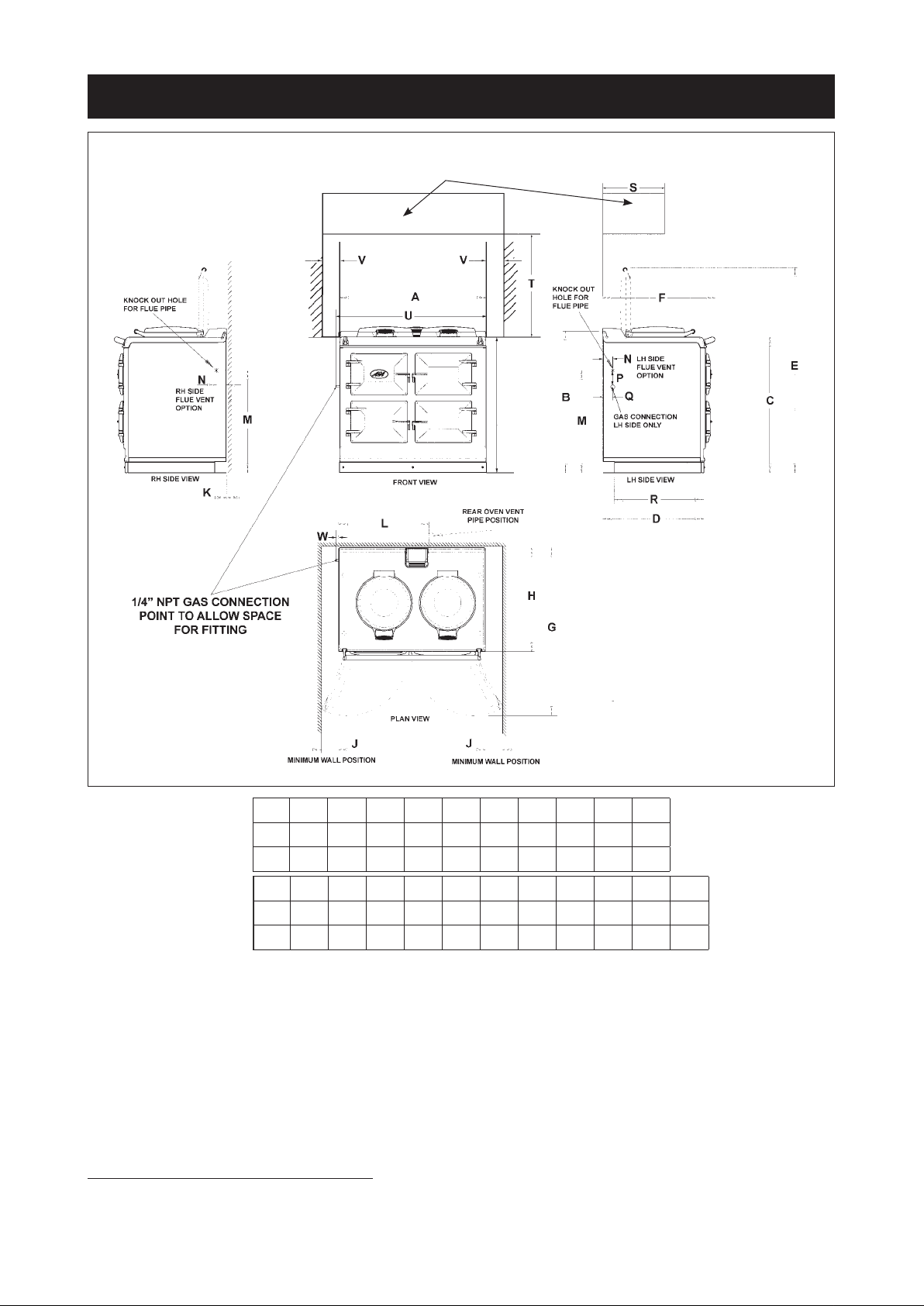
APPLIANCE DIMENSIONS - AGA DC3G
OVERHEAD
CUPBOARDS
Fig. 1 DESN 516847 A
A B C D E F G H J K
mm 987 951 913 680 1388 760 1145 698 116 10
38
7/8 37
inch
mm 565 689 43 118 55 634 330 760 996 75 9
22
inch
Range Dimensions
When surveying for a range installation the actual clearance required for the ‘body’ of the appliance should
be increased by 3/8” beyond the figures quoted above. This allows safe margin to take into account the
natural dimensional variations found in major castings. In particular the width across the appliance recess
could be critical.
APPLIANCE WEIGHT (Excludes Packaging)
Model: AGA Dual Control (DC3G) - 996lb (452kg)
GAS CONNECTION - AGA DC3G ONLY
1/4” NPT MALE AT LEFT REAR OF APPLIANCE
1/2 36 26 3/4 54
L M N P Q R S T U V W
1/4 27
1/8 1
3/4 4
5/8 29 7/8 45
5/8 2
1/8 25 13 30 39
1/8 27
1/2 4
9/163/8
3/16 3
3
/8
NOTE: GAS CONNECTION POINT PROTRUDES
5
Page 6
TECHNICAL DATA
Models AGA DC3G and DC5G
NATURAL GAS
MAXIMUM HEAT INPUT 6,800 Btu/hr
Thermostat Bypass 70
Main Burner Injector 112
Gas Supervision Injector 4212
Minimum Inlet Pressure 5” w.g.
Burner Pressure 4” w.g.
INSTALLATION
Range Base or Hearth
It is essential that the base or hearth on which the range stands should be level and be capable of supporting
the total weight of the range. The base of the built-in AGA plinth must be level and sit above the finished
height for service access.
Plinth
The front plinth cover is removable and must not be obstructed by flooring or tiles. If necessary the range
must be raised by the thickness of the tiles to ensure the plinth can be removed.
Rear Wall
Since this appliance runs continuously, please take note of these IMPORTANT instructions:
Combustible Walls
Houses constructed of combustible materials (such as all-timber or stud wall partitions and batoned
plasterboarded walls) require special wall heat protection features.
Non-combustible material behind a range must be of at least 1” (25mm) thick insulation board (Monolux or
equivalent), up to hotplate level.
SPECIAL NOTE: Ensure electric cabling or plastic services do not pass within or on the outside of the wall,
behind or directly above the range.
This type of material can age prematurely when exposed to continuous higher ambient temperature.
Alternatively the range can be spaced 1 1/2” (38mm) away from the wall to create an air gap.
The air gap must be left open and NOT blocked off across the top edge.
Side Clearances
1
A
/8” (3mm) gap is required each side between the range top plate and adjoining work surfaces that may be
fitted, this is to allow for the safe removal of the top plate should this be required at a later date.
Where ranges are to be fitted against a side wall a 4 9/16” (116mm) clearance is required on the right and left
hand side for oven door access.
If the AGA is to be installed in a brick recess, then the minimum clearance should be increased by at least
3
/8” (10mm), to allow for the walls not being square.
In addition a minimum clearance of 39 3/8” (1000mm) must be available at the front of the range to enable the
range to be serviced.
6
Page 7

Tiling
When the range is to stand in a recess or against a wall which is to be tiled, under no circumstances should
the tiles overlap the range top plate, access to remove the hotplate must be allowed for servicing at a later
date.
3
A gap of at least
/8” (10mm) must be observed from the rear of the top plate and the wall behind the range.
Overhead Cabinets
To eliminate the risk of burns or fires by reaching over hot surface units, cabinet storage space located
above the surface units should be avoided.
7
Page 8
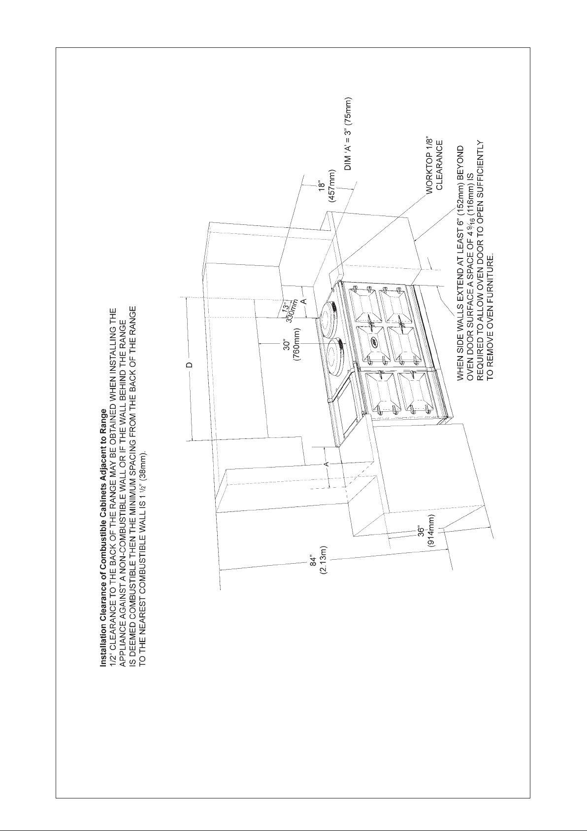
CABINETS MUST NOT EXCEED 13”
PROJECTED DEPTH ABOVE THE
RANGE.
DIM ‘D’ TO BE NOT LESS THAN THE
Fig. 2 DESN 516668
8
NOTE: ANY OVERHEAD FITTED
NORMAL WIDTH OF THE RANGE.
Page 9
Top Plate Adjustment - AGA DC3 (See Fig. 4)
In general, adjustment of the top plate is to be avoided. However minimum use of the top plate adjusters can
be used to improve the alignment of the top plate.
Fig. 3
DESN 516751
9
Page 10

CONNECTION TO THE POWER SUPPLY - AGA DC3G
Electric Shock Hazard
Rating Plate is located behind removable plinth, see Fig. 4A, Page 11
Electrical Grounding is required on this appliance.
DO NOT connect to the electrical supply until the appliance is permanently
grounded.
This appliance must be connected to a grounded metallic permanent supply or
a grounding connector should be connected to the grounding terminal or wire
lead on the appliance.
Failure to follow these instructions could result in death or serious injury.
This range must be supplied with a 240V, 60Hz power supply and connected to an individual, properly
grounded branch circuit protected by a circuit breaker. At 240V, it has a maximum load of 30 amps. Electric
hook-up must be done by a licensed electrician. This unit must be installed according to regional codes, or in
the absence of codes, the National Electrical Code.
l Product installation requires a separate (not shared) 240V/40 amp circuit protected by an
appropriate branch circuit supply.
l The service cord on your range is fitted with a standard four (4) prong type 14-50P plug
(matching receptacle 14-50R).
The method of connection to the mains electricity supply must facilitate complete electrical isolation of the
appliance.
The mains connection and isolation should not be positioned above the range and must be positioned within
the area defined in Fig. 4A, Page 11.
THIS RANGE MUST BE COMPLETELY ISOLATED FROM THE ELECTRICITY SUPPLY BEFORE
SERVICING. THE RANGE IS DESIGNED FOR THE VOLTAGE STATED ON THE RATING PLATE,
WHICH IS SITUATED BEHIND THE PLINTH COVER.
10
Page 11

MAINS CABLE ROUTING - AGA DC3G
MAINS CABLE FED FROM
CONTROL TRAY LEFT OR
RIGHT EXIT THROUGH
DUCTING DEPENDENT UPON
POSITION OF SUPPLY SOCKET
Fig. 4
RATING LABEL LOCATED
BEHIND PLINTH, PULL
TO REMOVE
THE MAINS SUPPLY CONNECTION AND ISOLATION POINT MUST BE WITHIN
THE ZONE SHOWN
DESN 516643
Fig. 4A DESN 516295
11
Page 12

FLUE SYSTEM
SEE FIGS. 5, 6, 7, 8 & 9
The flue system must be installed in accordance with the federal, state and local codes.
Only genuine AGA approved flue pipe is to be used.
Maximum permitted flue length run including bends is 13 ft.
Products of combustion discharge is by a fan powered flue pipe of 2” (50mm) diameter which can reach up
to 13’ (4 metres) in length through a maximum of 4 x 90° bend. Exits from the appliance can be from rear, LH
or RH sides. (See Figs. 6 and 7).
The flue pipe should protrude through the outside wall fixing plate by 1” (25mm) (See Fig. 5).
Terminal Position
The minimum acceptable spacings from the terminal to obstructions and ventilation openings are as shown
in Fig. 7.
Where the terminal is fitted within 23 5/8” (600mm) below plastic guttering an aluminium shield 39 3/8”
(1000mm)
long should be fitted to the underside and immediately beneath the guttering or eaves.
Where the terminal is fitted within 17 3/4” (450mm) below eaves or painted guttering an aluminium shield 29
1
/2 (750mm) long should be fitted to the underside and immediately beneath the guttering or eaves.
Terminal Protection
A terminal guard is supplied with the range and must be fitted, if flue termination is less than 78
metres) above ground level, or subject to damage.
When fitted, it must be positioned to provide a minimum of 2” (50mm) clearance from any part of the terminal
and be central over the terminal.
3
/4” (2
EXTERNAL
WALL
1”
(25mm)
COMBUSTIBLE
1 1/2”
(38mm)
WALL
VENT PIPE
5” (137mm)
Fig. 6 DESN 517038
NOTE: A 5” hole clearance is required through
combustible material, to allow 1 1/2” clearance
around flue pipe, (See Fig. 6).
Fig. 5 DESN 511196
12
Page 13

Minimum siting dimensions for flue terminals
Position Spacing
A Directly below an openable
window, air vent, or any other
ventilation opening
B Below gutter, drain/soil pipe 3
C Below eaves 7
D Below a balcony or car port roof 7
E From vertical drain pipes and soil
pipes
F From internal or external corners 11
G Above adjacent ground or bacony
level
H From surface facing the terminal 23
I Facing terminals 47
J From opening (door/window) in
car port into dwelling
K Vertical from a terminal 59
L Horizontally from a terminal 11
Minimum
inch/mm
11
7/8”/
7/8”/
5
7/8”/
11
1/4”/
1/4”/
47
3/4”/
”/
3/4”/
3/4”/
5/8”/
”/
1500
3/4”/
300
75
200
200
150
300
300
600
1200
1200
300
AROUND THE HOUSE
DESN 511052
UNDER THE CAR PORT, ETC.
Fig. 7
DESN 511053
13
Page 14

Fig. 8
DESN 516850
14
Page 15

11 3/4” (300mm) MIN.
31 1/2” (800mm) MAX.
11 3/4” (300mm) MIN.
31 1/2” (800mm) MAX.
157 1/2”
(4m) MAX.
/4”
3
11
(300mm)
MAX.
157 1/2”
(4m) MAX.
DOWNWARD RUNS UP TO 11 3/4”(300mm) BELOW THE APPLIANCE ARE ALLOWED, PROVIDED ONLY
ONE BEND IS USED.
DOWNWARD RUNS USING 2 BENDS ARE NOT ALLOWED.
MAXIMUM VERTICAL RISE = 59 1/16” (1500mm)
VERTICAL RISE MUST BE AT LEAST 11 3/4” (300mm) FROM PRODUCT BUT NO MORE THAN
31 1/2” (800mm) BEFORE VERTICAL.
Fig. 9
DESN 517112 A
15
Page 16

WIRING DIAGRAM - AGA DC3G
Fig. 10
16
Page 17

GAS SUPPLY - U.S. PIPE THREADS
NOTE: A MANUAL SHUT-OFF VALVE MUST BE INSTALLED IN AN ACCESSIBLE LOCATION IN THE
GAS PIPE EXTERNAL TO THE APPLIANCE FOR THE PURPOSE OF TURNING ON OR SHUTTING OF
GAS TO THE APPLIANCE.
ALL GAS CONTROLS MUST BE U.S. PIPE THREADS.
Maximum Heat Input 2 kW (6,800 Btu/h).
Gas Inlet Pipe: 1/4” NPT male at left rear of appliance.
The maximum gas inlet pressure at the range must not exceed 10 inches w.g. for Natural Gas. The minimum
gas inlet pressure at the appliance must be 5 inches w.g. Natural Gas to enable the correct manifold
pressure to be obtained.
The range and its individual shut-off valve must be disconnected from the gas supply piping system during
any pressure testing of that system at test pressures in excess of 1/2 psig (3.5 kPa). The range must be
isolated from the gas supply piping system by closing its i manual shut-off valve during any pressure testing
of the gas supply piping system at test pressure equal to or less than 1/2 psi (3.5 kPa).
On completion test the gas installation for soundness and purge. Leak testing of the range shall be
conducted according to the manufacturer’s instructions.
NOTE: Use soapy water solution on new gas connections to ensure there are no gas leaks.
On DC5 models, the gas inlet pipe and the vent pipe run behind the hotcupboard, (See Fig. 11)
VENT PIPE AND GAS INLET PIPE RUN
BEHIND THE HOTCUPBOARD
Fig. 11
DESN 517039
AIR SUPPLY
Kitchen or Internal Air Supply
The appliance can only be installed in a room which meets ventilation regulations in force but in any event the
room must have a permanent vent of minimum free air area 36cm
In the event of an extractor fan being fitted in the vicinity of the range, compensatory ventilation will be required
to satisfy the demands of the fan without influencing combustion efficiency and flue conditions.
17
2
(14in2).
Page 18

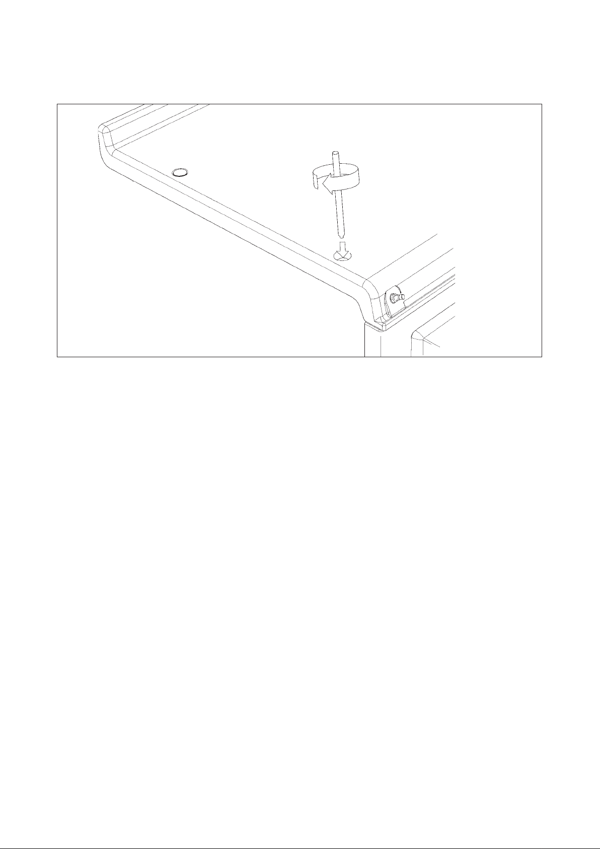
AGA DC3G P/F HANDRAIL CONNECTION
1. Fit the handrail bracket over the fixing stud located on the top plate. Lock into position by tightening the grub
screw nearest the appliance. (See Fig. 12).
Fig. 12
2. Next the handrail, endcaps and handrail require assembly.
Slide the handrail through the handrail brackets.
AGA DC3 HANDRAIL CONNECTION
DESN 516883
Fig. 13
DESN 516880
18
Page 19

3. Once the handrail assembly is located squarely, lock the handrail in position by winding in the grub
screws on the underside of each handrail bracket.
4. Once the handrails are locked in position, fit the handrail endcaps. The endcaps should be carefully
pushed into place until they sit flush with the outside face of each bracket (a light smear of lubricant such
as, hand or dish soap on the end cap ‘O’ rings may ease fitment.
5. Finally, fit the plinth facia to the magnets on the front of the plinth. Make sure that the plinth facia is
centrally located and does not overhang the range.
Commission the AGA Dual Control, as stated in the relevant Installation Instructions and carry out functional
test on each of the features of the AGA Dual Control.
19
Page 20

COMMISSIONING
Fig. 14 DESN 516966
Inlet Pressure Testing
1.
Turn off control knob (A) and turn off electrical supply to range.
2. Remove facia by pulling off hotplate control knob and removing four fixing screws.
Remove inlet pressure test nipple sealing screw (D) and fit rubber tube over the nipple.
3.
4. Turn on gas cock (C) and refit facia making sure the rubber pressure test tube is routed through the
hotplate control knob hole within the facia.
5. Attach tube to manometer.
6. Turn on electricity supply.
7. Follow paragraphs 1-4 of ‘LIG HTING PROCEDURE’ on page 21, and check inlet pressure, 8” w.g.
Burner Pressure Testing
1.
Turn off control knob (A) and turn off electrical supply to range.
2. Remove facia by pulling off hotplate control knob and removing four fixing screws.
3.
Remove inlet pressure test nipple sealing screw (E) and fit rubber tube over the nipple.
4. Turn on gas cock (C) and refit facia making sure the rubber pressure test tube is routed through the
hotplate control knob hole within the facia.
5. Fit manometer tube to test nipple (E).
6. Turn on electricity supply.
7. Follow paragraphs 1-4 of ‘LIGHTING PROCEDURE’, and check burner pressure 4” w.g.
NOTE: Burner pressure adjustment screw is located behind valve cover.
Check for leaks around pressure test nipple after refitting.
Leak testing of the appliance shall be conducted according to the manufacturers instructions.
(See ‘YEARLY SERVICE’)
20
Page 21

COMMISSIONING
CAUTION: BEFORE LIGHTING: ENSURE KNOB (A) IS IN THE OFF POSITION (SEE FIG. 27). ALSO
ENSURE GAS SUPPLY TO RANGE IS ON, AND THE GAS SERVICE COCK (C) IS IN THE ON POSITION
(SEE FIG. 31), AND THE ELECTRICAL SUPPLY TO THE AGA IS SWITCHED ON.
LIGHTING PROCEDURE - SEE FIGS 15 - 23
1. The main burner gas flow is set with the oven thermostat control knob (B). (See Fig. 14). First, ensure
both knobs are turned fully clockwise. Knob (A) to the OFF position and oven thermostat control knob (B)
to the minimum setting (thin end of the white band).
2. Turn oven gas control knob (A) slightly anti-clockwise towards the IGNITION position ( ) until reaching
stop, press down and hold for 5 seconds (gas flows only to the flame supervision burner). (See Fig. 16).
3. Continue pressing down knob (A) while turning further anti-clockwise to the ( ) position (this activates
the spark ignitor), continue to hold down for 10 seconds after flame supervision burner has been lit. (If it
does not light, steps 2 and 3 can be repeated). (See Fig. 17).
4. Upon lighting, release knob and turn further anti-clockwise to the ON position (large flame symbol) (See
Fig. 18). Pilot gas flows and mains gas flows according to the appliance setting (knob B).
5. Turn the oven thermostat control knob (B) slightly anti-clockwise into the white band (LOW FIRE position).
Leave in the low fire position for at least 60 minutes, (See Fig. 19).
NOTE: ‘LOW FIRE’ position is attained by turning knob (B) gradually into the white band, until a small flame
along the main burner is observed through viewing window (F). (See Fig. 14).
6. After at least 60 minutes rotate control knob (B) anti-clockwise to the mid-position of the green band for
normal running. (See Fig. 20).
NOTE: It will take up to 24 hours for all ovens to reach operating temperature, the oven heat indicator may
display green before this. Once the oven temperatures are at operating temperature it may be necessary
to make fine adjustment to the oven control knob to achieve the desired temperatures. It is not advisable to
make further changes to the control knob once the desired temperature is achieved.
When the range is lit from cold, moisture may form on the enamel which should be wiped off to prevent
staining.
IF THE FLAME HAS EXTINGUISHED FOR WHATEVER REASON, WAIT THREE MINUTES AND
REPEAT THE LIGHTING PROCEDURE.
YEARLY SERVICE
It is recommended that the range be serviced at regular intervals.
Arrange with the home owner that the range has been turned OFF the night before to ensure it is cold upon
arrival.
1.
Turn off power to the range.
2. Isolate the gas supply by turning off the gas shut off valve, See Fig. 14. This is accessed by removing the
control panel facia (4 screws).
3. Break the hexagon union nut and remove two burner fixing screws, See Fig. 14.
4.
Locate electric wires from gas valve and solenoid, disconnect inline connectors.
5. The burner assembly can now be withdrawn from the combustion chamber.
NOTE: Check there is sufficient length of thermostat capillary tube to allow the burner assembly to be rested
on a work surface without detaching the sensing end from the top of the roasting oven.
6. Lightly brush the perforated top of the gas burner and check that the burner venturi is free of lint and fluff.
NOTE: IT MAY BE NECESSARY TO DETACH THE FLAME SUPERVISION ASSEMBLY FROM THE BURNER
TO ENSURE IT IS FREE.
21
Page 22

Check the condition of the flame supervision thermocouple tip to ensure it is clean and free of carbon.
7.
Heavy heat oxidised tips should mean the removal of the thermmocouple and a new replacement.
Examine and brush the pilot light parts and examine the ignitor cable to ensure the PTFE insulation
remains intact and is firmly connected to the spark electrode. Clean any carbon away from the electrode.
8. Refit the gas burner assembly in reverse manner.
NOTE: USE SOAPY WATER SOLUTION TO ENSURE THERE ARE NO GAS LEAKS.
9. Inspect and clean vent fan blades, remove debris using a soft brush, access to this fan can be made by
removing the centre shroud (one screw fixing inside top outlet slot).
10. Turn on the gas and electric supply and follow the procedure for lighting the burner.
11. Ensure that the pilot and main burner flame are burning evenly, the thermocouple is enveloped by the
pilot flame.
12. Visually check the main burner and flame supervision flame for correct flame pattern. An established
main burner at high fire will be predominantly blue with yellow tippings on an even height flame strip and
be about 100mm (4in) high. Ensure all flame ports have cross-lit and that the flame supervision flame is
free from sooting.
13. The maximum depth of any cabinets installed above the top cooking surface of the range must not
exceed 330mm (13in).
NOTE: DO NOT ATTEMPT TO SERVICE THE RANGE YOURSELF, CONTACT YOUR LOCAL AGA
DISTRIBUTOR STATING THE MODEL AND SERIAL NUMBER OF THE APPLIANCE TOGETHER WITH
YOUR NAME AND ADDRESS.
Fig. 14 A MAIN BURNER DESN 516967
REPLACEMENT PARTS
In the event of a component failure which requires replacement, contact your local AGA distributor who will
advise and supply the necessary replacement.
INSTRUCTIONS
Hand these instructions to the user for retention, and instruct in the safe operation of the appliance.
22
Page 23

OFF POSITION
Fig. 15
IGNITION POSITION
Fig. 16
FLAME SUPERVISION
BURNER POSITION
Fig. 17
LOW FIRE
Fig. 19
MAIN BURNER
ON POSITION
Fig. 18
NORMAL RUNNING
Fig. 20
23
Page 24

CONTENT LIST (LOOSE ITEMS)
DESCRIPTION PART NO QTY TICK
BAKING OVEN CALIBRATION PLATE AE2M231432 1 ( )
OVEN GRID SHELF AE4M211863 3 ( )
SHELF - OVEN AG2M210636 1 ( )
GRILL RACK - LARGE AG4M210268 1 ( )
GRILL RACK - SMALL AG4M210269 1 ( )
WIRE BRUSH EACS23230 1 ( )
TOASTER EACS47380 1 ( )
MEAT TRAY - SMALL EMTY530217 1 ( )
MEAT TRAY - LARGE EMTY530218 1 ( )
AGA RECIPE BOOK (2 & 4 OVEN) EACS40640 1 ( )
PLINTH FACIA ASSY AE1M231475 1 ( )
PLATE - OUTLET BLANKING AG2M210568 4 ( )
HANDRAIL AE4M231411 1 ( )
HANDRAIL MOUNTING BRACKET AE4M212288 2 ( )
‘O’ RING (SMALL) AE4M212293 4 ( )
END CAP (HANDRAIL) AE4M212290 2 ( )
M5 x 12mm CONE POINT GRUB SCREW KGRB500674 2 ( )
SCREW M5
FLUE PIPE - HORIZONTAL AG4M210566 1 ( )
ALLEN KEY 2.5 mm AE4M280592 1 ( )
ALLEN KEY 3 mm AE4M280593 1 ( )
HOB ADJUSTER TOOL AE4M280388 1 ( )
FLUE PIPE ‘S’ BEND AG4M212518 1 ( )
COUPLING KIT AG4M211746 1 ( )
‘O’ RING KIT AG4M211747 1 ( )
BRACKET - FLUE PIPE AG4M210358 1 ( )
SCW M5 x 8mm PAN HD POZI Z/P KPAN52581 2 ( )
PACKED SEPARATELY
FLUE PIPE/TERMINAL GUARD AG1M212487 1 ( )
FLUE EXTENSION KIT AG1M212542 AS REQUIRED ( )
x 10mm SOCKET HD GRUB KGRB50509 2 ( )
24
Page 25

252627
Page 26

Page 27

Page 28

For further advice or information contact your
local AGA Ambassador
With AGA Marvel’s policy of continuous product
improvement, the Company reserves the right to
change specifications and make modifications to
the appliance described and illustrated at any time
Supplied by
AGA Marvel
1260 E. Van Deinse St.
Greenville, MI, 48838
Business (616) 754-5601
Fax (616) 754-9690
Toll Free Telephone 800-223-3900
www.agamarvel.com
28
 Loading...