

Page 1
Iconic design, exception quality
AG-9991 110912
Site Requirements
DESIGN MANUAL for AGA Products
Page 2

Design Guide
is guide was designed to provide a basic overview of site considerations that must be taken when purchasing AGA products. It is
not a substitute for the specic installation instructions that are delivered with the unit itself. Please refer to these instructions at the time
of installation.
All AGA products have been certied by the American Gas Association, the Canadian Gas Association and Underwriters
Laboratories to meet appropriate codes for use in North America. In addition, these products are approved for sale in the state of
Massachusetts.
e Information presented herein is based on the best data available and is believed to be correct. However, nothing stated herein
is to be taken as warranty expressed or implied, regarding the accuracy of the information or the use of our product(s). Specications
are subject to change without notice. Such revisions do not entitle the buyer to corresponding changes, improvements, additions,
replacements or compensation for previously purchased products.
Due to continuing product improvements, AGA Marvel reserves the right to amend specications without notice. Please contact
AGA Marvel for the most up to date information, as it applies to product being purchased, or download the latest Design Guide from
www.aga-ranges.com.
Note: e 2,3 and 4 Oven AGA MUST be installed by an authorized AGA installer. Failure to do so will void product
warranty. To locate your nearest installer, contact your dealer, visit our website www.aga-ranges.com or call 1-800-223-3900.
AGA is distributed in North America by AGA Marvel, 1260 East Van Deinse Street Greenville, MI 48838 Tel:800-223-3900
Due to continuing product improvements, AGA Marvel reserves the right to amend specifications without notice. Please contact AGA Marvel for the most up to date
information, as it applies to product being purchased, or download the latest Design Guide from www.aga-ranges.com.
2
Page 3
2, 3 and 4 Oven AGA Cooker
PLEASE READ BEFORE ORDERING
AGA cookers are made to order and built in your home by an authorized AGA tter. As each site is dierent, each AGA
conguration is dierent. erefore it is important to review the following site requirements prior to placing an order. Hearth
preparation, gas lines vent pipe options and electrical power needs must be assessed to determine the proper conguration. We strongly
recommend a home survey with the authorized tter who will be performing your installation. is will ensure the proper conguration
is ordered and materials needed will be available for installation. Ordering the wrong conguration could result in an installation delay.
To locate the authorized fitter nearest you, visit our website at www.aga-ranges.com or call Customer Care at 800-223-3900.
SITE PREPARATION
Weight:
Floor must be able to support the weight of the cooker. A location over or adjacent to a load-bearing wall is normally sucient. e
addition of a support joist from below may be needed. Your site surveyor will determine if this is necessary.
• 2 and 3 Oven 900 pounds
• 4 Oven 1300 pounds
PLINTH
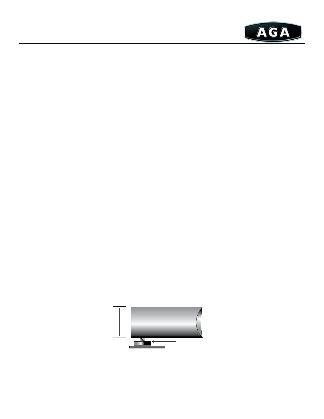
AGA cookers can be built on a plinth or hearth or both. A pre-fabricated Plinth can be ordered with your cooker. is is a steelconstructed frame which comes in three separate units to allow for custom conguration. It is adjustable and can raise the cooker 1½”.
e face of the hearth will accept certain adhesives and can be nished with wood, tile, etc.
NOTE:
If more height is required a hearth will need to be built in conjunction with the pre-fab Plinth or in lieu of the plinth.
• 2 or 3 Oven AGA - order A4117
• 4 Oven AGA - order A4117 and A4118
• Module attached to any cooker - order cooker Plinth# A4119
PLAN VIEW OF PRE-FABRICATED HEARTH
2”
(5 cm)
Leveling Leg & Pad
Side view of pre-fabricated plinth.
Due to continuing product improvements, AGA Marvel reserves the right to amend specifications without notice. Please contact AGA Marvel for the most up to date
information, as it applies to product being purchased, or download the latest Design Guide from www.aga-ranges.com.
3
Page 4
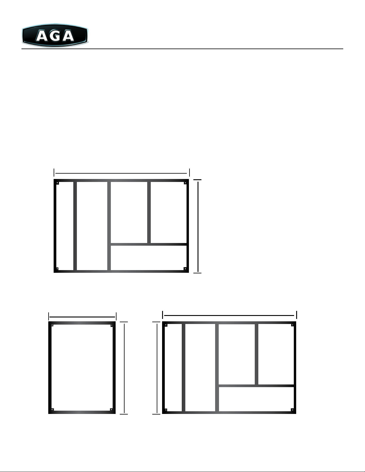
e nished overall dimensions for the Plinths are as follows.
Important: You must subtract Plinth measurements from oven measurements for thickness of finish material to be used on the front
and sides of the Plinth.
Important: Depth dimensions include the 1½”(3.81cm) space required for clearance to a combustible wall (In the case of a noncombustible wall (solid masonry) ¼”(0.75cm) clearance must be maintained). General counter opening is 38¾”(98.5cm) for a 2 or 3
Oven and 58⅞”(148.75cm) for a 4 Oven. Since the cooker’s top plate has a bevelled edge, enough room must be left to remove the top
for servicing, therefore opening requirements for various countertop edge finishes can vary and should be reviewed at your site survey to
determine the appropriate opening. When possible, we recommend the cooker be installed prior to cabinet and countertop installation.
2 and 3 Oven: 38¼”(97.25cm) wide x 26½”(67.31cm) deep without bar (29¾”(75.75cm) with towel bar) x height as required
5
/
38
”
8
(98.425cm)
Two Oven
Hearth
Model#:
A4117
26½” (67.31cm)
Front
4 Oven: 58½” wide x 26½” deep without bar (29¾” with towel bar) x height as required
5
/
38
”
19¼”
(48.9cm)
Hot Cupboard
Hearth
Model #:
A4118
Due to continuing product improvements, AGA Marvel reserves the right to amend specifications without notice. Please contact AGA Marvel for the most up to date
information, as it applies to product being purchased, or download the latest Design Guide from www.aga-ranges.com.
26½” (67.31cm)
26½” (67.31cm)
8
(98.425cm)
Two Oven
Hearth
Model#:
A4117
Front
4
Page 5
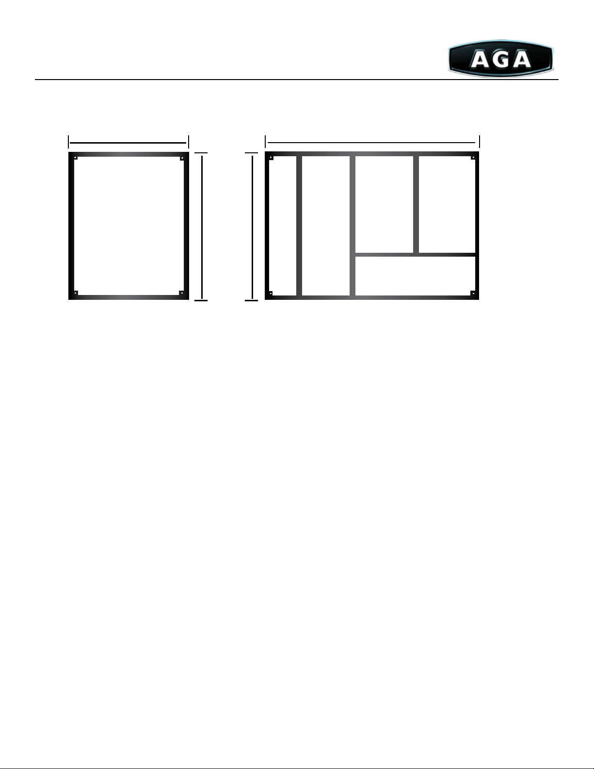
2 or 3 Oven with Companion: 61¾”(157cm) wide x 26½”(67.31cm) deep without bar (29¾”(75.75cm) with towel bar) x height
as required
5
/
38
231/8”
(58.75cm)
”
8
(98.425cm)
Companion
Hearth
Model #:
A4119
Front
26½” (67.31cm)
26½” (67.31cm)
Two Oven
Hearth
Model#:
A4117
Front
e AGA cooker cannot be moved once installed. At no time should joints be made inaccessible. A manual shut o valve is
supplied in the burner compartment. Most local codes require an external shut o valve upline from the cooker that is easily accessible. A
drip leg or dirt pocket should be used at the bottom of the supply line and should be accessible for cleaning or emptying.
Gas Plumbing
Burner capacity: Maximum input of 15,000 BTU’s per hour
Required gas pressure NG - 6-12 inches w.c. (1.74-2.98 kPa)
LPG - 11-14 inches w.c. (2.74-3.48 kPa)
Burner manifold pressure: NG - 4 inches w.c.
LPG - 10 inches w.c.
Gas pipe size: Gas connection is 3/8” N.P.T.
Due to continuing product improvements, AGA Marvel reserves the right to amend specifications without notice. Please contact AGA Marvel for the most up to date
information, as it applies to product being purchased, or download the latest Design Guide from www.aga-ranges.com.
5
Page 6

Electrical Requirements
e following is required for 2 Oven (A20-E) and 4 Oven (A40-E) electric models.
Electrical requirements: 220-240 Volt, 15 amp circuit
Energy usage: 2.5 kw/hour
Venting: Unlike gas models, these models do not require venting to the outside so they can
be sited anywhere in the kitchen.
Hood requirement: An overhead hood is not required, however if one is desired, it may be no more than
300 CFM.
Ventilation
Room Ventilation
Your kitchen needs to be designed for cross ventilation or adequate air circulation. When in use, the AGA generates far less heat
than conventional ranges or ovens, which often generate up to 50,000 BTU/hour. is issue will be addressed during your site survey and
should also be discussed with your kitchen designer or heating/cooling contractor.
ese are separate models and are not convertible from one to the other. Each vent type has specic installation requirements.
Please see the section of this book specic to your vent type for details. A certied AGA tter will determine which venting option best
suits your home. To nd out more about a site survey contact your local authorized AGA retailer.
Vent Type Location Models Available
Standard Vent rough roof 2,3 and 4 Oven Gas
Direct Vent Directly behind unit 2 and 4 Oven Gas*
Power Vent Anywhere 2 and 4 Oven Gas
Electric N/A 2 and 4 Oven Electric
*Note: Wall cannot be thicker than 22”
Due to continuing product improvements, AGA Marvel reserves the right to amend specifications without notice. Please contact AGA Marvel for the most up to date
information, as it applies to product being purchased, or download the latest Design Guide from www.aga-ranges.com.
6
Page 7
Direct Power
Standard Electric
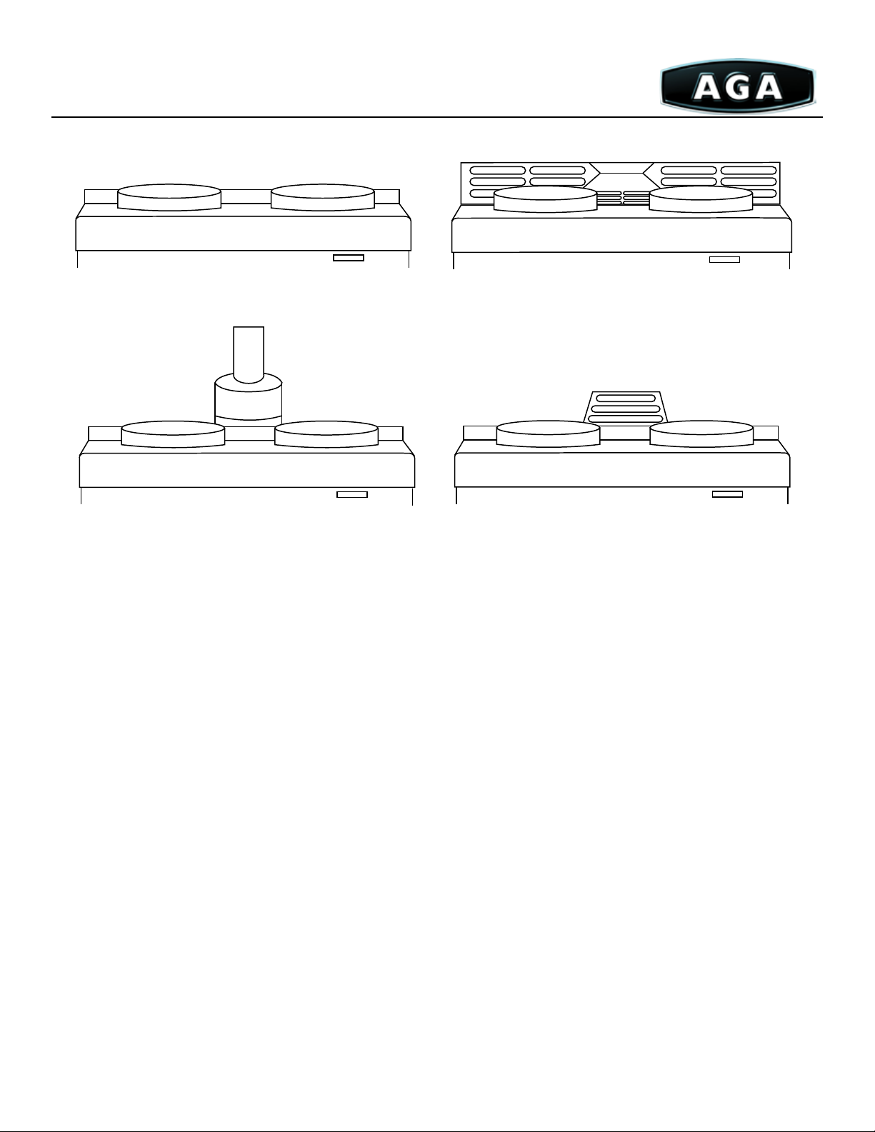
Standard Vent
(A20-SV, A30-SV, A40-SV Models)
Standard Vent is recommended when there is a choice among the three gas cooker options. It uses a vertical ue or chimney to send
exhaust gas through the roof. If a masonry chimney is already in place where the cooker will be located, it may serve as the ue if it meets
the requirements listed below. Otherwise, a 4”(10.25cm) (inside diameter), type B gas vent can be installed. Type B gas vent is a double
wall metal vent with an outside diameter of approximately 5(12.75cm) inches.
Black enameled pipe can make an aesthetic connection from the cooker to the ue or chimney. It is constructed of 4” diameter
black enamel steel and may be ordered with your cooker or through your installer.
is decorative ue pipe is designed for use in the open space above the Standard Vent cooker. When the pipe transitions through
a wall, cabinetry, or any other transition, a 5”(12.75cm) double wall Type B vent must be used. Refer to local building codes for details.
Consult with your tter to determine the quantity of pipe you require.
Due to continuing product improvements, AGA Marvel reserves the right to amend specifications without notice. Please contact AGA Marvel for the most up to date
information, as it applies to product being purchased, or download the latest Design Guide from www.aga-ranges.com.
7
Page 8
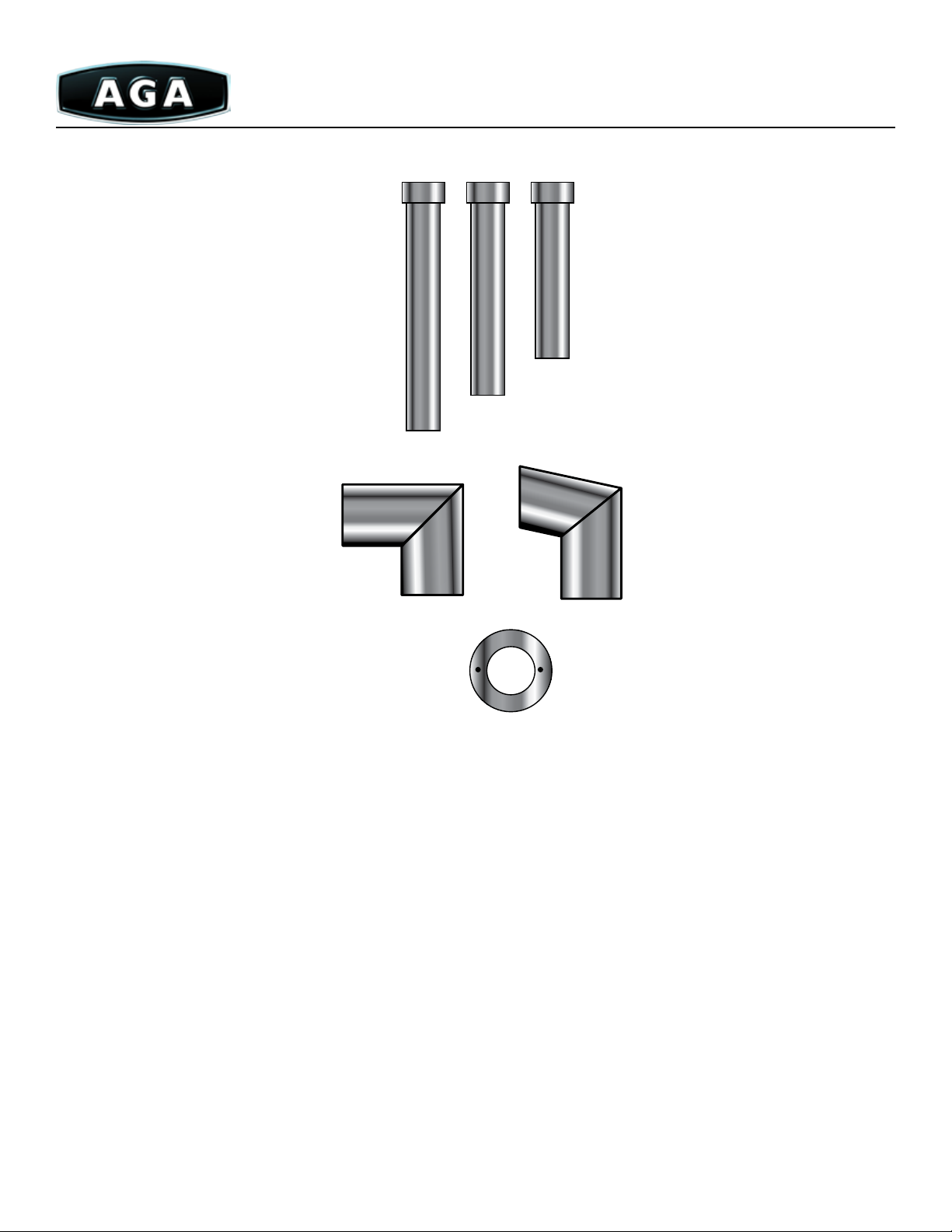
C
B
A
D
F
A - 4”D x 48”L Straight Length Model# - P1149
B - 4”D x 36”L Straight Length Model# - P1021
C - 4”D x 24”L Straight Length Model# - P1020
D - 4” 90 Elbow Model# - P1095 Steel w/ door
E - 4” 35° Elbow Model# - P1150 w/ door, Model# - P1141 w/o door
F - Sealing Collar - Enamel
E
Due to continuing product improvements, AGA Marvel reserves the right to amend specifications without notice. Please contact AGA Marvel for the most up to date
information, as it applies to product being purchased, or download the latest Design Guide from www.aga-ranges.com.
8
Page 9
Requirements
Masonry Chimneys
• Must be lined, clean and in good condition.
• Must have a ue size between 6”(15.25cm) and 8”(20.5cm) in
diameter. Larger ues will need a liner.
Type B Gas Vent
• Must be installed in accordance to the instructions provided
by the vent manufacturer.
• Requires a 1”(2.54) clearance to all combustible materials.
Eectively occupies a space of roughly 7”(18cm) in diameter
even though the vent is only about 5”(12.75cm) in diameter.
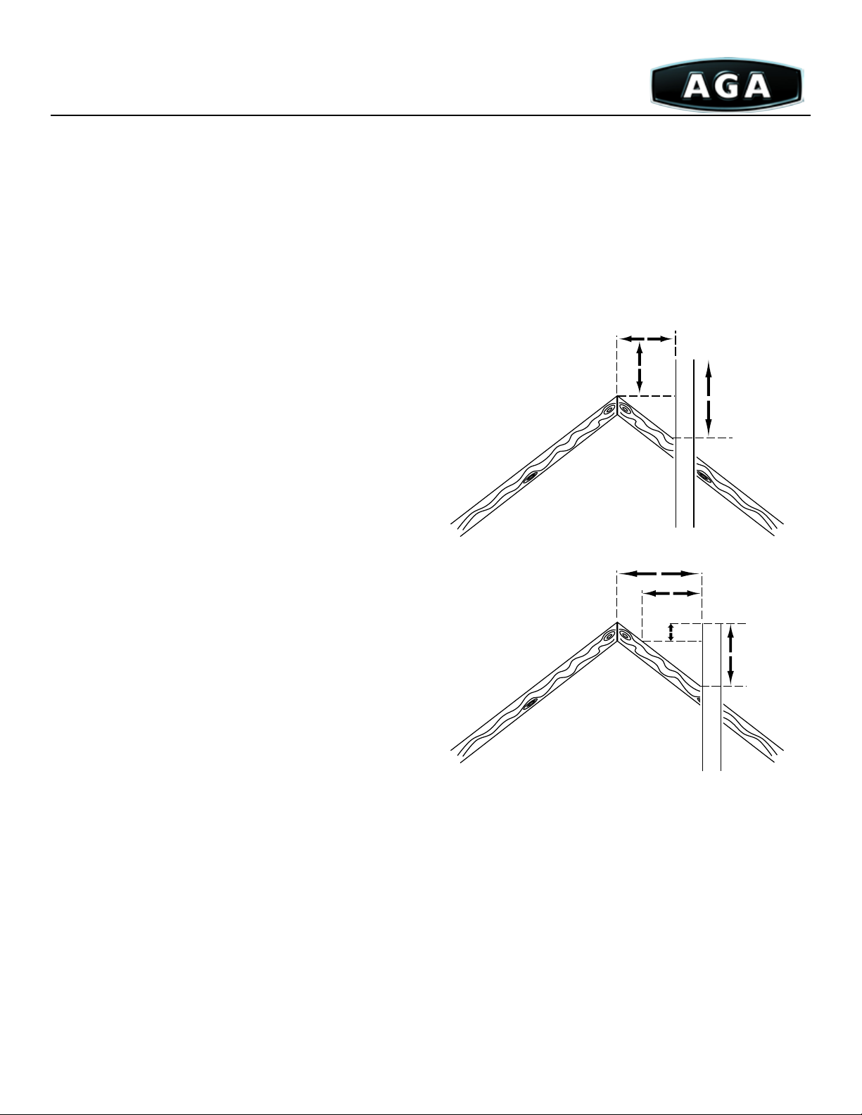
All Standard Vent Systems
• Must Extend at least 3’(91.5cm) above any roof penetration
and exceed to a point at least 2’(61cm) higher than anything
within a horizontal distance of 10’(305cm).
• Should be routed as vertically as possible avoiding 90° elbows
and horizontal runs where possible. e length of horizontal
vents (plus 5’(153cm) per 90° elbow plus 3’(91.5cm) per 45°
elbow) must not exceed the length of the vertical portion
of the system. Minimum slope is ¼”(0.75cm) per foot.
Minimum of 2’(61cm) rise is required before use of 90° elbow.
• Cannot be shared by appliances using dierent fuels. Be sure
to check if local gas venting codes apply. If so, nd out the
regulations. Fire stops are required by code where ue pipe
passes through oors or walls.
• e above information covers requirements of national codes
and should be sucient in most locations.
Ridge
Ridge
Less than 18’
(550cm)
2’ min
(61cm)
More than 18’
(550cm)
10’(310cm)
2’ min
(61cm)
Chimney
3’ (92cm)
Gas Vent
Chimney
3’ (92cm)
Gas Vent
Note: 90° bends should be avoided if possible.
Due to continuing product improvements, AGA Marvel reserves the right to amend specifications without notice. Please contact AGA Marvel for the most up to date
information, as it applies to product being purchased, or download the latest Design Guide from www.aga-ranges.com.
9
Page 10
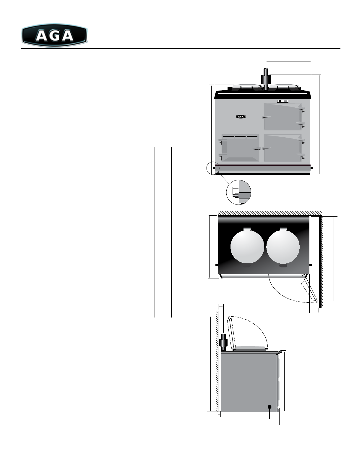
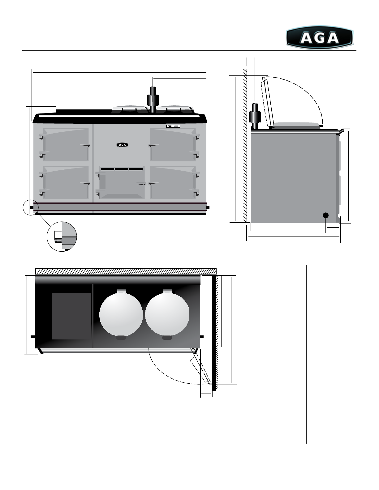
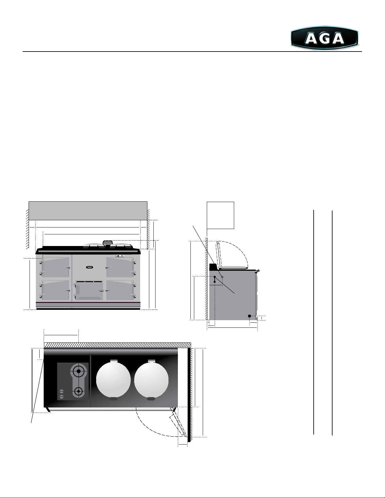
Model: 2 & 3 Oven
Standard Vent
Dimensions and clearances
Dimension A: Width of cooker
at widest point. Add ¼” (0.64cm) for
cabinet opening to give ⅛” (0.32 cm)
clearance on either side for assembly and
servicing of AGA (i.e., 58¾” (149.225cm)
cabinet opening for a four-oven and 39 ⅛”
(99.4cm) for a two-oven.)
Dimension D: Depth of the cooker,
includes the 1½” (3.81cm) rear clearance to
combustible walls (¼” (.635cm) to noncombustible surface).
Dimension G: Gas Connection can
be left hand, right hand or straight down
through the oor(not shown). Consult your
installer.
Dimension R: Clearance from righthand side. Applies only when a cabinet
or wall extends beyond (in front of) the
AGA. e oven doors must be able to open
beyond 90° because of their extra thick
insulation.
Dimension F: Height to top of
the ue collar. e vent pipe ts inside
and penetrates 1” (2.55cm). erefore,
the bottom of the vent pipe is 40½”
(102.87cm) above the base of the AGA.
Add the height of the hearth to get the
dimension above the oor.
Note: Any cabinets installed over an
AGA must be at least 30” (76.2cm) above
the cook top and may not project more
than 13” (33.25cm) from the wall.
A
B
C
D
E
F
G
H
J
K
L
M
N
P
R
S
Inches
38 ⅞
35
33½
7
28
/
18 ⅜
40½
1½
51¾
29¾
5
44
/16
4 ⅜
¾
1½
27½
6
2
A
B
E
F
cm
98.7
88.9
85.1
73.3
8
G
Front View
M
G
46.7
102.8
Combustable surface
3.8
131.4
75.6
112 .5
11.1
J
P
K
1.9
3.81
70
15. 2
5.1
L
Top View
Position when
lids raised
Oven door in
open position
R
Min. side wall
position
H
Combustible
3/8” A.P.T. Gas Conn.
L.H. or R.H. Side
or straight through
N
Due to continuing product improvements, AGA Marvel reserves the right to amend specifications without notice. Please contact AGA Marvel for the most up to date
information, as it applies to product being purchased, or download the latest Design Guide from www.aga-ranges.com.
floor.
D
Side View
C
S
10
Page 11
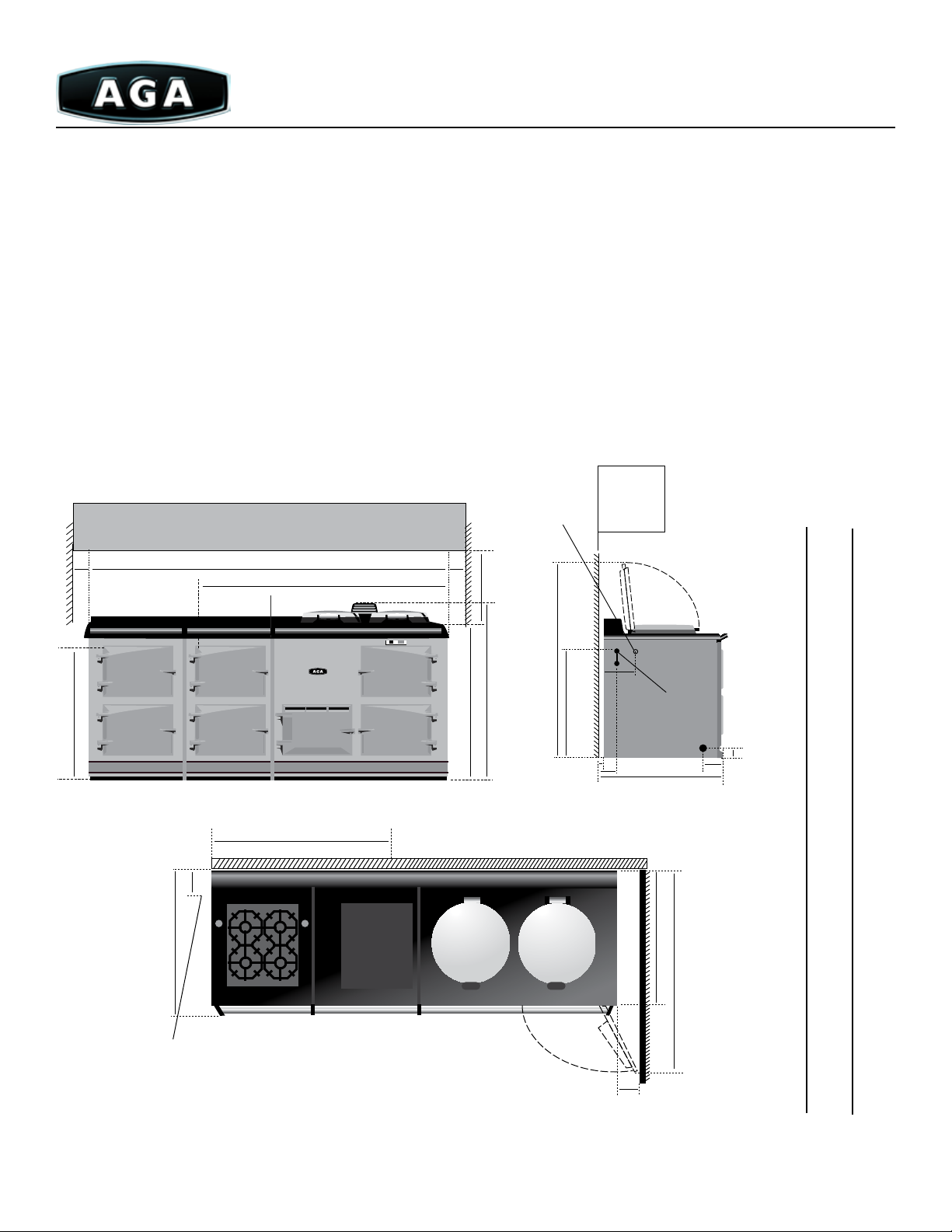
Model: 4 Oven Standard Vent
A
L
E
Position when
lids raised
H
B
F
Combustible
C
G
Front View
M
Combustable surface
J
G
3/8” A.P.T. Gas Conn.
L.H. or R.H. Side
or straight through
floor.
N
S
D
Side View
Inches
cm
58½
35
33½
7
28
18 ⅜
40½
1½
149
88.9
85.1
73.3
/8
46.7
102.8
3.8
A
B
C
D
P
E
F
K
G
52⅜
29¾
44
4 ⅜
¾
1½
27½
6
2
133
75.6
5
112 .5
/16
11.1
1.9
3.81
70
15. 2
5.1
H
J
Top View
Oven door in
open position
K
L
R
Min. side wall
position
M
N
P
Note: Please allow ¼” to non-combustible surface for servicing.
R
S
Due to continuing product improvements, AGA Marvel reserves the right to amend specifications without notice. Please contact AGA Marvel for the most up to date
information, as it applies to product being purchased, or download the latest Design Guide from www.aga-ranges.com.
11
Page 12
Direct Vent
(A20-DV, A40-DV Models)
Direct Vent models discharge directly out the back of the cooker and straight through and exterior wall. e entire combustion
system, including the combustion air intake, is sealed to the outside.
Direct Vent is recommended when the installation of a Standard Vent isn’t possible or in a super-insulated home where the make-
up for combustion may not be adequate or practical due to airtight construction.
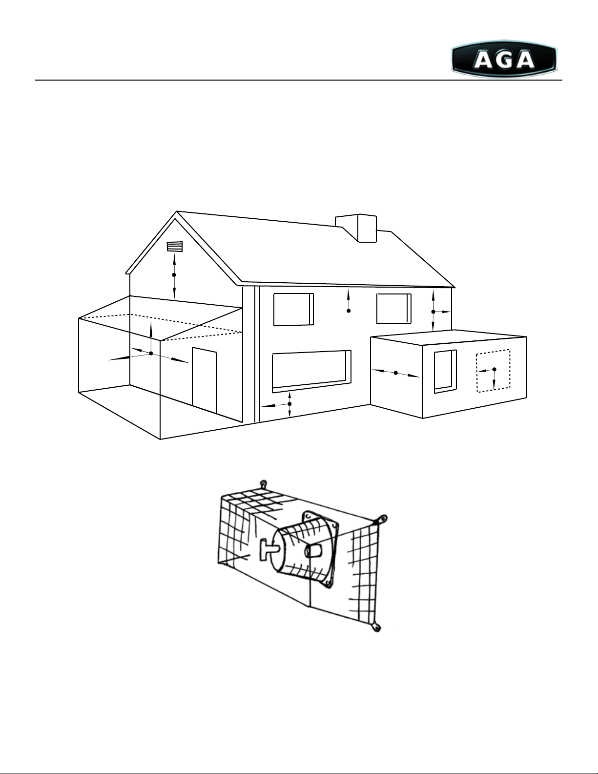
Direct Vent Requirements
• Must be located on an exterior wall no thick than 22”(56cm). e vent pipe going out the back must go directly through the
wall without any bends.
• Must be located so that the termination of the vent is at least 9”(23cm) from any opening into the building.
• Must be located so that the termination of the vent is at least 2’(61cm) below any projection such as eaves or a balcony.
• Must be located so that the termination of the vent is at least 2’(61cm) from any building inside or outside corner and at least
10’(305cm) from any nearby buildings.
Terminal Position Minimal Distance
Natural Draft
A Directly below an operable window or other opening (i.e. air, brick) 12”(31cm)
B Below gutters, soil or drain pipes 12”(31cm)
C Below eaves 12”(31cm)
D Below balconies or a car port roof 24”(61cm)
E From vertical drain pipes and soil pipes 3”(8cm)
F From internal and external corners 24”(61cm)
G Above ground, roof or balcony level 12”(31cm)
H From a surface facing a terminal 24”(61cm)
I From a terminal facing a terminal 24”(61cm)
J From an opening in the carport (i.e. door, window) into dwelling 48”(122cm)
K Vertically from a terminal on the same wall 60”(153cm)
L Horizontally from a terminal on the same wall 12”(31cm)
See Figure 1 on next page.
Due to continuing product improvements, AGA Marvel reserves the right to amend specifications without notice. Please contact AGA Marvel for the most up to date
information, as it applies to product being purchased, or download the latest Design Guide from www.aga-ranges.com.
12
Page 13
Please use dimensions I, O & Q to ensure there is no plumbing, wiring or framing in the wall where the tube kit must enter.
See previous Page for measurements.
A
C
B
SC
F
D
C
F
I
H
J
F
F
L
K
K
L
A
G
E
Figure 1
Due to continuing product improvements, AGA Marvel reserves the right to amend specifications without notice. Please contact AGA Marvel for the most up to date
information, as it applies to product being purchased, or download the latest Design Guide from www.aga-ranges.com.
13
Page 14

Model: 2 Oven
Direct Vent
Notes on Dimensions and
Clearances
Dimension A: Width of cooker
at widest point. Add ¼”(.75cm) for
cabinet opening to give ⅛”(.5cm)
clearance on either side for assembly and
servicing of AGA (i.e., 58¾”(149.25cm)
cabinet opening for a four-oven and 39
⅛”(99.5cm) for a two-oven.)
Dimension D: Depth of the
cooker, includes the 1½”(3.81cm) rear
wall clearance to combustible walls
(¼”(.625cm) to non-combustible
surface).
Dimension G: Gas Connection
can be left hand, right hand or straight
down through the oor(not shown).
Consult your installer.
Dimension R: Clearance from
right-hand side. Applies only when a
cabinet or wall extends beyond (in front
of) the AGA. e oven doors must be
able to open beyond 90° because of their
extra thick insulation.
Dimension I: Distance above the
hearth to the center line of both direct
tubes. Consult installer prior to drilling
hole as venting tube must be at an angle
of 1.5°.
Optional Gas Connection/
Dimension G, S, M: Optional throughtthe-oor gas connection requires a
2”(5.25cm) diameter hole in the hearth
and oor centered for the Mark III
burner 28½”(72.5cm) from the right, set
1¾”(4.5cm) from the front.
Note: Any cabinets installed over an
AGA must be at least 30”(76.2cm) above
the cook top and may not project more
than 13”(33.25cm) from the wall.
A
B
C
D
E
F
G
H
I
J
K
L
M
N
O
P
Q
R
S
Inches
38 ⅞
35
33½
7
28
/
18 ⅜
40½
1½
51¾
29¾
29¾
5
44
/16
4 ⅜
¾
1½
12 ⅞
26¾
16 ⅜
6
2
Combustable surface
O
Q
cm
J
98.7
88.9
85.1
72.3
8
46.7
102.8
3.8
131.4
76
75.6
112 .5
11.1
1.9
3.81
32.8
67. 9
41.6
15. 2
5.1
H
Top View
Surface
Position when
lids raised
Oven door in
open position
Min. side wall
position
P
K
R
C
I
Combustible
3/8” A.P.T. Gas Conn.
L.H. or R.H. Side
or directly through
floor
N
D
Side View
S
Due to continuing product improvements, AGA Marvel reserves the right to amend specifications without notice. Please contact AGA Marvel for the most up to date
information, as it applies to product being purchased, or download the latest Design Guide from www.aga-ranges.com.
14
Page 15

4 Oven - Direct Vent
Position when
lids raised
H
Surface
Inches
cm
58½
35
33½
7
28
18 ⅜
40½
1½
52⅜
29¾
29¾
5
44
4 ⅜
¾
1½
12 ⅞
27½
16 ⅜
/
/16
149
88.9
85.1
68.5
8
46.7
102.8
3.8
133
76
75.6
112 .5
11.1
1.9
3.81
32.8
70
41.6
A
B
C
D
C
I
Combustible
3/8” A.P.T. Gas Conn.
L.H. or R.H. Side
or directly through
floor
N
D
Side View
Combustable surface
S
O
Q
E
F
G
H
I
J
K
L
M
N
O
P
Q
P
R
15. 2
6
J
S
5.1
2
K
Top View
Due to continuing product improvements, AGA Marvel reserves the right to amend specifications without notice. Please contact AGA Marvel for the most up to date
information, as it applies to product being purchased, or download the latest Design Guide from www.aga-ranges.com.
Oven door in
open position
R
Min. side wall
position
15
Page 16

Power Vent
(A20-PV, A40-PV Models)
e Power Vent discharges products of combustion by a fan-powered vent pipe 2” (6cm) in diameter, which can reach up to
29’(884cm) with one 90° bend. See the table below for maximum lengths of vent pipe and allowable number of elbows. Downward runs
up to 12”(30.5cm) below the appliance are allowed, provided only one downward bend is used. See the diagram on page 21.
Exits from the appliance can be from the left hand or right hand sides, the rear, or throughout the bottom (see Figure 2). e vent
pipe must terminate horizontally and protrude through the outside wall xing plate by 1”(2.54cm)(see Figure 1). A ¼”(.75cm) clearance
to combustibles is required for the rst four feet of vent pipe.
Maximum Vent Lengths and Allowable Elbows
Maximum Length of Run Maximum Elbows (90°)
29’(8.85m) 1
27.6’(8.5m) 2
25.6’(7.9m) 3
23.6’(7.2m) 4
21.6’(6.6m) 5
19.7’(6.1m) 6
Terminal Position
• e cooker must be installed so that the vent terminal is exposed to the external air and terminal clearance complies with: e
National Fuel Gas Codes ANSI Z223 1 latest edition Section 7.7 (U.S.) CAN/CGA-B149 installation code. (Canada)
• Termination should be on a clear expanse of wall, the terminal being no less than 14”(35.75cm) away from a corner, recess or
projection.
• A hole must be cut through an outside wall with the hole falling 1.5° from inside to outside face of wall.
• Openings in the wall behind or on the oor below the appliance must be sealed using the closure plate.
DO NOT install the terminal:
• Within 12”(30.5cm) measured vertically, from the bottom of an operable window, air vent or any other ventilating opening.
• Within 12”(30.5cm) above adjacent ground level.
• Within 24”(61cm) of any surface facing the terminal.
• Within 14”(35.75cm) or 12”(30.5cm)(Canada) below eaves or balcony.
See diagram on page 20
e terminal must be protected by an installed terminal protective guard to prevent unauthorized contact with the hot terminal
surfaces (See Figure 1).
Due to continuing product improvements, AGA Marvel reserves the right to amend specifications without notice. Please contact AGA Marvel for the most up to date
information, as it applies to product being purchased, or download the latest Design Guide from www.aga-ranges.com.
16
Page 17
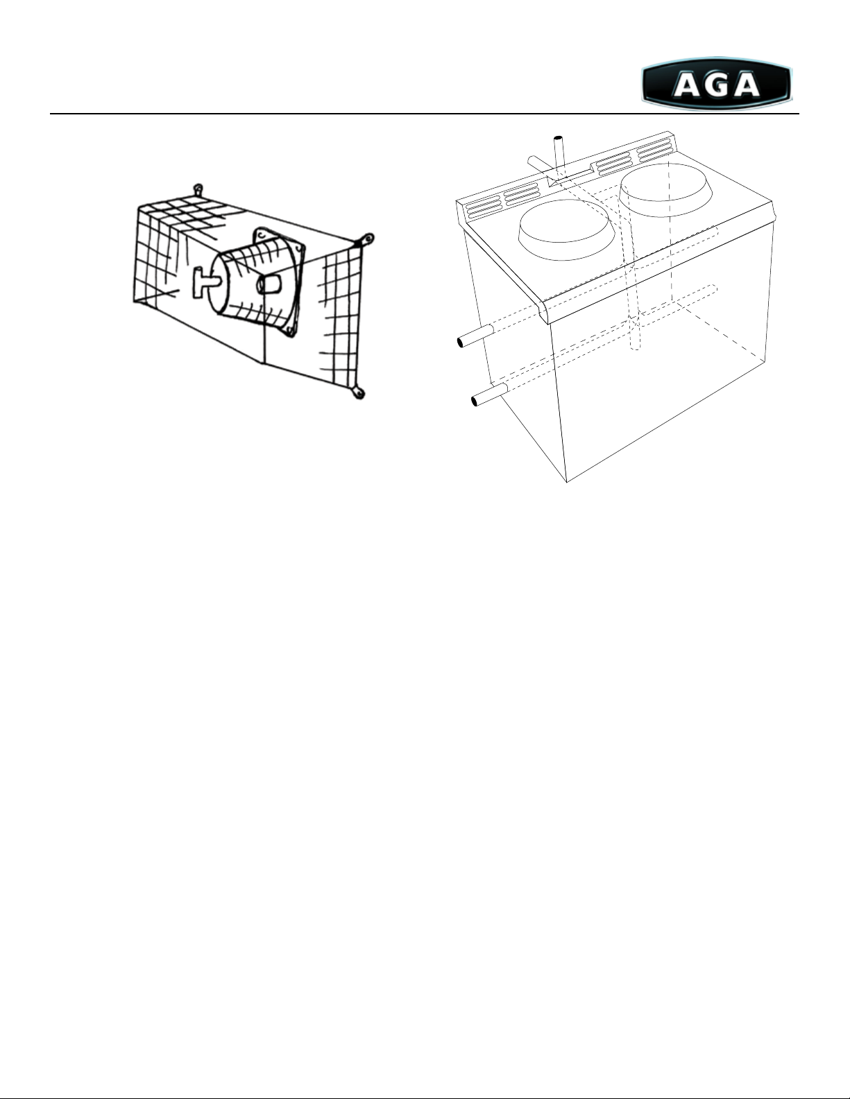
Fig. 1
Fi g. 2
Electrical
110/120V 60hz 10AMP exible cord and plug parallel type is supplied with the cooker. When installed, the appliance must be
electrically grounded in accordance with local codes, or, in absence of local codes, with the National Electrical Codes, ANSI/NFPA 70.
An electrical receptacle must be provided no more than 4’(122cm) of the left-hand side of the appliance and easily accessible for the user
to disconnect. Do not position the receptacle above or behind the appliance.
Warning!
is appliance is equipped with a three-prong grounding plug for protection AGAinst shock hazard and should be directly
plugged into a proper receptacle. DO NOT CUT OR REMOVE THE GROUNDING PRONG FROM THE PLUG.
Internal Air Supply
e appliance can only be installed in a room that meets ventilation regulations and has a permanent vent of minimum free air
area of 5.5sq”(35.5cm²). If an extractor fan is near the cooker, make-up air will be required to satisfy the demands of the fan without
inuencing combustion eciency or ue conditions.
Due to continuing product improvements, AGA Marvel reserves the right to amend specifications without notice. Please contact AGA Marvel for the most up to date
information, as it applies to product being purchased, or download the latest Design Guide from www.aga-ranges.com.
17
Page 18
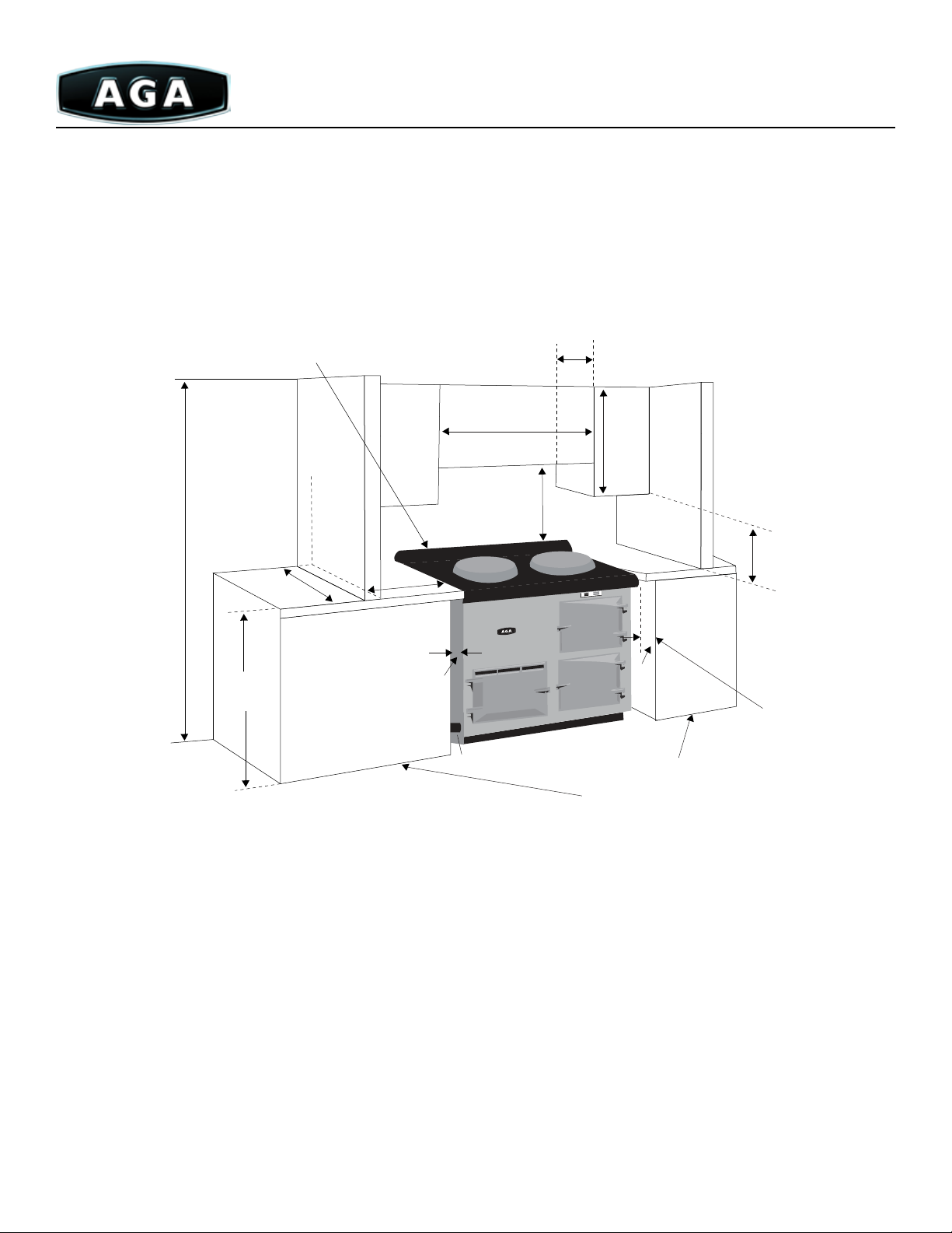
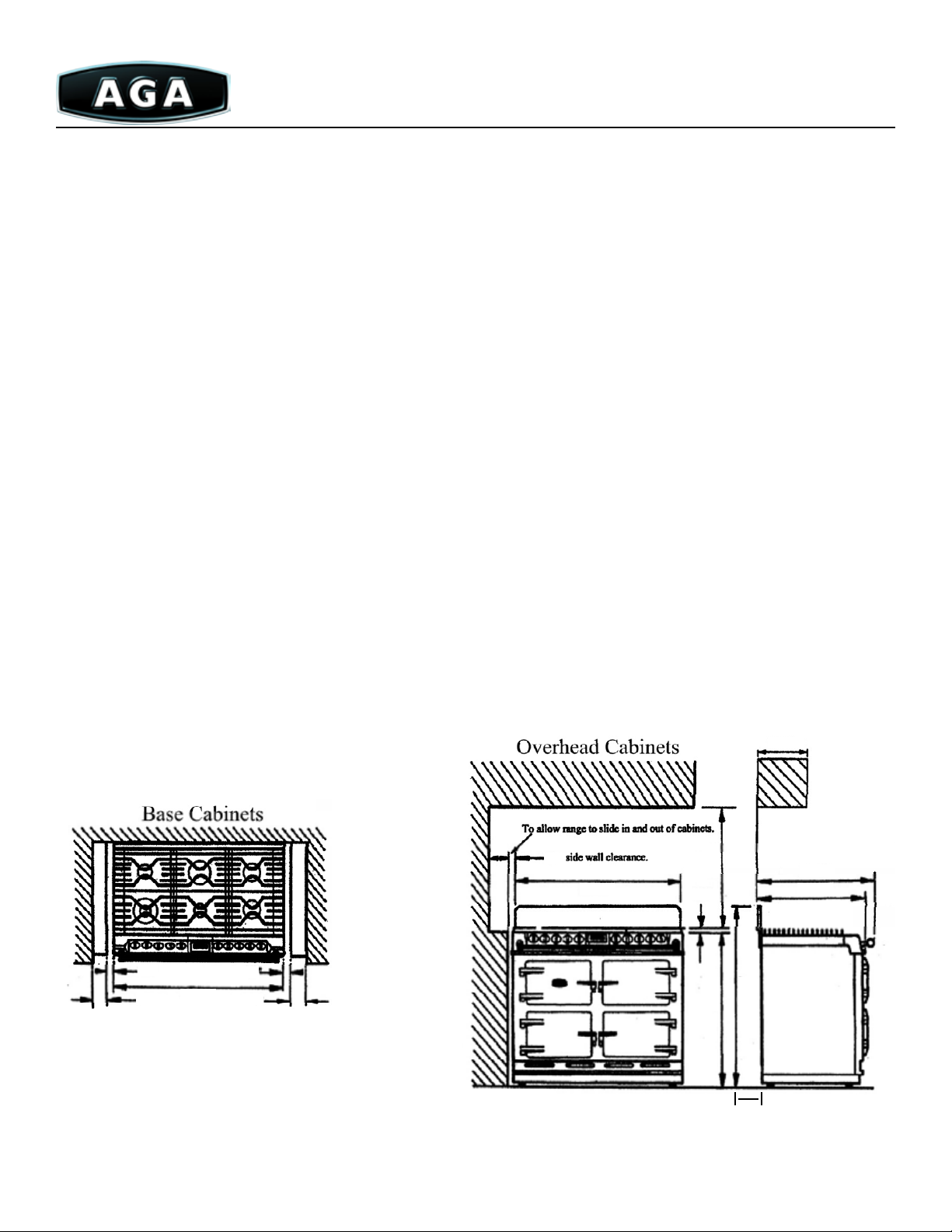
Installation Clearances of Combustible Cabinets
For right hand gas entry dimensions E & F are reversed.
Any overhead tted cabinets must not exceed 13”(33.25cm) projected depth above range dimension “D” to be not less than the
normal width of the appliance.
1½” clearance at back of cooker
to combustible surface.
(¼” to non-combustible surface)
13”
(33cm)
84”
(213cm)
(89cm)
36”
(91.4cm)
35”
Min 24”
(61cm)
clearance
Zero
E
LH Gas Entry
D
30”
(76cm)
30”
(76cm)
18”
(46cm)
F
Zero
clearance
Side walls extend
at least 6” (15cm)
beyond oven door
surface
Due to continuing product improvements, AGA Marvel reserves the right to amend specifications without notice. Please contact AGA Marvel for the most up to date
information, as it applies to product being purchased, or download the latest Design Guide from www.aga-ranges.com.
18
Page 19

Power Vent Options & Limitations
A
C
SC
B
F
D
C
F
I
H
J
F
F
L
K
K
L
A
G
E
Terminal Positions Min Distance
Natural Draft
A Directly below an operable window or other opening (air brick) 12” (31cm)
B Below gutters, sil pipes or drain pipes 12” (31cm)
C Below eaves 12” (31cm)
D Below balconies or car port roof 21” (54cm)
E From vertical drain pipes and soil pipes 3” (8cm)
F From internal and external corners 24” (61cm)
G Above ground, roof or balcony level 12” (31cm)
H From a surface facing a terminal 24” (61cm)
I From a terminal facing a terminal 24” (61cm)
J From an opening in the car port (door window) into dwelling 48” (122 cm)
K Vertically from a terminal on the same wall 60” (153cm)
L Horizontally from a terminal on the same wall 12” (31cm)
Due to continuing product improvements, AGA Marvel reserves the right to amend specifications without notice. Please contact AGA Marvel for the most up to date
information, as it applies to product being purchased, or download the latest Design Guide from www.aga-ranges.com.
19
Page 20
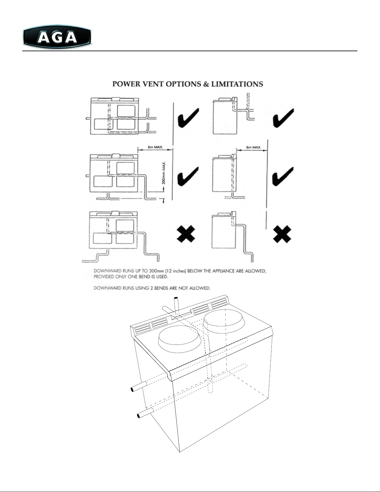
Downward runs up to 12” (31cm) below the appliance are allowed, provided only one bend is used.
Downward runs using 2 bends are not allowed.
Fi g. 2
Due to continuing product improvements, AGA Marvel reserves the right to amend specifications without notice. Please contact AGA Marvel for the most up to date
information, as it applies to product being purchased, or download the latest Design Guide from www.aga-ranges.com.
20
Page 21
Gas Hob Option for 4 Oven AGA
e Gas Hob option (Part number: GHO) replaces the Standard Warming Plate on the 4 Oven AGA with a two-burner cooktop.
is option MUST be specied at the time of purchase. It can not be retrot into an existing appliance.
Gas Hob option comes as a separate item and must be installed by a tter.
Gas Requirements
IMPORTANT: A manual shuto is required upline from the appliance. Do not t valve behind the appliance.
Electrical Requirements
110/120V 60hz exible cord and parallel type A 110v receptacle must be provided within six feet (183cm) of the left-hand side of
the unit.
Important: Do not position receptacle above or behind the appliance.
Overhead
Cupboard
D D
A
N
Overhead
Side entry
electrical connection
Q
(burner unit)
Cupboard
Position when
lids raised
Inches
58½
A
33½
B
7
28
C
D
E
3
52
/
8
3
/8
cm
148 .7
85.1
73.2
8
133
29¾
44¼
4½
9
14
27½
8¼
38
1½
52¾
11
32
13
28
2
1 ⅝
9
1
/
16
75.6
112 .5
11.6
37
/
16
70
21
96.7
3.81
134
83
/16
33
71.1
5.1
4.1
3.9
O
K
F
Side entry
electrical
connection
L
B
Power
Flue
Only
E
K
Combustible Surface
U
Gas knockout
F
G
H
I
Front View
M
R
I
Rear Entry
Electrical Connection
Combustable surface
3/8” A.P.T. Gas Conn.
L.H. or R.H. Side
or directly through
floor
C
Side View
S
T
J
K
L
M
N
J
O
P
G
Q
R
Top View
Oven door in
open position
H
Min. side wall
position
S
T
Due to continuing product improvements, AGA Marvel reserves the right to amend specifications without notice. Please contact AGA Marvel for the most up to date
information, as it applies to product being purchased, or download the latest Design Guide from www.aga-ranges.com.
21
Page 22
4 Oven AGA with Module
e Gas Hob option (Part number: GHO) replaces the Standard Warming Plate on the 4 Oven AGA with a two-burner cooktop.
is option MUST be specied at the time of purchase. It can not be retrot into an existing appliance.
Gas Hob option comes as a separate item and must be installed by a tter.
Gas Requirements
IMPORTANT: A manual shuto is required upline from the appliance. Do not t valve behind the appliance.
Electrical Requirements
110/120V 60hz exible cord and parallel type A 110v receptacle must be provided within six feet (183cm) of the left-hand side of
the unit.
Important: Do not position receptacle above or behind the appliance.
Overhead
Cupboard
A
B
Position when
lids raised
C
D
E
K
F
Combustible Surface
U
M
R
Gas knockout
3/8” A.P.T. Gas Conn.
L.H. or R.H. Side
or directly through
floor
C
Side View
G
H
S
T
I
J
Overhead
Cupboard
D D
O
A
N
Front View
Q
L
B
Power
Flue
Only
Side entry
electrical connection
(burner unit)
E
Inches
19
82
/
33½
7
27
/
8
3
51¾
29¾
44¼
4½
3
96
/
16
27¾
cm
209.7
32
85.1
73.2
75
131.4
75.6
112 .5
11.6
97
67. 9
8¼
38
1½
52¾
32
13
28
2
1 ⅝
9
1
/
27½
21
96.7
3.81
134
11
83
/16
33
71.1
5.1
4.1
3.9
16
69.8
K
F
Side entry
electrical
connection
I
Rear Entry
Electrical Connection
Top View
Combustable surface
Oven door in
open position
H
Min. side wall
position
K
L
M
N
J
O
P
G
Q
R
S
T
U
Due to continuing product improvements, AGA Marvel reserves the right to amend specifications without notice. Please contact AGA Marvel for the most up to date
information, as it applies to product being purchased, or download the latest Design Guide from www.aga-ranges.com.
22
Page 23

6-4 Series
(6:4 FFD)
Planning Information
e following specications provide overall dimensions, nished rough opening dimensions and gas/electrical requirements for
the AGA 6-4 Series dual fuel model. Please follow these guidelines when planning your installation to avoid damage to your range
and/or surrounding cabinetry. Refer to the installation guide included with your range for specic installation instructions.
Please be sure to consult a qualied electrician and ensure the installation conforms to all national and local electrical codes and
gas regulations.
Electrical Requirements
e electrical connection is located at the top right-hand side of the appliance behind the side panel. e right side panel of the
appliance must be removed in order to make the electrical connections. (See g. 2)
is appliance requires a dedicated 240 volt, 60hz, 30 amp four-wire, electrical supply. It can be tted with a UL-approved 30
amp range cord that matches a four-wire receptacle type 14-30R. An electrical socket type 14-30R must be provided no more
than 4 feet (122cm) from the left hand rear side of the range and accessible for disconnection.
Important: Do not position the socket above or behind the range.
Important: Electrical grounding is required on this appliance.
Warning: is appliance must be completely isolated from the electrical supply prior to servicing.
Cabinets
Rear Wall
(Combustable surface)
Gas supply exits the wall within
The shaded area.
Supply pipe must not project
more than 1¾”(4.5cm) from wall.
”
8
/
7
7
(20cm)
14½”(37cm)
”(66cm)
8
/
5
25
(10cm)
Aga 6-4 Rear View
Oven vents
Electrical cable connection
Electrical connections are
made behind side panel
½”(2cm) Female N.P.T.
gas connection
4”
Fi g. 1
4½”
(12cm)
21½”(55cm)
Fi g. 2
Due to continuing product improvements, AGA Marvel reserves the right to amend specifications without notice. Please contact AGA Marvel for the most up to date
information, as it applies to product being purchased, or download the latest Design Guide from www.aga-ranges.com.
23
Page 24
Gas Requirements
e gas feed is located on the center left hand rear of the unit. e appliance is supplied with a ½”(1.5cm) female NPT tting. (See
Fig. 2 on page 23)
e maximum gas inlet pressure at the appliance must not exceed 10”w.c. for natural gas and 14”w.c. for LPG.
e minimum gas inlet pressure at the appliance must not be less than 5”w.c. for natural gas and 11”w.c. for LPG.
e regulator is preset for either LPG or natural gas, therefore gas type must be specied at the time of order. Maximum heat input
is 67,750 NG & 62,180 LP BTU’s per hour.
e gas supply should exit the wall in the shaded area as shown in Figure 1. e appliance can be installed with an approved
exible connection. e supply piping should be no less than ⅜” I.D. exline.
e connection is made to a ½”(1.5cm) female NPT tting located on the right-hand side of the appliance as shown in Figure 2 on
page 23.
Assembly
is model is shipped partially disassembled and will require some assembly on site. Please refer to the installation instructions
included with the appliance for details.
Unit Placement
e side wall clearance above the cooktop must be greater than 3”(8cm). Surfaces over the top of the range must not be closer
than 28”(72cm) and must not exceed 13”(33cm) in depth. e vent slots in the rear of top plate must not be obstructed. A minimum
clearance of 39”(99cm) must be available at the front of the range to allow for servicing. e appliance is set on rollers which provide
front to back movement, allowing the unit to be rolled into place. When the unit is in place, leveling legs are adjusted down to lift the
unit from the rollers and set it into place. Level the surface of the unit under the burner grates to counter top height. e burner grates
must be higher than adjoining work surfaces. Please refer to installation instructions included with the appliance for details.
Important: A manual shut-o valve must be tted before the metal gas exiline in an accessible location. Do not t valve
behind range.
13” Max
33cm
3”
1/8”
.4cm
3”
8cm
38 3/4”
99cm
1/8”
.4cm
3”
8cm
8cm
1/8”
.4cm
38 3/4”
99cm
31 1/2”
80cm
3/4”
2cm
35 7/8”
91cm
37 3/4”
Allow 6” (15.25 cm) to
combustible surface.
96cm
26 5/8”
68cm
24 1/2”
62cm
Due to continuing product improvements, AGA Marvel reserves the right to amend specifications without notice. Please contact AGA Marvel for the most up to date
information, as it applies to product being purchased, or download the latest Design Guide from www.aga-ranges.com.
24
Page 25

Specification: 6-4 Series
DC6 Model FFD Model
Overall height 35⅞”(91cm) +¾”(2cm) for grates 35⅞”(91cm) +¾”(2cm) for grates
Overall width 38¾”(99cm) 38¾”(99cm)
Overall depth 24½”(63cm) (26⅝”(68cm) with towel bar) 24½”(63cm) (26⅝”(68cm) with towel bar)
Weight 485lbs. (220kg) 485lbs. (220kg)
Burner Ratings
Front middle and left rear 6,500 BTU NG, 6,150 LPG 6,500 BTU NG, 6,000 LPG
Left front 20,500 BTU NG, 17,000 LPG 15,350 BTU NG, 14,330 LPG
Rear middle 17,000 BTU NG, 14,000 LPG 17,400 BTU NG, 15,350 LPG
Right front and rear 11,000 BTU NG, 10,600 LPG 11,000 BTU NG, 10,250 LPG
Oven Ratings
Top right oven 2.2 kW, 200-475°F 1.45kW
Bottom left oven 2.2 kW, 200-475°F 2.2kW, 200-475°F
Bottom right oven 1.0 kW, 150-250°F 1.0kW, 150-250°F
Top left oven 2.45 kW 2.45kW
Oven Capacity
Top right oven 1.2 cu. ft. 1.2 cu. ft.
Bottom left oven 1.1 cu. ft. 1.1 cu. ft.
Bottom right oven 1.2 cu. ft. 1.2 cu. ft.
Top left oven 1.0 cu. ft. 1.0 cu. ft.
Total capacity 4.5 cu. ft. 4.5 cu. ft.
Internal Oven Dimensions
Top and bottom Right Ovens 17⅛” (44cm) D x 12½” (32cm) W x 9¾” (25cm) H
Bottom left oven 15½” (40cm) D x 12½” (32cm) W x 9¾” (25cm) H
Top left oven 17⅛” (44cm) D x 12½” (32cm) W x 7 ⅝” (20cm) H
Electrical requirements 240 volts, 60hz single phase 30 amp
Fuel types Natural gas or LPG with Electric ovens
Gas connection ½”(1.5cm) Female N.P.T.
Color options Cream, Claret, Black, Dark Blue, British Racing Green, Pewter, White, Aubergine, Heather,
Pistachio, Wedgewood, Chocolate, Jade
Hood requirement 600CFM hood. Minimum width of 39” (100cm)
Warranty 5 year on materials and workmanship. 1 year on mechanical components, parts and labor.
Due to continuing product improvements, AGA Marvel reserves the right to amend specifications without notice. Please contact AGA Marvel for the most up to date
information, as it applies to product being purchased, or download the latest Design Guide from www.aga-ranges.com.
25
Page 26

Companion
(ACMP Models)
Planning Information
e following specications provide overall dimensions, nished rough opening dimensions and gas/electrical requirements for
the AGA Companion dual fuel model, both as a freestanding appliance and attached to a 2, 3 or 4 Oven cooker. Please follow these
guidelines when planning your installation to avoid damage to your range and/or surrounding cabinetry. Refer to the installation guide
included with your range for specic installation instructions.
Please be sure to consult a qualied electrician and ensure the installation conforms to all national and local electrical codes and gas
regulations.
Gas Requirements
e gas feed is located on the upper left-hand rear of the unit. e appliance is supplied with a ½” female NPT tting.
e maximum gas inlet pressure to the appliance must not exceed 10”w.c. for natural gas and 14”w.c. for LPG.
e regulator is preset for either LPG or natural gas, therefore gas type must be specied at the time of order as this model is NOT
eld convertible. Maximum heat input is 35,500 BTU’s per hour.
e appliance can be installed with an approved exible connection. e supply piping should be no less than ⅜” I.D. exline.
Important: A manual shut-o valve must be tted before the metal gas ex line in an accessible location. Do not t valve
behind range.
Unit Placement
e side wall clearance above the cooktop must be greater than 3”(8cm).
Surfaces over the top of the range must not be closer than 28”(71cm) and must not exceed 13”(33cm) in depth.
e vent slots in the rear of the top plate must not be obstructed.
Freestanding Model
e freestanding Companion is a slide in range designed with nished sides and sits at counter height.
Attached Model
e Companion when attached to a cooker does not have nished sides and does not sit at counter height. It must be built onto
the same plinth as the 2, 3 or 4 Oven cooker it is being attached to. e Companion ALWAYS attaches to the left-hand side of the
cooker. In attached Companion installations, it is recommended that the attached cooker’s gas feed be made through the oor, or ordered
as a right hand feed. Please see page 18 for information about cooker gas feeds.
Important: Do not position the socket above or behind the range.
Important: Electrical grounding is required on this appliance.
Warning!: is appliance must be completely isolated from the electrical supply prior to servicing.
Due to continuing product improvements, AGA Marvel reserves the right to amend specifications without notice. Please contact AGA Marvel for the most up to date
information, as it applies to product being purchased, or download the latest Design Guide from www.aga-ranges.com.
26
Page 27
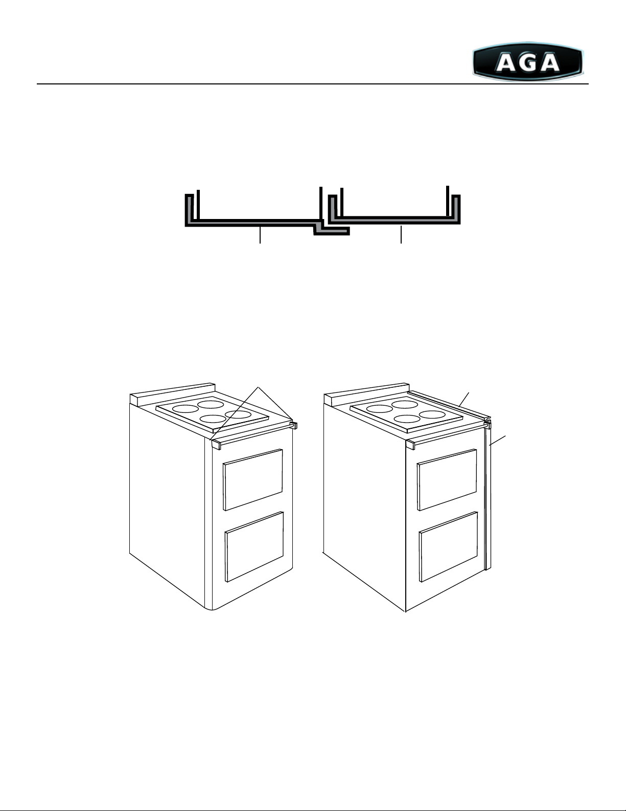
Module vs. Companion vs. Hotcupboard
The Module
The module attaches to the Cooker and must be ordered together with the Cooker.
The Cooker Front Plate and the module front overlap. When ordering a Module and Cooker the fronts are factory matched.
Modules can be ordered with all Cooker options. The module cannot be used as a freestanding range.
Module Cooker
Front Plate Front Plate
The Companion
The Companion is a freestanding range that does not physically attach to the Cooker. The companion may be put in proximity to the
Cooker but will need division from the Cooker as the front and top will not marry.
Companion
Front wraps
around sides
Top overlap
to Cooker
Front overlap
to Cooker
Module
Note: Drawing for illustration of front plate only and does not adequately portray all product details.
Hot Cupboard
The term “Hot cupboard” is used to describe the left two ovens of a 4 oven Cooker.
The “Hot cupboard” is shipped (although packaged separately) as an integral part of a 4 oven Cooker and does not need to be ordered
separately.
The “Hot cupboard” can not be used as a freestanding range.
Due to continuing product improvements, AGA Marvel reserves the right to amend specifications without notice. Please contact AGA Marvel for the most up to date
information, as it applies to product being purchased, or download the latest Design Guide from www.aga-ranges.com.
27
Page 28

Specifications: Companion
Freestanding Companion Only
Overall height 35 7/8” (91.12cm)
Overall width 23½” (60cm)
Overall depth 23¾” (61cm)
Weight 310lbs. (141kg)
2 Oven with Module
Overall dimensions 33½” 86cm) H x 63”(160cm) W x 26¾”(67.9cm) D without bar (29¾”(76cm) with towel bar)
Weight 1210lbs. (549kg)
3 Oven with Module
Overall dimensions 33½”(86cm) H x 63”(160cm) W x 26¾”(67.9cm) D without bar (29¾”(76cm) with towel bar)
Weight 1394lbs. (634kg)
4 Oven with Module
Overall dimensions 33½”(86cm) H x 8219/32”(209.78cm) W x 26¾”(67.9cm) D without bar (29¾”(76cm) with towel bar)
Weight 1600lbs. (725kg)
Burner Ratings
Right front 12,000 BTU
Right rear 6,150 BTU
Left front 6,150 BTU
Oven Ratings
Top Zoned heat with 7 pass, 2,100 watt broiler
Bottom Convection
Oven Dimensions
Top 8½” (22cm) H x 13” (33cm) W x 19” (49cm) D
Bottom 10” (25cm) H x 13¾” (35cm) W x 17” (43cm) D
Oven Capacity
Top 1.5 cu. ft.
Bottom 1.5 cu. ft.
Total capacity 3.0 cu. ft.
Electrical Requirements 240 volts, 30 amp dedicated circuit
Fuel type Natural gas or LPG with electric ovens
Gas connection ½” female N.P.T.
Color options Cream, Claret, Black, dark Blue, British Racing Green, Pewter, White, Aubergine Heather,
Pistachio, Wedgewood, Chocolate, Jade
Hood requirement 300 CFM hood
Warranty 5 year on materials and workmanship. 1 year on mechanical components, parts and labor.
Due to continuing product improvements, AGA Marvel reserves the right to amend specifications without notice. Please contact AGA Marvel for the most up to date
information, as it applies to product being purchased, or download the latest Design Guide from www.aga-ranges.com.
28
Page 29

Companion Dimensions & Requirements
3”
(7.62cm)
Appliance can be close
fitted to kitchen units
up to work top height
23½”
(60cm)
Overhead
Cupbored
3”
(7.62cm)
37⅜”
(95cm)
28” Min
(71cm)
35¾”
(91cm)
13” Max.
(33cm)
23¾”
(60cm)
26¾”
(68cm)
42½”
(108cm)
Due to continuing product improvements, AGA Marvel reserves the right to amend specifications without notice. Please contact AGA Marvel for the most up to date
information, as it applies to product being purchased, or download the latest Design Guide from www.aga-ranges.com.
29
Page 30

Legacy (Aleg Models)
Planning Information
e following specications provide overall dimensions, nished rough opening dimensions and gas/electrical requirements for the
Legacy dual fuel and electric range models. Please follow these guidelines when planning your installation to avoid damage to your range
and/or surrounding cabinetry. Refer to the installation guide included with your range for specic installation instructions.
Please be sure to consult a qualied electrician and ensure the installation conforms to all national and local electrical codes and gas
regulations.
Electrical Requirements
e electrical connection is located at the center rear of the unit.
is appliance requires 240 volt, 60Hz and connected to an individual, properly grounded branch circuit protected by a circuit
breaker or time-delay fuse.
Amperage Draw Max Draw
Legacy 36” (dual fuel models) 30.8 Amps 7.4 kW max load 240 volt
Legacy 44” (dual fuel models) 30.8 Amps 7.4 kW max load 240 volt
Legacy 36” (electric models) 64.58 Amps 15.5 kW max load 240 volt
Legacy 44” (electric models) 69.58 Amps 16.7 kW max load 240 volt
It is supplied with a 4-prong plug to be used in a NEMA 14-50 receptacle. Orient the receptacle so the length is parallel to the
oor. (See gure 1)
Recommended acceptable electrical outlet area. Orient the electrical receptacle so the length is parallel to the oor.
Important: Electrical grounding is required on
this appliance.
Warning!: is appliance must be completely
isolated from electrical supply prior to servicing.
12” (31cm) min
(Fig. 1)
Electrical
connection
cover
(Fig. 2)
Due to continuing product improvements, AGA Marvel reserves the right to amend specifications without notice. Please contact AGA Marvel for the most up to date
information, as it applies to product being purchased, or download the latest Design Guide from www.aga-ranges.com.
30
Page 31

Gas Requirements
e installation of this range must conform with local codes, or in the absence of local codes, with National Fuel Gas Code, ANSI
Z223.1-latest edition. In Canada the range must be installed in accordance with CGA Standard CAN/CGA-B-149 Installation Codes for
Gas Burning Appliance and Equipment and/or local codes. In the Commonwealth of Massachusetts, this product must be installed by a
licensed plumber or gas tter.
e gas feed is located on the left-hand rear of the unit. e appliance is supplied with a ½” female NPT tting.
Gas Pressure 10” w.c. LPG
4” w.c. NG
e range is supplied set for natural gas. An LPG conversion kit is included.
e gas supply should exit the wall in the shaded area as shown in Figure 2. e appliance can be installed with an approved
exible connection. e supply piping should be no less than ⅜” I.D. exline.
Important: A “T” handle type manual shut-o valve must be tted before the metal gas exi line in an accessible location.
Do not t valve behind range.
7” (18cm)
minimum - will vary
with adjustment of feet
Gas inlet
Electrical
connection
cover
Due to continuing product improvements, AGA Marvel reserves the right to amend specifications without notice. Please contact AGA Marvel for the most up to date
information, as it applies to product being purchased, or download the latest Design Guide from www.aga-ranges.com.
31
Page 32
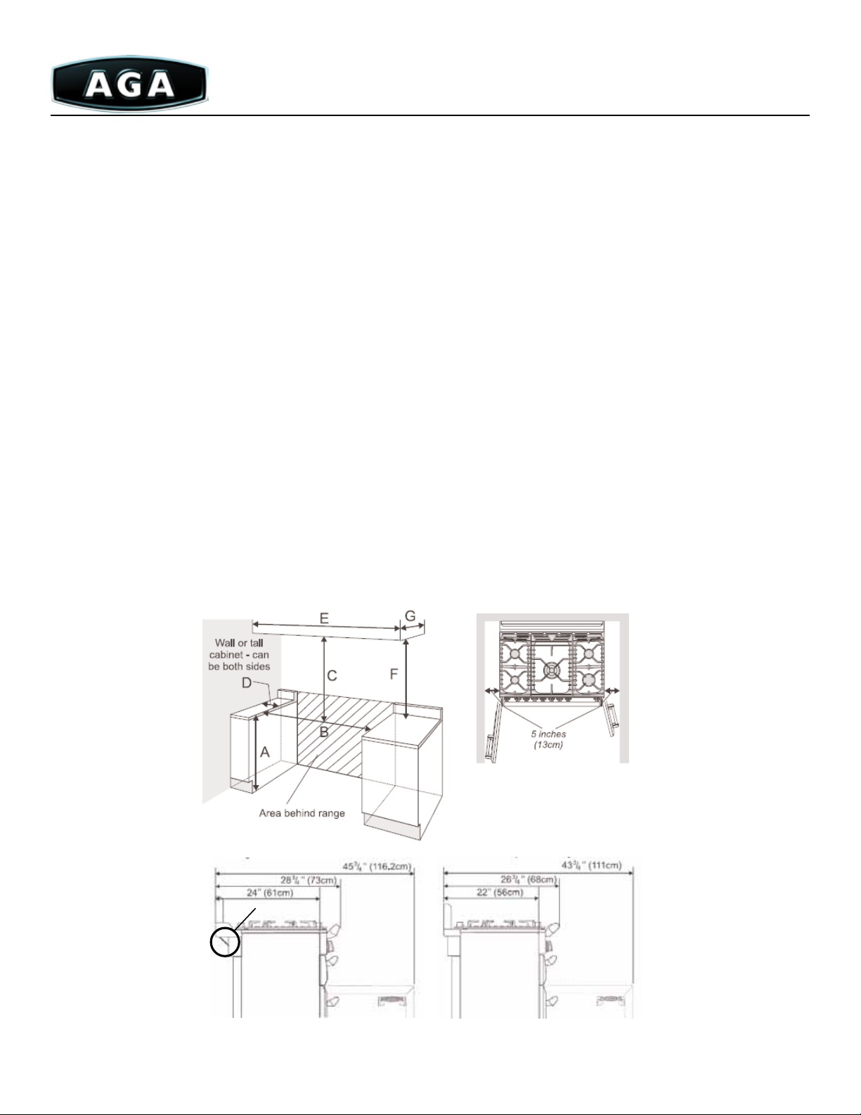
Unit Placement
Provide adequate clearances between the range and adjacent combustible surfaces. ese dimensions must be met for safe use of
your range.
e cooktop surround should be level with, or above, any adjacent work surface. Above cooktop level a gap of 3”(8cm) should
be left between each side of the range and any adjacent vertical wall. For noncombustible surfaces (such as unpainted metal or ceramic
tiles) this can be reduced to 1”(2.5cm). A minimum space of 30” (76cm) is required between the top of the cooktop and a horizontal
combustible surface. e maximum depth for cabinets installed above cooktops is 13” (33cm). A clearance of 5” (13cm) is required if the
range is near a corner of the kitchen to allow the oven doors to open.
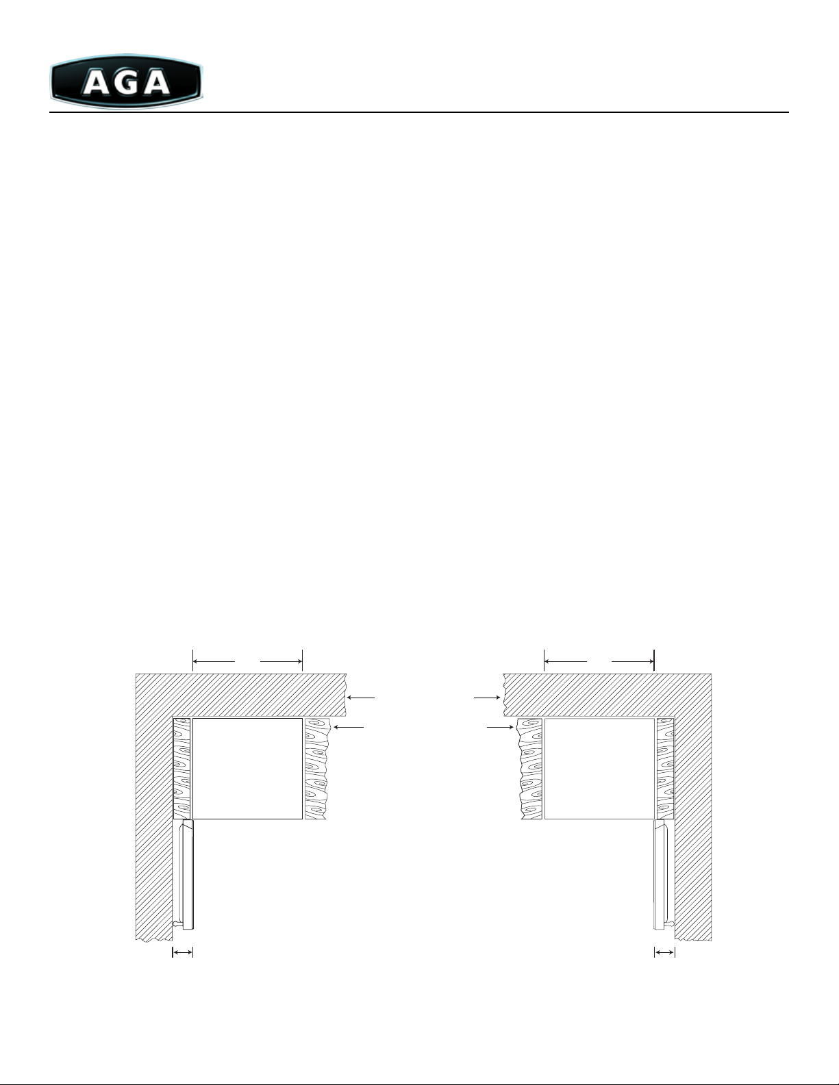
36” Model - We recommend a gap of 35 13/16” (91cm) (for Canada min 35 7/16”(90cm)) between units to allow moving of the
range. If a ush t is required (USA only), r the range up to the unit at one side then t the unit to the other side.
44” Model - We recommend a gap of 43 5/16” (110cm)(for Canada 44 5/16”(113cm)) between units to allow for moving the
range. If a ush t is required (USA only), t the range up to the unit at one side then t the unit to the other side.
Legacy 36” Legacy 44”
A. Min 35⅜”(91cm) - Max 36 7/16” (92cm) A. Min 35⅜”(91cm) - Max 36 7/16”(92cm)
B. Min 35 3/16”(90cm) (for Canada - Min 36 7/16”(92cm)) B. Min 43 5/16”(110cm) (for Canada- Min 44 5/16”(113cm))
C. Min 30”(76cm) C. Min 30”(76cm)
D. Min. 3” (8cm)(see below about door opening.) D. Min 3”(8cm)(See below about door opening.)
E. Min. 42½”(108cm) E. Min 50” (127cm)
F. Min 18” (46cm) F. Min 18” (46cm)
G. Maximum 13” (33cm) G. Maximum 13” (33cm)
with spacer
without spacer
Due to continuing product improvements, AGA Marvel reserves the right to amend specifications without notice. Please contact AGA Marvel for the most up to date
information, as it applies to product being purchased, or download the latest Design Guide from www.aga-ranges.com.
32
Page 33

Specifications
Legacy 36” Legacy 44”
Overall width 35½” (90cm) 43¼” (110cm)
Overall depth 25⅝” (66cm) 25”⅝ (66cm)
Overall height 35⅜” (91cm) 35⅜” (91cm)
Weight 300lbs (136kg) 341lbs (155kg)
Burner Ratings
Left & right rear 9,200 BTU NG, 8,000 LPG 15,000 BTU NG, 15,000 LPG
Left front 5,000 BTU NG, 4,200 LPG 5,000 BTU NG, 4,200 LPG
Center 15,000 BTU NG, 15,000 LPG N/A
Left & right center N/A 9,200 BTU NG, 8,000 LPG
Right front 12,000 BTU NG, 12,000 LPG 12,000 BTU NG, 12,000 LPG
Oven Capacity
Top left oven 0.5 cu. ft. 0.5 cu. ft.
Bottom left oven 2.2 cu. ft. 2.2 cu. ft.
Right oven 1.8 cu. ft. 2.4 cu. ft.
Total Capacity 4.5 cu. ft. 5.1 cu. ft.
Internal Oven Dimensions
Top left oven 15¾”(40cm)D x 13”(33cm)W x 4½”(11cm)H Same
Bottom 15¼”(39cm)D x 14¾”(38cm)W x 17”(43cm)H Same
Right oven 15¼”(39cm)D x 9½”(24cm)W x 22¼”(57cm)H 15¼”(39cm)D x 16”(41cm)W x 17¼”(44cm)H
Dual Fuel Model Requirements
Electrical Requirements 240 volts 240 volts
Fuel Types Natural Gas or LPG with electric ovens Same
Gas Connection ½” female N.P.T. Same
Electric Model Requirements
Electrical Requirements 240 volts Same
Colors Cream, Brick, Black, Cobalt Blue, White, Stainless Steel, and All White
Hood requirement Maximum 600 CFM hood
Warranty 5 year on materials and workmanship. 1 year on mechanical components, parts and labor.
Options Cathedral Window Door - window on MultiFunction™ oven door. (Specify when ordering)
Classic Handle - replaces spiral handle with straight bar-type handle. (Specify when ordering)
Concealer Panel - closes gap between the back of the appliance and rear wall for applications at
the end of a cabinet run. (A094590X1)
High Altitude Kit - for applications 5,000 feet and above. (A035182-NG, A035183-LPG)
Due to continuing product improvements, AGA Marvel reserves the right to amend specifications without notice. Please contact AGA Marvel for the most up to date
information, as it applies to product being purchased, or download the latest Design Guide from www.aga-ranges.com.
33
Page 34
Undercounter Refrigeration
(AAR-24, ARD-24, ACIM-15, AWC-24 Models)
Planning Information
e following specications provide overall dimensions, nished rough opening dimensions and gas/electrical requirements for
the undercounter refrigerator, refrigerated drawers, gourmet ice machine and wine cellar models. Please follow these guidelines when
planning your installation to avoid damage to your product and/or surrounding cabinetry. Refer to the installation guide included with
your appliance for specic installation instructions.
Please be sure to consult a qualied electrician and ensure the installation conforms to all national and electrical codes.
Electrical Requirements
Locate a three-prong grounded receptacle in one of three locations:
1. On the wall in the adjacent cabinet opening.
2. Flush on the back of the refrigerator opening (add 1”(2.5cm) to the overall depth of the unit to accommodate plug)
3. Recessed 1”(2.5cm) into the back of the wall of the refrigerator opening.
ese appliances are equipped with a power supply cord with ground. It must be plugged into a mating grounding type receptacle
in accordance with the National Electrical Code and applicable local codes and ordinances.
Unit Placement
Choose a location where the unit will be out of direct sunlight and away from heat sources. Best performance will be maintained
when installed within the following parameters: A gap of 24” (61cm) is recommended between units for moving the appliance. A
clearance of 3” (8cm) is required to the side of the unit that hinges are located on to allow for the door to open 90°.
Adjacent cabinets and countertop can be installed on top, back and sides of the unit as long as the grille and door access remain
unobstructed. Ventilation is required for the bottom front section of the unit where the grille is located. Keep this area open and clear
of any obstructions. Make certain that the leveling legs supplied with appliance are installed according tot he instructions. Leveling
adjustments can be made by raising or lowering the glides on the bottom of the unit.
24”
(61cm)
24”
(61cm)
wall structure
adjacent cabinet
Left Hand Swing
3’’(8cm)
min.
Right Hand Swing
3’’(8cm)
min.
Due to continuing product improvements, AGA Marvel reserves the right to amend specifications without notice. Please contact AGA Marvel for the most up to date
information, as it applies to product being purchased, or download the latest Design Guide from www.aga-ranges.com.
34
Page 35
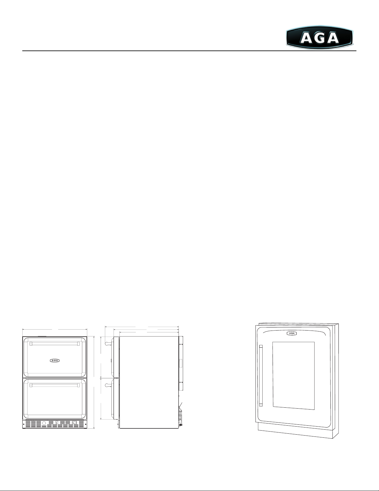
Refrigerated Drawer Wine Cellar
(ARD-24) (AWC-24)
Cabinet Dimensions
Overall height 34” (87cm) 34” (87cm)
Overall width 23⅞” (61cm) 23⅞” (61cm)
Overall depth (including doors) 25¼” (65cm) 25¼” (65cm)
Overall depth (without doors) 22” (56cm) 22” (56cm)
Toe kick 3” (8cm) 3” (8cm)
Rough Opening Dimensions
Height 34½” (88cm) 34½” (88cm)
Width 24” (61cm) 24” (61cm)
Minimum Depth 24” (61cm) 24” (61cm)
Height with leveling legs 34¼” (87cm) - 35” (89cm) 34¼” (87cm) - 35” (89cm)
Min door clearance required 26” (66cm) 25½” (65cm)
Wei ght 180lbs (82kg) 130lbs (59kg)
Capacity 5.7 cu. ft. 6.1 cu. ft.
Electrical requirements 115 volt, 15 amp circuit 115 volt, 60 Hz, 15 amp circuit
Max run amps 3.3 3.3
Max start amps 12.0 12.0
Ideal Ambient Temperature Range
Built-in 55°F (13°C) - 80 °F (27°C) 65°F (18°C) - 80°F (27°C)
Free-standing 55°F (13°C) - 90°F (32 °C) 65°F (18°C) - 90°F (32°C)
27.22
7
23
”
/8
(61cm)
15.13”
(39cm)
34”
(87cm)
15.13”
(39cm)
Due to continuing product improvements, AGA Marvel reserves the right to amend specifications without notice. Please contact AGA Marvel for the most up to date
information, as it applies to product being purchased, or download the latest Design Guide from www.aga-ranges.com.
(69cm)
21.86
(56cm)
24.03
(61cm)
35
Page 36
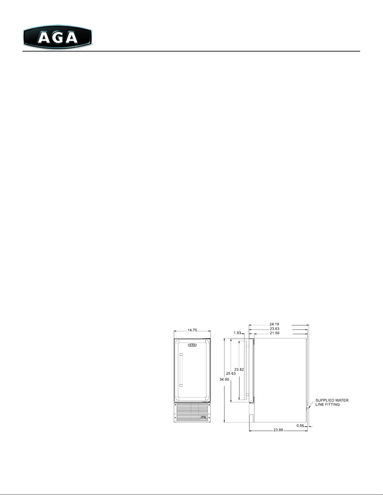
Refrigerator Gourmet Ice Machine
(AWC-24) (ACIM-15)
Cabinet Dimensions
Overall height 34” (87cm) 34¼” (88cm)
Overall width 23⅞” (61cm) 14⅞” (38cm)
Overall depth (including doors) 25¼” (65cm) 21¾” (55cm)
Overall depth (without doors) 22” (56cm) 24⅝” (63cm)
Toe kick 3” (8cm) 3½” (9cm)
Rough Opening Dimensions
Height 34½” (88cm) 34½” (88cm)
Width 24” (61cm) 15” (38cm)
Minimum depth 24” (61cm) 24” (61cm)
Height with leveling legs 34¼” (87cm) - 35” (89cm) 34¼” (87cm) - 35” (89cm)
Min door clearance required 25½” (65cm) 16⅜” (42cm)
Wei ght 120lbs (54kg) 100lbs (45kg)
Capacity 6.1 cu. ft. 35lbs (16kg) of ice
Electrical requirements 115 volt, 60 Hz, 15 amp circuit 115 volt, 60 Hz, 15 amp circuit
Max run amps 3.3 3.3
Max start amps 12.0 12.0
Ideal Ambient Temperature
Built-in 65°F (18°C) - 80°F (27°C) 55°F (13°C) - 80°F (27°C)
Free-standing 65°F (18°C) - 90°F (32°C) 55°F (13°C) - 90°F (32°C)
/ 62cm
/ 60cm
61cm
/ 55cm
2cm
38cm
Due to continuing product improvements, AGA Marvel reserves the right to amend specifications without notice. Please contact AGA Marvel for the most up to date
information, as it applies to product being purchased, or download the latest Design Guide from www.aga-ranges.com.
87cm
66cm
5cm
21cm
36
Page 37
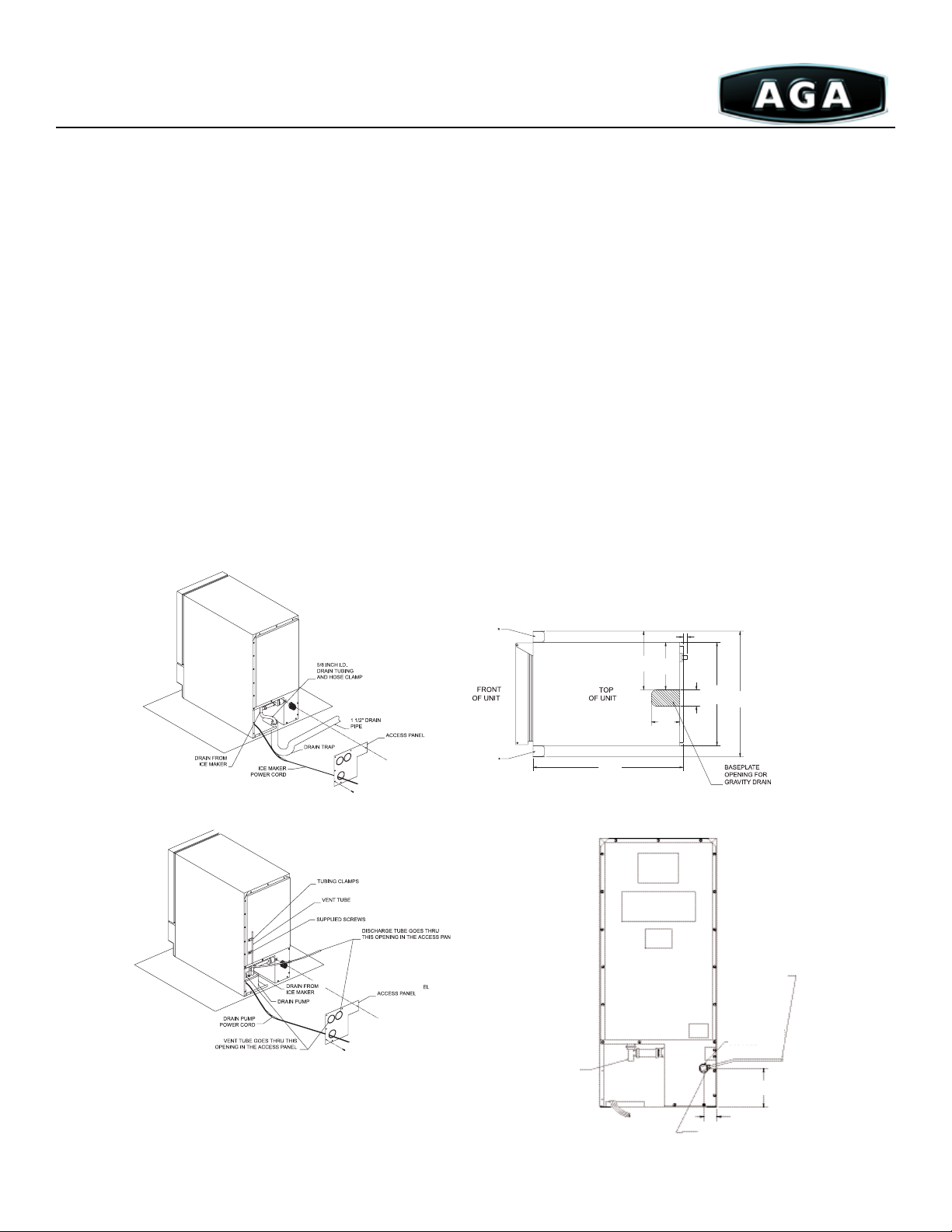
Drain Plumbing for Ice Machine
is appliance uses a gravity drain, (Figure 1) that requires ⅝” I.D. tubing from the back of the unit to a plumbed connection to
a sanitary sewer. Remove the access panel to plumb in drain connection. Gravity drain location for built-in units can be within the area
shown in Figure 3. An optional drain pump, (Figure 2) can be purchased for your ice machine if a gravity drain is not accessible.
Warning!: Failure to use adequate drainage system will result in surrounding water damage and/or poor ice production.
Water Supply
Figure 4 - is is machine must be connected to a potable, active cold water supply line delivering water pressure at a minimum of
20 psi and a maximum of 120 psi.
Water connection is made through a right angle garden hose tting. See garden hose tting for detailed instruction sheet.
A water lter is recommended for this unit. A quality lter can remove particles as well as remove taste and odors from water. Do
not use any thread sealers.
Softened water is not recommended. is will produce mushy, cloudy ice cubes that will stick together.
De-ionized water is not recommended. is water will not form solid ice cubes.
A water specialist can recommend proper water treatment.
After installation of water line, turn on water and check for any leaks. Additional tightening may be needed.
Allow for extra water line built-in installations for easy removal of unit and to help prevent the water line from kinking.
Fig 3
.56” / 2cm
8.37”*
6.75”
22cm
18cm
14.75”
2.38”
18”*
38cm
7cm
46cm
4.06”
11cm
21.50”
55cm
Fig 1
Fig 4
Rear of unit
Fig 2
5/8” I.D. Drain
tubing barb
make certain all hose
clamps are secure
Due to continuing product improvements, AGA Marvel reserves the right to amend specifications without notice. Please contact AGA Marvel for the most up to date
information, as it applies to product being purchased, or download the latest Design Guide from www.aga-ranges.com.
1/4” (.7cm)
Tubing from
cold water line
Garden hose
fitting
2.13” / 6cm
Compression fitting
5.50”
17cm
37
Page 38

Full-size Refrigerator
Overall height 69½” (177cm)
Overall width 36” (92cm)
Overall depth 26½” (68cm)
Overall depth with handle 30” (76cm)
Rough Opening Dimensions
Height 70” (178cm)
Width 36½” (93cm)
Maximum depth 24½” (62cm)
Refrigerator Capacity
Fresh food capacity 12.9 cu. ft.
Freezer capacity 5.6 cu. ft.
Total capacity 18.5 cu. ft.
Electrical requirements 115 volts, 60 Hz, 15 amp circuit
Ideal ambient temperature 55°F (13°C) - 110°F (43°C)
Due to continuing product improvements, AGA Marvel reserves the right to amend specifications without notice. Please contact AGA Marvel for the most up to date
information, as it applies to product being purchased, or download the latest Design Guide from www.aga-ranges.com.
38
Page 39

Dishwasher
Overall height 33⅞” (86cm)
Overall width 23⅞” (61cm)
Overall depth (including handle) 24⅞” (63cm)
Overall depth (without door) 22
7
/16” (57c m)
Rough Opening Dimensions
Height 34” (87cm)
Width 24” (61cm)
Depth 24” (61cm
Depth (open door) 45” (114cm)
Electrical Requirements 120 volts, 60 Hz, 12 amp circuit
Due to continuing product improvements, AGA Marvel reserves the right to amend specifications without notice. Please contact AGA Marvel for the most up to date
information, as it applies to product being purchased, or download the latest Design Guide from www.aga-ranges.com.
39
Page 40
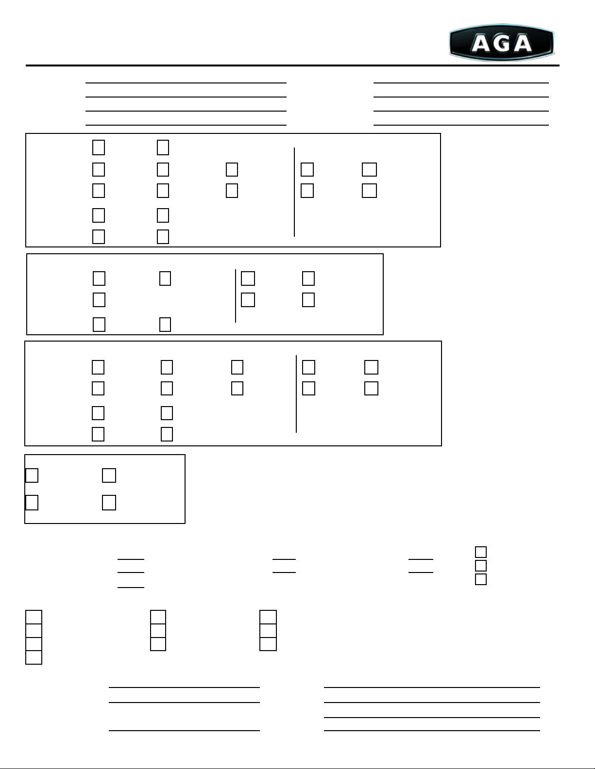
Site Requirements Checklist
1260 East Van Deinse Street Greenville, MI 48838
Dealer Name: Customer Name:
Address: Address:
Phone: Phone
4 Oven:
Fuel Options - Natural Gas Liquid Propane Electric Yes No
Venting - Standard Vent Direct Vent Power Vent Natural Gas Liquid Propane
*Piping Listed Below
Classic - Yes No *Attaches to Cooker
Color Match Lids - Yes No
Hotplate Gas Hob
Module*:
3 Oven: Module*:
Fuel Options - Natural Gas Liquid Propane Yes No
Venting - Standard Vent Natural Gas Liquid Propane
* Piping listed below
Color Match Lids - Ye s No *Attaches to Cooker
2 Oven: Module*:
Fuel Options - Natural Gas Liquid Propane Electric Yes No
Venting - Standard Vent Direct Vent Power Vent Natural Gas Liquid Propane
* Piping listed below
Classic - Ye s No *Attaches to Cooker
Color Match Lids - Yes No
Companion: Colors (Circle Selection):
Yes No Standard Colors - Black British Racing Green Pewter
Cream Dark Blue Pearl Ashes
Natural Gas Liquid Propane Signature Colors - Aubergine White Heather
Duck Egg Blue Pistachio
For Standard Vent Units - Black Enameled Steel Pipe:
P1020 – 4” x 24” piece(s) P1021 – 4”X 36” piece(s) P1149 – 4” x 48” piece(s)
P1141 – 45° bend no door piece(s) P1050 – 45° bend w/door piece(s) A4136 – Sealing Ring piec(s)
P1095 – 90° Elbow w/door piece(s)
Fitter Conrmation (Initial where indicated):
Floor Structure Venting Gas Installation
Electrical Installation Custom Hearth Set Back and Combustibles
Heating/Cooling Load Vent Hood Priority of Installation
Clearance around the AGA
Fitter Name: Notes:
Phone:
Please indicate who is supplying:
Fitter Stock
Distributor Stock
Order with Cooker
Site Inspection Done By Sales Rep (dealer):
Copy to: Fitter, Dealer, Distributor. A copy of this form must also accompany Cooker order to AGA Marvel.
AG-9991 110912
Page 41
Design Considerations
1. Floor Strength: The AGA sits flat on the floor,
spreading the weight over 10 square feet for the 4-oven
model (1,290 lbs.) and 7 square feet for the 2-oven
(900 lbs.) Review the Floor supports. (Ordinarily not a
problem).
2. Heat Loads: Most kitchen appliances radiate heat. i.e.,
commercial-style refrigerators (300-900 BTU/hr.) AGA
Cooker (3,000 BTU/hr. or 3 tonnes), commercial-style
cookstoves (12,000/burner - 40,000/oven BTU/hr. when
operating), overhead light spots (12x100 watt bulb at
approximately 300 BTU/hr.) Orientation, solar gain, and
room dimensions should also be considered.
3. Air Conditioning/Ventilation: Cross ventilation
should be considered in the kitchen design as well as any
air conditioning. A certified heating and cooling engineer
will be able to determine your needs.
4. Work Space: It helps to have space on each side of
the AGA on which to set hot pots. The left side of the
4-oven may not require extra space because of the
warming plate.
5. Hood: No hood is required under the American or
Canadian Gas Association Certifications. However, many
owners will include one for looks or for extracting air
for the occasional, brief cooking on top of the stove, or
for low-volume room air ventilation.
Site Descriptions:
6. Cabinets Over the AGA: Flue pipe going through a
cabinet must be Type B. Cabinets over the AGA must be
30” above the cook top and may not project more than
13” from the wall.
7. Side Cabinets: Zero clearance on each side. Consider
a narrow cabinet on the left to house the roasting pan,
cookie sheet, or grill rack. If the gas lead is out of the left
side, this gives a hidden work area routing the pipe or
possible shut-off.
8. Platform/Hearth: Face treatment should be planned
into the final dimensions of the hearth: tile, brick, etc.
Page 1 covers these details.
9. Routing Vent Pipe: (Applies to Standard Vent and
Power Vent only) Please don’t wait until the last minute
to accommodate the vent pipe, because you can lose
options. The Standard Vent unit must extend above the
roof. Be sure to review any building code requirements
before proceeding.
Due to continuing product improvements, AGA Marvel reserves the right to amend specifications without notice. Please contact AGA Marvel for the most up to date
information, as it applies to product being purchased, or download the latest Design Guide from www.aga-ranges.com.
41
Page 42

Design Considerations
10. Gas Supply Line: Building codes will apply. The gas
feed connection can exit the AGA either left, right or, in
some cases, throught the f loor into the basement. Plan
the lines early so as not to lose options. An additional
gas connection will be needed if a Companion is being
installed with the AGA. Call your fitter or AGA dealer for
details.
11. Work Island: The radiant heat from the AGA travels in
the line of sight and diminishes rapidly with distance.
Consider the location of an island for greatest comfort, 48”
is recommended.
12. Electrical Requirements: No electricity is required for
Standard or Direct Vent cookers. For Power Vent, see the
electrical requirements on Page 9 for details. If an AGA
Companion is to be installed with your AGA, it will need
240-volt, 30-amp service. Contact your fitter or AGA
dealer for details.
Site Descriptions:
Important Contacts
AGA Dealer
AGA Installer
Kitchen Designer
Builder/ Contractor
Gas Supply Company
Due to continuing product improvements, AGA Marvel reserves the right to amend specifications without notice. Please contact AGA Marvel for the most up to date
information, as it applies to product being purchased, or download the latest Design Guide from www.aga-ranges.com.
42
Page 43
Our Family of Premium Brands
United States
AGA MARVEL
1260 E Van Deinse Street
Greenville, MI 48838
800-223-3900
www.AGAmarvel.com
© AGA MARVEL 2012, all rights reserved.
AG-9991 - 110912
The informaon presented herein is based on the best data available at me of
prinng and is believed to be correct. However, nothing stated herein is to be taken as
warranty, expressed or implied, regarding the accuracy of the informaon or the use
of our product or products. Products might not appear exactly as shown in images.
Specicaons and product esthecs are subject to change without noce.
AGA MARVEL - SOFA Galleries
6900 Airport Road, Suite 205
Mississauga ON, L4V 1E8
Canada
855-213-2785
 Loading...