

Page 1

12/17 EINS 516870
AGA 60 Electric
For use in GB and IE
PLEASE READ THESE INSTRUCTIONS BEFORE USING THIS APPLIANCE
AND KEEP IN A SAFE PLACE FOR FUTURE REFERENCE.
User Guide &
Installation Instructions
CAUTION: THIS UNIT IS HEAVY, PROPER EQUIPMENT AND ADEQUATE MANPOWER MUST BE USED IN MOVING THE
RANGE TO AVOID DAMAGE TO THE UNIT OR THE FLOOR.
REMEMBER, when replacing a part on this appliance, use only spare parts that you can be assured conform to the safety and
performance specication that we require.
DO NOT use reconditioned or copy parts that have not been clearly authorised by AGA.
Page 2

Make a note of your AGA appliance Serial Number when it is being installed.
The serial number can be found behind the plinth cover.
My AGA Details:
Serial No:
AGA Service No:
Date of Installation:
Page 3

1. Health and Safety 1
2. Introduction 2
3. Overview 3
Control panel 4
Cooker hoods and oven venting 4
General advice 5
Using the zones of the AGA 60 5
Hotplate control 5
The boiling plate setting 5
The simmering plate setting 5
The resting plates 6
The ovens 6
4. AGA accessories 7
Roasting oven setting 9
Baking oven setting 9
Simmering oven 10
5. Oven shelves 11
6. Cooking table 12
7. Cleaning & Caring for
your Cooker 13
8. Servicing 15
9. Installation instructions 16
10. Installation introduction 17
11. Removal from pallet and
appliance installation 18
12. Specifications 20
13. Electrical connection 24
14. Control knob and
handrail connection 25
15. Circuit diagram 26
16. Checklist 27
Contents
Page 4

Page 5

1. Health and Safety
CHILDREN SHOULD BE KEPT AWAY FROM THE
APPLIANCE AS SOME SURFACES CAN BECOME HOT
TO THE TOUCH.
The appliance may contain some of the materials that are
indicated below. It is the Users/Installers responsibility to
ensure that the necessary personal protective clothing
is worn when handling where applicable, the pertinent
parts that contain any of the listed materials that could be
interpreted as being injurious to health and safety, see below
for information.
Glues and Sealants
Exercise caution - if there are still in liquid form use face mask
and disposable gloves.
Glass Yarn, Mineral Wool, Insulation Pads, Ceramic Fibre
May be harmful if inhaled. May be irritating to skin, eyes,
nose and throat. When handling avoid contact with skin or
eyes. Use disposable gloves, face-masks and eye protection.
After handling wash hands and other exposed parts. When
disposing of the product, reduce dust with water spray,
ensure that parts are securely wrapped.
General
NEVER place anything aluminium between the
saucepan base and the ceramic surface (i.e. cooking
mats, aluminium foil, etc).
IMPORTANT: Oil is a re risk, do not leave pans
containing oil unattended.
• In the event of a fire cover witha lid and switch OFF the
electricity.
• Smother the flames on the hob rather than attempting
to remove the pan to the outside.
• Burns and injuries are caused almost invariably by
picking up the burning pan to carry outside.
Deep Fat Frying
• Use a deep pan, large enough to completely cover the
appropriate heating area.
NEVER ll the pan more than one-third ll of fat or
oil.
NEVER leave oil or fat unattended during the
heating or cooking period.
The appliance can be used by children aged from 8 years and
above and persons with reduced physical, sensory or mental
capabilities or lack of experience and knowledge if they have
been given supervision or instruction concerning use of the
appliance in a safe way and understand the hazards involved.
Children less than 8 years of age shall be kept away unless
continuously supervised. Cleaning and user maintenance
shall not be made by children without supervision.
CAUTION: The cooking process has to be supervised.
A short term cooking process has to be supervised
continously.
WARNING: Unattended cooking on a hob with fat or
oil can be dangerous and may result in re. NEVER
try to extinguish a re with water, but switch o the
appliance and then cover ame e.g. with a lid or re
blanket.
WARNING: Danger of re: Do not store items on the
cooking surfaces.
WARNING: Accessible parts may become hot during
use. Young children should be kept away.
WARNING: If the hob surface is cracked, switch o
the appliance to avoid the possibility of electric
shock.
Page 6

2
As responsible manufacturers we take care to make sure
that our products are designed and constructed to meet the
required safety standards when properly installed and used.
Your AGA 60 is a compact cooker which combines the design
values and cooking principles of the traditional AGA with the
exibility to turn each cooking area o and on as you require,
thereby tting into your lifestyle beautifully.
The AGA 60 has been designed to have all the attributes of a
larger AGA within a small space.
Refer to the diagram in the Overview chapter to familiarise
yourself with the product and refer to the relevant sections
for upper oven, lower oven, grill, etc.
IMPORTANT NOTICE: PLEASE READ THE
ACCOMPANYING WARRANTY.
Any alteration that is not approved by AGA could invalidate
the approval of the appliance, operation of the warranty and
could aect your statutory rights.
In the interests of safety and eective use, please read the
following before using your new AGA appliance.
Ensure that the kitchen is well ventilated: keep natural
ventilation holes open or install a mechanical ventilation
device (mechanical extractor hood).
Prolonged intensive use of the appliance may call for
additional ventilation, for example, opening of a window, or
more eective ventilation, for example increasing the level of
mechanical ventilation where present.
Installation must be to local and national wiring regulations
and carried out by a qualied engineer.
A little smoke and some odour may be emitted when rst
switched on. This is normal and harmless (from oven lagging
and starch binder on the element insulation) and will cease
after a short period of use.
2. Introduction
Page 7
3
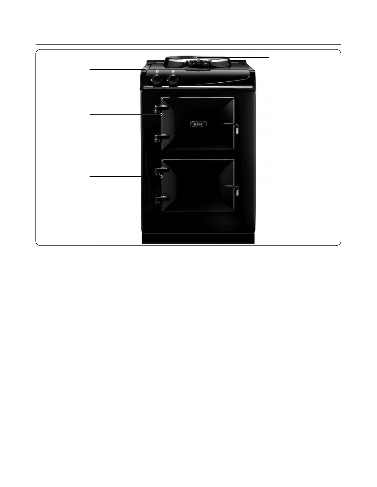
3. Overview
DESN 517541
Fig. 3.1
Cooker overview Fig. 3.1
A. Simmering Plate and Boiling Plate
B. Top Plate and Resting Area
C. Top Oven (Roasting Oven and Baking Oven setting)
D. Simmering oven
B
C
D
A
Page 8

4
Control panel
When switching on the AGA cooker for the rst few times,
there are two things you may notice, neither of which should
cause concern.
The AGA cooker will emit an odour for a short while, this is
simply due to the protective oil we put on the hotplate and
ovens burning o. Due to the newness in the rst couple of
hours, it is advisable to open the kitchen window while this
takes place.
Condensation may occur on the top and front plate whilst the
AGA cooker is heating up, caused by the insulation lagging
and starch binder on the element insulation drying out. The
condensation should be wiped away as soon as possible to
prevent staining the enamel.
Your AGA 60 has the external appearance of a classic AGA
heat storage enamelled cast iron cooker. However, it’s
exibility is almost unbounded because in place of a single
heat source each cooking zone has its own electrically heated
cast iron element (s). The separation of cooking zones, allows
a choice of control. You are able to select only the zones that
you want, or need, to use.
Cooker hoods and oven venting
It is recommended that this AGA is tted with a cooker hood
above it. The AGA venting system is located on top of the
AGA and is designed for venting the moisture from the ovens.
The cooker hood should be positioned not less than the
minimum height as recommended by the manufacturer, from
the top of the AGA.
The AGA 60 ovens are manufactured from cast iron, over a
period of time they will become individually seasoned.
However, the ovens will rust if high moisture content foods
are not covered (especially in the simmering oven) or
spillages are not cleaned up.
It is also not advisable to leave a full or partially lled
saucepan/utensils with high moisture content food in the
ovens when they are not in use.
To season the ovens a light vegetable oil is ideal (corn oil is
best), spray oil is recommended. Any stubborn stains can be
removed with the wire brush supplied.
Cleaning details can be found on “Cleaning & caring for
your cooker” on page 18.
Hobs
OFF
Boiling Setting
Simmering Setting
Oven
OFF
Top Oven
Baking Setting ON
Simmering Oven OFF
Top Oven
Baking Setting ON
Simmering Oven ON
Top Oven - OFF
Simmering Oven ON
Top Oven
Roasting Setting ON
Simmering Oven ON
Top Oven
Roasting Setting ON
Simmering Oven OFF
Page 9

5
General advice
Food should not be placed into any oven until it is up to
normal operating heat.
The oven doors should not be left open for long periods of
time during cooking and heating up.
Store the cold plain shelf outside the cooker. Use it cold in
the roasting oven to deect heat from the top of the oven,
creating a more moderate oven temperature underneath. It
can also be used as a baking sheet.
Warm up times
As the AGA works on the principle of storing heat, time is
required to gather that heat from the electric elements to
saturate the castings. We recommend to allow an hour heat
up time. The optional programmer is a great asset as it can
be set to get the top oven to its working heat, ready for you
to cook when you walk through the door.
The principle of heat storage means that the ovens and
hotplate are at a pre-set heat, the cooking areas are named
after their function rather than temperatures.
Using the zones of the AGA 60
The dierent zones of the AGA 60 cooker are described
individually, in the following pages.
The traditional AGA heat storage cooker is famous for the
gentle warmth it emits, with the AGA 60 you will get warmth
only when the cooker is on or warmth to a lesser degree
when only parts of it are on.
The hotplate
The cast iron hotplate is operated manually and is machined
at to give the best all-over contact with the AGA saucepans,
grill pan, frying pan and kettle.
The boiling plate setting is the hottest with the simmering
plate setting being cooler. It has electric elements embedded
into the cast iron which heat up in approximately 11 and 8
minutes respectively. The hotplate can be used completely
independently from the ovens.
The whole hotplate area can be used for cooking and several
pans can be accommodated on the plate at any one time. The
hotplate is set very slightly above the top plate to minimise
scratching as the pans are pulled to one side to simmer.
The chrome insulated cover is brought down over the
hotplate when it is heating up or not in use. When the
hotplate is ‘ON’ the insulated cover will be warm. We strongly
advise not to put anything such as kettles, saucepans or
baking tins directly onto the insulated cover because it will
show any scratches - invest in a chef’s pad to protect the
surface if the cover is to be used as a resting place!
Keep the hotplate clear of any burnt on food or crumbs
by brushing with the wire brush, supplied with your AGA.
Cleaning details can be found on “Cleaning & caring for
your cooker” on page 18.
Hotplate control
To operate the boiling plate setting turn the control knob to
the position and similarly to the for the simmer plate
setting.
The boiling plate setting
The hottest setting, the boiling plate setting is used for
boiling, grilling, stir-frying, making toast - indeed anything
that requires a high heat. Green vegetables keep their
colour when boiled quickly here, or use a steamer over the
saucepans to cook more than one vegetable at once.
When stir-frying or cooking anything that is inclined to splash
we would recommend using an AGA Splash Shield which will
protect the insulated cover from splatter, making cleaning
a doddle! Just wash the Splash Shield in hot soapy water or
place in a dishwasher between two dinner plates.
Please be advised the boiling plate setting is too hot to cook
food directly on it.
The simmering plate setting
The simmering plate setting is the cooler of the two settings
and so is used for recipes that require a lower heat such as,
making sauces, scrambling eggs, heating milk, slow frying,
simmering soups and root vegetables. In addition, it can
be used to cook on directly as a form of griddle - invaluable
for toasted sandwiches, quesadillas, drop scones, searing
scallops and even a non-fat fried egg! Slow cooked toast can
be made on the simmering plate setting, no need to use the
AGA toaster here.
Page 10
6
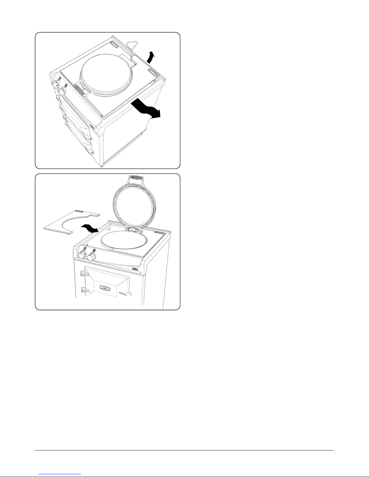
The resting plates
The resting plates are useful when you wish to move a pan o
boil or to a lower temperature.
Take care when removing and replacing the cast iron
resting plates, as they are heavy. Ensure they are cold before
removing.
Removing resting plates
Insert lifting tool in recess at rear of resting plate. Lift up at
rear, the slide out carefully from the side, Fig. 3.2.
Replacement of resting plates
Replace resting plates carefully, as shown in Fig. 3.3.
The ovens
Your AGA 60 has two ovens which are pre-set at a dierent
heat, just like the traditional AGA heat storage cooker. The top
oven has two temperature settings one for the roasting and
one for baking.
Top Oven
• The roasting oven setting for high temperature cooking
• The baking oven setting for moderate temperature
cooking
• The simmering oven for long. slow cooking.
DO NOT OPERATE THIS APPLIANCE WITH THE DOORS
OPEN, SINCE THIS CAN CAUSE A LOCK-OUT.
Each oven has the same capacity, (able to t a 13kg (28lb)
turkey) and the traditional AGA heat-storage cooker
techniques can be used, such as stacking saucepans in
the simmering oven. This enables the steaming of root
vegetables, rice, steamed pudding, casserole, poaching fruit
all in the same oven leaving the hotplate free.
You can have one or two ovens on at their pre-set heat.
The ovens are made from cast iron, which cooks by a radiant
heat and this is the secret of the cooking excellence for which
the AGA cooker is renowned. An indirect radiant heat does
not dry food out, so it retains its natural moisture and avour.
Fig. 3.2
Fig. 3.3
DESN 516889
DESN 516888
Page 11

7
4. AGA accessories
To get the very best performance from your range we
recommend AGA saucepans with the thick tri-core bases and
stacking lids so that the maximum use of oven space is made
and an AGA kettle for boiling water. AGA Accessories can be
viewed at your AGA Specialist or online at www.agacookshop.
co.uk
Getting to know your AGA
If you have not already seen a demonstration, ask your AGA
Specialist for details. A demonstration will show you how
to get the best from your new AGA and will give you hints
and tips. You will also see a selection of AGA utensils and
accessories being used.
Large Size Roasting Tin with Grill Rack (Fig. 4.1)
This is designed to slide onto the oven runners without the
need for it to sit on an oven grid shelf. The roasting tin can be
used with the grill rack, in its high position, for grilling at the
top of the roasting oven. It can be used for roasting meat, or
poultry with or without the grill rack. Large quantities of roast
potatoes can be cooked in this tin. The roasting tin can also
be employed for making large traybakes or cakes. The grill
rack is useful on its own as a cake cooling rack. Can be used in
any oven but not recommended for hotplate use.
Half Size Roasting Tin and Grill Rack (Fig. 4.2)
This tin can be slid onto the oven runners width-ways or can
sit on an oven grid shelf. The half size roasting tin can be
used with the grill rack, in its high position, for grilling at the
top of the roasting oven. It can be used for roasting smaller
joints of meat, or poultry with or without the grill rack. Roast
potatoes can be cooked in this tin. The roasting tin can also
be employed for making traybakes or cakes. The grill rack is
useful on its own as a cake cooling rack. Can be used in any
oven but not recommended for hotplate use.
2 Floor Grid (Fig. 4.3)
This grid is used on the oor of the ovens, in particular the
roasting and simmering ovens to protect food needing over
30 minutes cooking from the intensity of the heat from the
base element.
2 Oven Grid Shelves (Fig. 4.4)
These are for inserting in each oven to provide a surface for
dishes and tins which do not t direct onto the oven runners.
They can be used in any oven, as required.
Fig. 4.1
Fig. 4.2
Fig. 4.3
Fig. 4.4
Page 12

8
Fig. 4.5
1 Cold Plain Shelf (Fig. 4.5)
This has two uses one as large baking sheet for scones,
biscuits, pastry items and meringues and the other use as a
heat deector to cut o the top heat if food is overbrowning
before it is cooked through.
DO NOT STORE IN THE OVENS WHEN NOT IN USE.
Toaster (Fig. 4.6)
This is for toasting bread on the boiling plate. AGA toast is
renowned for its excellence, crisp on the outside and soft in
the centre. Take thick slices of bread and place in the AGA
toaster - if the bread is very moist or very fresh, heat the
toaster beforehand to prevent sticking - lift the boiling plate
insulated cover and place the toaster direct onto the plate
with the handle at an angle from the handle of the cover.
Close the cover and wait for the bread to toast one side this will take 1-2 minutes dependent upon the variety of
bread - open the cover and turn the toaster over and repeat
the process to toast the other side. The toaster can also be
used for heating pitta bread, toasting teacakes and as a cake
cooling rack.
Wire Brush (Fig. 4.7)
This is for cleaning the raw cast iron surfaces, keeping them
clear of crumbs and burnt on debris – which would otherwise
aect the boiling performance of pans and the kettle. Use
on the hotplates and the ovens. Take care not to touch the
enamel surfaces as the wire brush will scratch the nish.
Resting plate lifting tool (Fig. 4.8)
To aid removal of the cast iron resting plates for cleaning.
Getting to know your AGA
If you have not already seen a demonstration, ask your AGA
Specialist for details. A demonstration will show you how
to get the best from your new AGA and will give you hints
and tips. You will also see a selection of AGA utensils and
accessories being used.
Fig. 4.6
Fig. 4.7
Fig. 4.8
Page 13

9
Baking oven setting
The oven is indirectly heated by two elements, one in the
base of the oven and the other in the roof. These elements
heat the air and the cast iron within to provide cooking
results consistent with traditional AGA heat storage cookers,
with the exibility of being able to turn it o when not in use.
This setting is a moderate heat, so is ideal for cakes, biscuits,
also anything that requires medium heat cooking such as sh
pie, lasagne, soués, crumble and roulades. Meat and poultry
can be cooked here indeed most things that can be cooked
on the roasting oven setting can be cooked on the baking
oven setting but for a longer time.
For the best results when cooking cakes do allow at least the
one hour heat up time. Cook cakes together on one shelf. If
two shelves are used interchange the food to achieve even
colouration, as you would with any oven which is zoned heat.
As with the roasting oven setting, the specially designed
roasting tins and bakeware slide directly onto the runners,
so almost every available square centimetre of space can be
used. Food can be protected by the use of the cold plain shelf
or shielded by means of the large roasting tin, which means
that you can cook food that requires dierent temperatures
at the same time. If food is browning too quickly and you do
not want to move it to another oven just slide the cold plain
shelf over the food to reduce the heat.
NOTE: When baking it is always best to start from cold,
otherwise if baking after using the roasting setting the oven
will take a considerable amount of time to cool.
NOTE: Always remove the cold plain shelf and roasting tins
on completion of cooking, if left in the oven it will aect the
oven temperature.
Roasting oven setting
The roasting oven setting is indirectly heated by two
elements, one in the base of the oven and the other in the
roof. These elements heat the air and the cast iron within to
provide cooking results consistent with the traditional AGA
heat-storage cooker, with the exibility of being able to turn
the o when not in use.
The roasting oven setting can be used for ‘grilling’ at the top
and ‘shallow frying’ on the oven oor.
When cooking on the base of the roasting oven, place the
oor grid on the base before putting the food into the oven.
This lifts the food away from the base element to ensure best
cooking results are achieved.
The roasting oven setting is zoned in heat, meaning it is
slightly hotter towards the top than the centre and the oven
grid shelf set on the oven oor is slightly less hot than the
centre.
The base of the oven can be used as another cooking surface,
indeed it is often called a hidden hotplate use the oor grid
for protection so food does not overbrown.
The beauty of the roasting oven setting is that any fat is burnt
o when the oven is at full heat, just brush out occasionally to
remove the carbon deposits.
The roasting oven setting is excellent for bread and pastries.
Quiches in ceramic or pies in Pyrex dishes need not be baked
blind as when they are in placed on the oor grid on the base
of the oven the pastry cooks from underneath and the lling
will set and brown from the all-round heat. As you are aware
metal at tins conduct heat quicker than ceramic may need
less cooking time.
The specially designed roasting tins and bakeware slide
directly onto the runners, so almost every available square
centimetre of space can be used. Food can be protected
by the use of the cold plain shelf or shielded by means of
the large roasting tin which means you can cook food that
requires dierent temperatures at the same time. If food is
browning too quickly and you do not want to move it to
another oven just slide the cold plain shelf over the food to
reduce the top heat.
Page 14

10
Simmering oven
The simmering oven is indirectly heated by one element in
the base of the oven.
This element heats the air and the cast iron within it to
provide cooking results consistent with the traditional
simmering oven of the traditional AGA heat-storage cooker,
with the exibility of being able to turn it o when not
required.
The oor grid is used here to protect items placed on the base
of the oven such as vegetables for steaming, keeping sauces
warm or casseroles cooked for a long time. Always ensure this
is in place, before putting food into the oven.
The simmering oven can be described as a continuation oven,
it continues to cook food that has been brought up to heat
elsewhere on the cooker with the exception of meringues
which are dried out rather than ‘cooked’.
User Guidance
• Allow the oven to heat fully, the longer the oven is on
the better, we recommend one hour.
• To get the very best performance, we recommend to
use AGA cookware with thick bases and stacking lids.
• DO NOT place dishes directly on to the oven base.
Always place onto either a shelf or the floor grid.
• Joints of meat and poultry should be brought up to heat
ideally on the roasting oven setting for 30-45 minutes,
then transfered to the simmering oven.
• This method is unsuitable for stuffed meat and stuffed
poultry).
• Make sure that pork and poultry reach an internal
temperature of at least 75°C.
• Always bring soups, casseroles and liquids to the boil
before putting in the simmering oven.
• Always thaw frozen food completely before cooking.
• Root vegetables will cook better if cut into small pieces.
• Adjust seasoning and thickenings at the end of the
cooking time.
• Many dried pulses and beans for example, dried red
kidney beans must be boiled for a minimum of 10
minutes, after soaking, and before inclusion in any dish.
Page 15

11
5. Oven shelves
Fitting the shelves
Removing the shelves
DESN 512403
DESN 512405
DESN 512404
DESN 512406
Fig. 5.1
Fig. 5.3
Fig. 5.2
Fig. 5.4
Page 16

12
6. Cooking table
Roasting oven setting
Oven temperature = HIGH
Grilling Top - grilling
Scones 2nd runner - scones, small pastries, grilling
Pastries 3rd runner - bread rolls , Yorkshire pudding
Bread 4th runner - roasts, poultry
Yorkshire puddings Oven grid shelf on base of oven - bread loaves, pies, roast vegetables
Roasts Floor grid on base of oven - quiches, pies
Shallow frying
Baking oven setting
Oven temperature = MODERATE
Cakes Towards top - whisked sponges, some biscuits, small cakes
Biscuits
Middle - sh, soués, shepherd and cottage pie, lasagne
Fish
Oven grid shelf on base of oven - Victoria sandwiches, shortbread, traybakes and
cheesecake
Shepherds pie, Cottage pie
Lasagne
Soués
Shortbread
Simmering oven
Oven temperature = LOW
Casseroles
For casseroles, stock, milk puddings and similar dishes bring to heat elsewhere on
the AGA then transfer to the simmering oven (one exception is meringues). Rich fruit
cakes can be cooked here for a, long time on the oven grid shelf placed on the base of
the oven.
Milk puddings
Stock
Meringues
Rich fruit cake
Page 17

13
Always SWITCH OFF at mains before cleaning.
DO NOT use a steam cleaner to clean this cooker.
When cleaning use as little water as possible.
DO NOT use abrasive pads, oven cleaner or cleaners
containing citric acid on enamelled surfaces.
7. Cleaning & Caring for your Cooker
Enamelled Top and Front Plate
The easiest way to clean the AGA top plate and front plate is
to mop up spills as they happen. VEA approved AGA Enamel
Cleaner can be purchased at www.agacookshop.co.uk.
Baked on food is more dicult to clean but can usually be
removed with proprietary vitreous enamel cleaners or mild
cream cleaners using a cloth, or if necessary, a nylon scouring
pad.
If milk or fruit juice, or anything containing acid is spilt on the
enamel, wipe o immediately.
Clean o any condensation streaks on the front plate around
the oven doors or the vitreous enamel maybe permanently
discoloured.
All that is usually needed to keep the vitreous enamelled
surfaces of your cooker bright and clean is a daily rub over
with a damp, soapy cloth followed immediately with a clean,
dry cloth to avoid streaks.
Remember the top plate will scratch if pans or utensils are
dragged across them.
The Ovens
The fan oven is tted with a back panel which is of self
cleaning enamel and should not be scoured.
All of the remaining surfaces of both ovens are vitreous
enamelled and can be cleaned with proprietary vitreous
enamel cleaners approved by the Vitreous Enamel
Association.
The shelves can be removed and if necessary the shelf
supports may also be removed by taking out the screws.
These items may be washed in the sink with normal oven
cleaners, you may use a ne wool soap pad for removing
stubborn stains from the oven bases and shelf supports.
NOTE: Take care not to damage the thermostat
phials in the ovens when cleaning.
Heat Clean Enamel
Fan oven - back panel only
This special enamel has a continuous cleaning action, which
works best if a pattern of low and high temperature cooking
is followed. By using low temperature roasting, excessive
fat splashes can be avoided. Should any excessive staining
occur, immediately clean the area with hot water containing
detergent, and a nylon washing-up brush. Resistant stains
require the oven to be run at 210°C for 2 hours.
DO NOT use any cleaning materials which may clog the
pores of the special coating e.g. pastes and powders,
soap lled pads, spray cleaners, brush-on oven cleaners,
caustic solutions, metal scrapers/knives, and prevent the
cleaning action.
Page 18

14
Door Liners
May be cleaned with a cream cleaner or soap impregnated
pad.
Lift o the oven doors to allow them to cool a little before
cleaning. DO NOT, however, immerse the doors in water
as they are packed with insulating material which will be
damaged by excessive moisture.
Controls
The enamelled surface under the knobs can be treated as in
the Section ‘Door Liners’. Avoid the use of excessive water.
DO NOT use oven cleaners, scouring pads and abrasive
powder for cleaning the plastic knobs. A wipe with a damp
cloth should be sucient.
TIP: Clean your Module regularly, Preferably every time you
use it.
IMPORTANT: AGA recommend Vitreous Enamel Association
approved cleaners for cleaning the vitreous enamelled
surfaces of this product.
Accessories
Oven furniture such as Roasting Tins, Solid Plain
Shelves, Grid Shelves, and Grill Racks should be
cleaned in hot soapy water, soak if necessary, a
nylon scouring pad can be used.
Page 19

15
• To keep your Aga appliance running effciently we
recommend that it is regularly serviced by an Approved
Aga engineer. Approved Aga engineers have been
factory trained and always use genuine Aga spares
• In the event of requiring maintenance, please call AGA
Service or your authorised distributor.
• Your appliance MUST only be serviced by a qualified
engineer from AGA tor an authorised distributor.
• DO NOT alter or modify the appliance.
A hot appliance cannot be serviced.
Service intervals to maintain the appliance warranty are as
follows:
• An interim service is due at 2 ½ years (30 months) to
check and change consumable items, and to undertake
a safety check.
• A full service is due at the end of year 5 (60 months). The
appliance does not cover Commercial use (see separate
warranty book provided for further details).
Spare Parts
To maintain optimum and safe performance, we recommend
that only genuine AGA spare parts are used. These are
available from most major spares stockists, including
ourselves.
8. Servicing
Page 20

16
CAUTION: THIS UNIT IS HEAVY, PROPER EQUIPMENT AND ADEQUATE MANPOWER MUST BE USED IN MOVING THE
RANGE TO AVOID DAMAGE TO THE UNIT OR THE FLOOR.
REMEMBER, when replacing a part on this appliance, use only spare parts that you can be assured conform to the safety and
performance specication that we require.
DO NOT use reconditioned or copy parts that have not been clearly authorised by AGA.
PLEASE READ THESE INSTRUCTIONS BEFORE USING THIS APPLIANCE
AND KEEP IN A SAFE PLACE FOR FUTURE REFERENCE.
9. Installation instructions
DO NOT store or use gasoline or other ammable vapors and liquids in the
vicinity of this or any other appliance.
Installation and service must be performed by a qualied installer or service
agency.
WARNING! This appliance must be installed with an appropriate device that
will allow permanent disconnection of the Live and Neutral conductors. During
Installation or disconnection prior to any electrical work, the appliance must be
permanently disconnected from the Supply (Live) and Neutral Conductors.
WARNING!
Please read the Warning, Cautionary notes at the start of this section.
If the information contained within these instructions is not followed,
property damage or personal injury may occur.
Page 21

17
Consumer protection
As a responsible manufacturer, we take care to make sure
that our products are designed and constructed to meet the
required safety standards when properly installed and used.
Refer to the “Checks for the installer” on page 17 to test
the operation of appliance.
This appliance is not connected to a combustion products
evacuation device. It shall be installed and connected in
accordance with current installation regulations. Particular
attention shall be given to the relevant requirements
regarding ventilation (B.S. 5440).
It should be in accordance also with any relevant
requirements of the Gas Region and Local Authority.
WARNING - ELECTRIC SHOCK HAZARD
It is the customers responsibility to contact a qualied
electrical installer to make sure the electrical installation is
adequate and in conformance with the regulations.
Take special care when cutting holes in walls or oor.
Electrical wires may be behind the wall or oor covering and
could cause an electrical shock if you touch them.
Locate any electrical circuits that could be aected by the
installation of this product and disconnect power circuit.
WARNING: This appliance must be earthed.
DO NOT use an extension lead with this appliance.
10. Installation introduction
Checks for the installer
Check with a qualied electrician if you are not sure the
appliance is properly earthed.
Failure to follow these instructions could result in death or
serious injury.
Check oven elements heat up and that ovens reach
temperature.
WARNING: THIS APPLIANCE MUST BE EARTHED.
The appliance is designed for the voltage stated on the data
plate.
Page 22

18
11. Removal from pallet and appliance installation
1. Removing of transit brackets - Unscrew 4 screws and
remove brackets, from front and two screws from rear
(Fig. 11.1).
2. NOTE: Care must be taken not to trap mains cable.
Appliance to be removed from rear of pallet only.
Recess provided for suitable sack truck. Appliance to be
secured to sack truck with suitable straps (shaded area)
(Fig. 11.2).
3. Once appliance is in position in kitchen, remove sack
truck and straps. The front stability feet can be raised
with a spanner to allow appliance to be slid from transit
pallet (Fig. 11.3).
4. Slide cooker o transit pallet. Take care not to trap
mains cable (Fig. 11.4).
DESN 517176
Fig. 11.1
DESN 516891
DESN 517177
DESN 517178
Fig. 11.2
Fig. 11.3
Fig. 11.4
MAINS CABLE
STABILITY FOOT
Page 23

19
DESN 516894
DESN 516895
DESN 516897
DESN 516898
Fig. 11.5
Fig. 11.6
Fig. 11.7
Fig. 11.8
5. Appliance can now be pushed back on its wheels into
desired position. NOTE: Care must be taken not to trap
mains cable (Fig. 11.5).
6. Levelling of appliance - Use 13mm socket to adjust
wheel mechanism for FINE adjustment on both sides at
rear of the appliance (Fig. 11.6).
7. Using a 12mm open end spanner, feet can be adjusted
at front to make FINE adjustments to the front of the
appliance and to provide a brake for the wheels (Fig.
11.6).
8. Turning the bolt clockwise will lower the wheel thus
increasing height of the cooker (Fig. 11.6).
9. Anti-clockwise lifts the wheels and lowers the cooker
(Fig. 11.6).
10. Fit the magnetic plinth (Fig. 11.7)
11. Resting Plate Adjustment - Resting plates have
adjuster screw feet for setting of height and to improve
stability (Fig. 11.8).
FRONT PLINTH COVER FITS
OVER SIDE SKIRTS
MAKE SURE SIDE PLINTH
SKIRTS ARE LOCATED IN
FRONT GUIDE BRACKET
Page 24

20
12. Specifications
Fig. 12.1
Clearances for overhead cupboards - Fig. 12.1.
NOTE: When surveying for a appliance installation the actual clearance required for the ‘body’ of the appliance should be
increased overall by 10 mm (⁄) beyond the gures quote above. This allows safe margin to take into account the natural
dimensional variations found in major castings in particular the width across an appliance recess could be critical.
Appliance weight (Excludes packaging)
Model: AGA 60 Electric 492 lbs (223 kg)
DESN 516872
Page 25

21
Side Clearances
If you are installing the appliance in a new kitchen or have
the opportunity to set the width between kitchen units, it
is advisable to include an additional small gap each side of
3mm to assist with installation and prevent damage when
moving the product.
A 6mm additional width clearance should also be provided if
the appliance is to go into a brick recess, to allow for the wall
being out of square.
Where it is installed against a side wall protruding in the front
of the appliance a 116mm clearance is required on the left
hand side for the oven door access.
Any side wall above the appliance on either side shall not be
less than 60mm horizontally from the appliance (Fig. 12.1).
Surfaces over the top of the appliance must not be closer
than 650mm.
The vent slot in the back of the top plate must not be
obstructed.
Fitting into a 60cm gap
If you are restricted to a 60cm width space, the AGA 60 will t,
subject to the following guide (Fig. 12.2).
The appliance top plate casting width tapers outwards at its
bottom edge. Consequently adjacent cupboard units should
have a maximum depth of 595mm (including doors). If they
are deeper, bring the appliance forward.
The thickness of adjacent worktops should not exceed 45mm.
Appliance Base or Hearth
It is essential that the base or hearth on which the appliance
stands should be level and be capable of supporting the total
weight of the appliance.
The front plinth cover is removable and must not be
obstructed by ooring or tiles. If necessary the appliance
must be raised by the thickness of the tiles to ensure the
plinth can be removed, and the appliance can be rolled out
for service.
Tiling
When the appliance is to stand in a recess or against a wall
which is to be tiled, in no circumstances should the tiles
overlap the appliance top plate, access to remove the top
plate must be allowed for servicing at a later date.
Option Pre-heat Timer Kit (AE4M231659)
If the optional pre-heat timer kit is tted allowances must be
made for timer location and the cable between the timer and
appliance. Timer cable is 4 metres.
Fig. 12.2
DESN 516957
Page 26

22
Combustible Rear Walls
Since this appliance can be used continuously, please take
note of the IMPORTANT INSTRUCTIONS.
Where the rear wall is constructed of combustible materials
(such as all-timber or stud wall partitions and batoned
plasterboard) these will require special wall heat protection
measures.
Non-combustible insulation board as a protective cladding
can be used behind the appliance of at least 15mm thick,
such as Monolux or equivalent. This should be taken up to
hotplate level (Fig. 12.3).
Alternatively the cooker can be spaced away from the wall to
create an air gap, using the 25mm spacer brackets supplied
with the cooker (Fig. 12.4).
Fig. 12.3
Fig. 12.4
DESN 516959
DESN 516958
Page 27

23
Fig. 12.5
DESN 516960
The air gap must be left open and NOT blocked o across the
top edge (Fig. 12.5).
SPECIAL NOTE: Ensure that unprotected electric cabling
or plastic services do not pass within or on the outside of
the wall behind or directly above the appliance. This type of
material can age prematurely when exposed to continuous
higher temperature.
Other Clearances
A minimum clearance of 60mm is required above the raised
insulating cover handle.
A minimum clearance of 1000mm must be available at the
front of the appliance to enable it to be serviced.
Page 28

24
The method of connection to the mains electricity supply
must facilitate complete electrical isolation of the appliance,
by a multi-pole switch, having a contact separation of at least
3 mm on all poles.
The isolator should not be positioned immediately above the
cooker, but must be tted within 2 metres of the appliance.
The isolator maybe separate from the connection point.
The mains connection point must be accessible within the
areas shown in Fig. 13.1 and Fig. 13.2 for cable routing
options.
For 2 or 3 phase installations an optional adaptor kit must be
obtained (Part No. AE4M231226).
13. Electrical connection
Fig. 13.1
Fig. 13.2
DESN 516918
DESN 516874 A
SECURE MAINS CABLE USING ‘P’ CLIPS FOR LEFT HAND OR RIGHT HAND CABLE MANAGEMENT.
THE MAINS SUPPLY MUST BE WITHIN THE ZONES SHOWN. IF A RECESSED COOKER CONNECTION IS TO BE
USED BEHIND THE APPLIANCE WITHIN THE HATCHED AREA ALLOW A 5mm GAP AT REAR OF APPLIANCE.
NOTE: If timer kit is tted use the cable tie provided in
timer kit to secure timer cable to mains cable.
WARNING: This appliance must be earthed.
This appliance is designed for the voltage stated on
the rating plate, which is situated behind the plinth
cover.
If the supply cord is damaged, it must be replaced
by the manufacturer, its service agent or similarly
qualied person to avoid a hazard.
A 1PH 30 amp 230V or 3PH 400V minimum 16A per phase
~ 50 Hz fused electrical supply is required adjacent to the
appliance. External wiring to the unit must be installed using
the mains cable provided, in accordance with the current
wiring regulations and any local regulations which apply.
If the cable is shortened, new ferrules must be tted to the
stripped conductors.
1.2 metres
1.2 metres
WORKTOP
Page 29

25
14. Control knob and handrail connection
Fig. 14.1
DESN 516875
Control Knob Location
Ensure control knobs are located onto spindles correctly, as
shown in (Fig. 14.1).
Handrail Location - AGA 60 (Traditional)
Locate handrail onto spindle, lock into position with grub
screws (located on the inside of the bracket).
OVEN
CONTROL KNOB
HOTPLATE
CONTROL KNOB
Page 30

26
15. Circuit diagram
3A
2
2
2
4
2
1
AL NE
P2
O Sim Boil
P3
P4
P5
P6
5
6
7
2
1
P1
P3
5
2
7
6
5
1
3
4
1
3
3
4
2
1
P3
P4
P5
P6
2
21
1
L2
L3 L1 N3N2N1
O Hi SimHi-Sim LoLo-Sim
P3
P1
P2
5
2
1
3
4
600W
2100W
200W
200W
600W
300W
600W
600W
600W
300W
300W
4
4
4
1
3
3
1
B11
32
22
12
B21
B31
1
2
1
2
r
r
b
b
b
b
b
b
b
b
b
bb
b
b
b
b
w
w
w
b
b
b
b
g
b
b
b
bk
bk bk
bk
grgr
gr
gr
gr
gr
gr
gr
r
r
r
r
br
r
w
w
or
or
or
y
y
y
or
or
ww
w
w
w
w
w
w
br
r
r
r
gr
gr
gr
gr
gr
gr
gr
grgr
gr
gr
gr
gr gr
gr gr
grgrgr
gr
gr
gr
gr
b
b
b
b
b
gr
gr
gr
r
v
v
r
gr
gr
gr gr gr
g
y
b
b
b
b
gr
gr
gr
gr
gr
gr
gr
gr
gr
gr
gr
gr
gr
B11 12
22
B21
A1 B1
C1
D1
E1
E2
E3
H2H1
I1
J1
F1
F2
F3
F4
G1
G2
K1
Code Colour
b
Blue
br
Brown
bk
Black
or
Orange
r
Red
v
Violet
w
White
y
Yellow
g/y
Green/yellow
gr
Grey
Code Description
A1
Hotplate overheat thermostat
B1
Hotplate Selector Switch
C1
Hotplate Thermostat
D1
Hotplate Element
E1
Upper Top Element
E2
Upper Oven Base Element
E3
Upper Oven Base Element
F1
Upper Oven Overheat Thermostat
F2
Oven Selector Switch
F3
Upper Oven Thermostat
Code Description
F4
Lower Oven Thermostat
G1
Upper Oven Overheat Switch
G2
Lower Oven Overheat Switch
H1
Hotplate Selector Setting
H2
Oven Selector Setting
I1
Mount Terminal Bracket
J1
Relay Box
K1
Upper Oven Timer
Page 31

27
16. Checklist
Hand these instructions to the user for retention, and instruct in the safe operation of the appliance.
Serial No.
Tick Box / Not
Applicable (N/A)
Check hotplate lid and setting
Check oven door seals, adjust door alignment if necessary.
Baking and Simmering oven rope seals MUST have a gap between the door hinges. The Roasting Oven
is tted with a continuous seal.
Ensure any plastic lm is removed from the inside of the oven doors.
After 30 minutes, check hotplate temperatures (approx).
1. Simmerspot (200 - 250°C)
then hotplate to boiling, after 15 minutes check temperature
2. Hotspot (330 - 380°C)
Turn on roasting and simmering oven, set hotplate to simmer. Raise hotplate lid to avoid staining.
Guide customer through the Users Instructions of the appliance, oering best practices on oven
maintenance, energy usage, enamel cleaning (boiled vegetable water staining on enamel etc.)
Engineer’s Signature ..................................................................... Date ........................................
Page 32

With AGA Rangemaster’s policy of continuous product
improvement, the Company reserves the right to change
specications and make modications to the appliances
described and illustrated at any time.
www.agaliving.com
www.agacookshop.co.uk
Manufactured By
AGA Rangemaster
Station Road
Ketley Telford
Shropshire TF1 5AQ
England
For further advice or information contact
your local AGA Specialist.
 Loading...