

Page 1
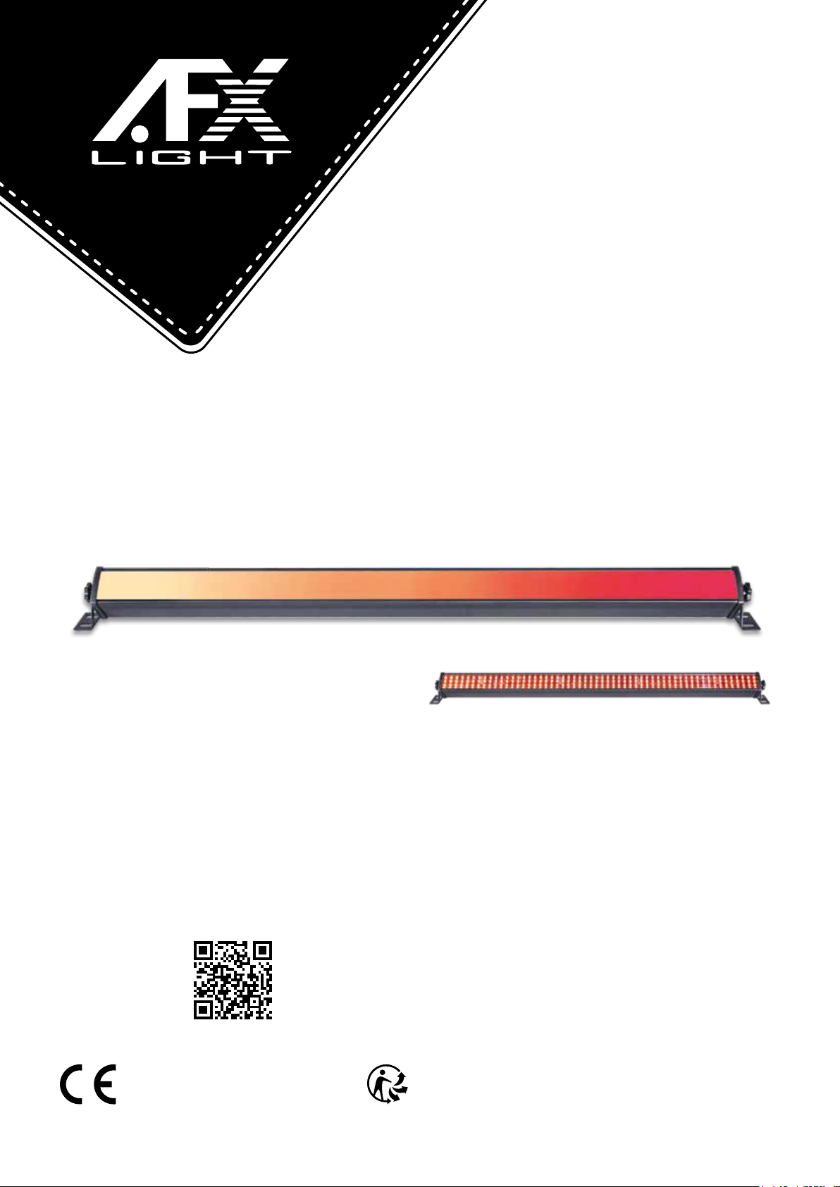
BARLED200-FX
CODE: 16-2706
ANIMATION LED BAR
BARRE D'ANIMATION A LED
ANIMATION LED LEISTE
BARRA DE ANIMACION DE LED
ANIMATIE LED BAR
View the product on our website
Assembled in PRC
Designed by LOTRONIC S.A.
Av. Z. Gramme 9
B - 1480 Saintes
GB - User Manual
F - Manuel d'Utilisation - p. 6
D - Bedienungsanleitung - S. 10
NL - Handleiding - p. 14
E - Manual de Instrucciones - p. 18
DMX Channel Tables - p. 22
Page 2
USER MANUAL
UNPACKING INSTRUCTIONS
Immediately upon receiving a xture, carefully unpack the carton, check the contents to ensure
that all parts are present and have been received in good condition. Notify the freight company
immediately and retain packing material for inspection if any parts appear to be damaged from
shipping or the carton itself shows signs of mishandling. Keep the carton and all packing materials. In the event that a xture must be returned to the factory, it is important that the xture be
returned in the original factory box and packing.
CONTENTS OF THE CARTON
• 1 pc. BARLED200-FX
• 1 pc. user manual
• 1 pc. powercon mains lead
• 1 pc. clear lter
• 2 pc. brackets
EXPLANATION OF SYMBOLS ON THE SILKSCREEN
The triangle containing a lightning symbol is used to indicate whenever your health is at risk
(due to electrocution, for example).
An exclamation mark in a triangle indicates particular risks in handling or operating the appliance.
The unit complies with CE standards
For indoor use only
0.5m
Minimum distance between the appliance and other objects
CAUTION
DO NOT OPEN THE HOUSING
SHOCK HAZARD
Please read this manual carefully before operating this product.
SAFETY RECOMMENDATIONS
• Please read these instructions carefully, they include important information about the installation, usage and maintenance of this product.
• Please keep this User Guide for future reference. If you sell the unit to another user, be sure that
he also receives this instruction booklet.
• Always make sure that you are connecting to the proper voltage, and that the line voltage you
are connecting to is not higher than that stated on the bottom of the xture.
• The appliance is part of class I and must exclusively connected to an earthed mains outlet.
• This product is intended for indoor use only!
• To prevent risk of re or shock, do not expose xture to rain or moisture. Make sure there are no
ammable materials close to the unit while operating.
• The unit must be installed in a location with adequate ventilation, at least 20in (50cm) from
adjacent surfaces. Be sure that no ventilation slots are blocked.
• The minimum distance luminaire from that part of the luminaire or lamp to the lighted object is
0.5m.
• The max. ambient temperature (Ta) is 40°C. Don’t operate the xture at higher temperatures.
• In the event of a serious operating problem, stop using the unit immediately. Never try to repair
the unit by yourself. Repairs carried out by unskilled people can lead to damage or malfunction.
Please contact the nearest authorized technical assistance center. Always use the same type of
spare parts.
0.5m
EN 2
© Copyright LOTRONIC 2018
Page 3
• Make sure the power cord is never crimped or damaged.
1 2 3 4 5 6 7
• Never disconnect the power cord by pulling or tugging on the cord.
• Avoid direct eye exposure to the light source while it is on as sensitive persons may suffer an
epileptic shock (especially meant for epileptics)!.
• The product is for decorative purposes only and not suitable as a household room illumination.
• If the external exible cable or cord of this luminaire is damaged, it shall be exclusively replaced
by the manufacturer or his service agent or a similar qualied person in order to avoid a hazard.
• The appliance must be replaced if it is damaged or thermally deformed.
• The LED protection screen must be replaced if it is visibly damaged to the point of impairing its
effectiveness, for example due to cracks or deep scratches.
• The light source of this luminaire is not replaceable; when the light source reaches the end of its
life, the entire luminaire must be replaced.
DISCONNECT DEVICE
Where the MAINS plug or an appliance coupler is used as the disconnect device, the disconnect
device shall remain readily operable.
INSTALLATION
The unit should be mounted via its screw holes on the bracket. Always ensure that the unit is rmly
xed to avoid vibration and slipping while operating. Always ensure that the structure to which you
are attaching the unit is secure and is able to support a weight of 10 times of the unit’s weight.
The installation must always be secured with a secondary safety attachment, e.g. an appropriate
safety rope.
Never stand directly below the device when mounting, removing or servicing the xture.
DMX CONNECTION
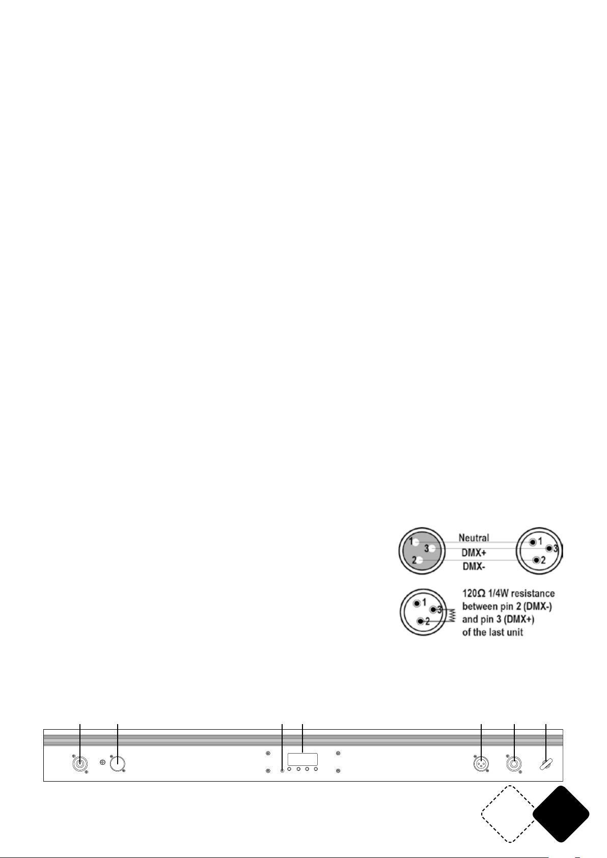
Connect an XLR cable to the male 3-pin XLR output of your controller and the other side to the female 3-pin XLR input of the light.You can chain multiple lights together through serial linking
The cable needed should be two core, screened cable with XLR input and output connectors.
DATA CABLING
To link xtures together you must use data cables. If you choose to create your own cable, please
use data-grade cables that can carry a high quality signal and are less prone to electromagnetic
interference.
CABLE CONNECTORS
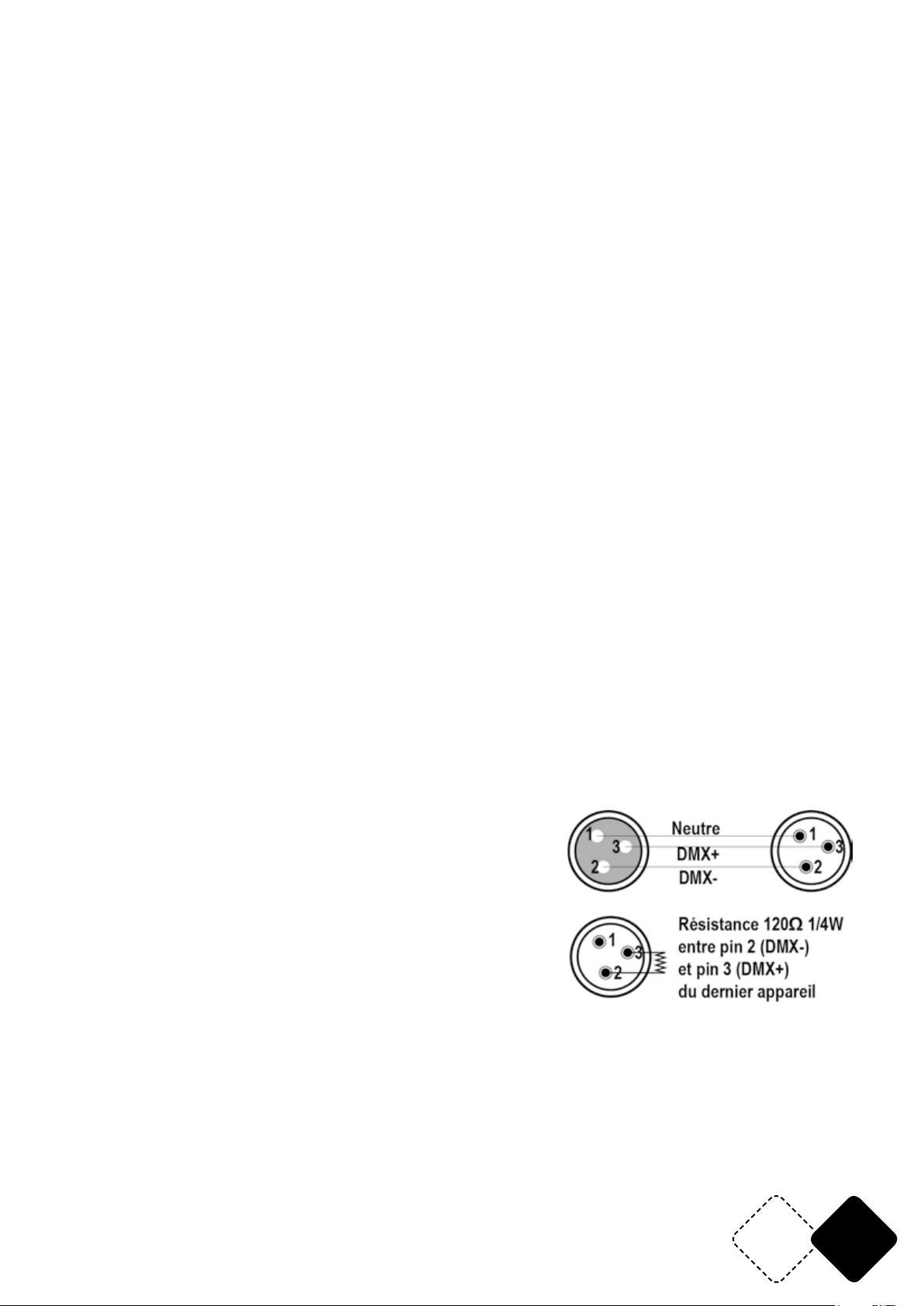
Cabling must have a male XLR connector on one end and a female
XLR connector on the other end.
Termination reduces signal errors. To avoid signal transmission
problems and interference, it is always advisable to connect a DMX
signal terminator.
CAUTION
Do not allow contact between the common and the xture’s chassis ground. Grounding the common can cause a ground loop, and
your xture may perform erratically. Test cables with an ohm meter to check correct polarity and
to make sure the pins are not grounded or shorted to the shield or each other.
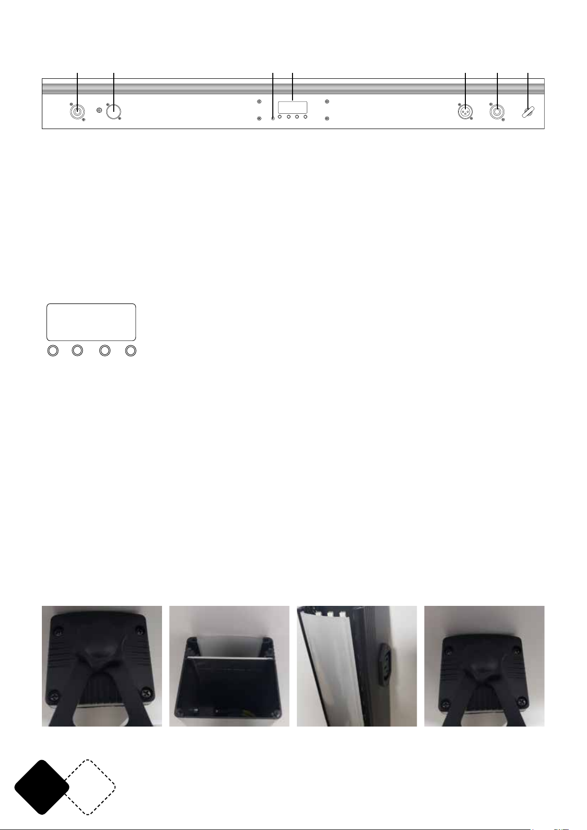
DESCRIPTION OF THE REAR PANEL
8.8.8.8.
MIC
UP
DOWN
MENU
POWER IN
DMX IN
ENTER
DMX OUT
www.afx-light.com
POWER OU T
SAFETY H OOK
EN3
Page 4
1. POWER IN: Connect the supplied mains lead to this connector and to an appropriate wall outlet.
2. DMX IN: Connect a DMX cable from the DMX output connector of a DMX controller to this DMX
input
3. Built-in microphone with adjustable sensitivity
4. LED display for the menu settings
5. DMX OUT: Connect this output to the DMX input connector of a slave unit
6. POWER OUT: Connect this power output to the POWER IN connector of a slave unit
7. Safety hook: For additional fastening of the unit to a truss system to avoid accidental falling of
the unit.
CONTROL PANEL
The control panel is the mechanism for conguring the settings. It has a small LCD screen and four
buttons, which are described below.
8.8.8.8.
DOW N
UP
MEN U ENT ER
BUTTON FUNCTION
<MENU>
Scrolls through the rst level of options, or exits from the current menu or function
<UP>
Navigates upward through the menu list or increases the numeric value when in a function
<DOWN>
Navigates downward through the menu list or decreases the numeric value when in a function
<ENTER>
Enables the currently displayed menu or sets the currently selected value in to the current function
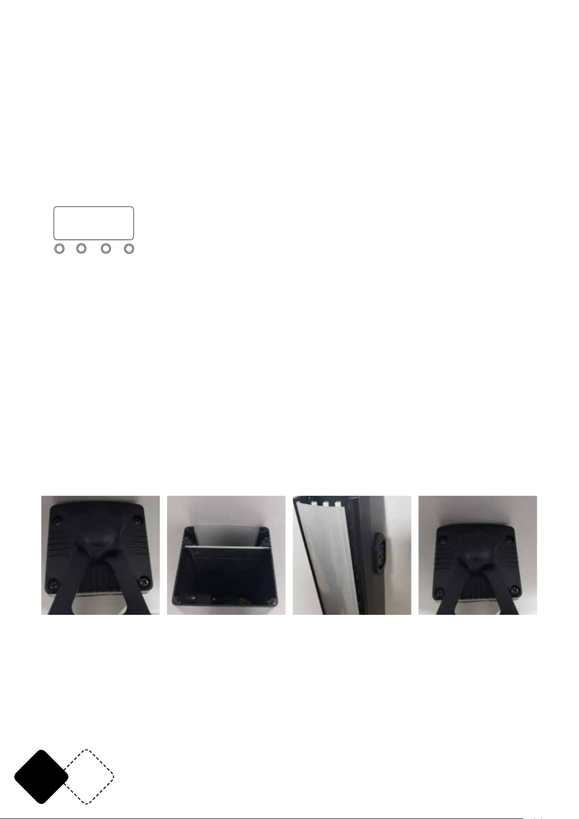
CHANGING THE FILTER
The unit is supplied with 2 lters: one clear lter and one Frost lter allowing to vary the effects.
The frost lter spreads the light at a wider angle e.g. to illuminate a wall.
To change the lter, proceed as follows:
Remove the 4 screws Remove the lter Put the new lter in place Fasten the 4 screws
EN 4
© Copyright LOTRONIC 2019
Page 5
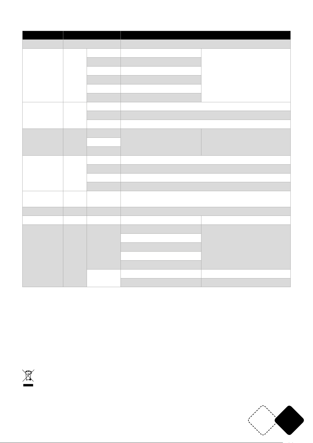
MENU STRUCTURE
Mode Programming Description
Auto mode Auto Auto mode
3 CH A001-A510
5 CH A001-A508
8 CH A001-A505
Each DMX Channel mode has
its individual address.
DMX mode Addr
24CH A001-A489
48CH A001-A465
Connect a controller and the
unit will enter into DMX mode.
53CH A001-A460
Sh 1-54 Program Show 1-54 (54 built-in effects)
Show Shou
Sp 1-10 Program Speed 1-10 (slow->fast) (Speed)
St 0-9 Program Flash 0-9 (slow->fast) (Strobe)
Sou1
Sound Mode Soud
Sou2
Sen1-9
Mic Sensitivity (Sound mode,
sensitivity adjustable)
Sou3
r000-255 Red (0-100%) Red adjustment
g000-255 Green (0-100%) Green adjustment
Edit color Colo
b000-255 Blue (0-100%) Blue adjustment
St 0 – St 9 LED Strobe (slow->fast) (Strobe)
Static colors StAt
CL00CL26
RGB static color (Static color)
Slave SLAV Slave Slave (Slave mode, Automatic identication slave unit)
Information Info ver VVxx Soft version
10s
Set backlight time of display
board,
10 S to light up
The factory default is 10 S
Product Set Set
dis
20s
30
60s
on
---> Set the direction to the right
dir
<--- Set the direction to the left
DMX Channel Tables see at the end of the manual
SPECIFICATIONS
Power supply .................................................................................................................... 110-240V~50/60Hz
Consumption ................................................................................................................................................60W
Total max. power at the POWER OUT output ...................................................................................... 1500W
LED .................................................................................................................. 8 x 28pcs SMD5050 RGB 3-in-1
Dimensions .................................................................................................................................. 101 x 6 x 6cm
Weight ......................................................................................................................................................... 1.6kg
IMPORTANT NOTE: Electric products must not be put into household waste. Please bring them to a recycling centre. Ask your local
authorities or your dealer about the way to proceed.
www.afx-light.com
EN5
Page 6
MANUEL D'UTILISATION
ATTENTION
DÉBALLAGE
Dès réception de l’appareil, ouvrez le carton et vériez que le contenu est complet et en bon état.
Sinon, prévenez immédiatement le transporteur et conservez l’emballage s’il montre des signes de
mauvais traitements. Conservez le carton et tous les matériaux d’emballage an de pouvoir transporter l’appareil en toute sécurité.
CONTENU DE L'EMBALLAGE
• 1 pc. BARLED200-FX
• 1 pc. mode d'emploi
• 1 pc. câble d'alimentation Powercon
• 2 pc. étriers
EXPLICATION DES SYMBOLES SUR L'APPAREIL
L’éclair dans le triangle attire l’attention sur un danger physique (due à une électrocution p.
ex.).
Le point d’exclamation dans le triangle indique un risque dans la manipulation ou l’utilisation
de l’appareil.
L'appareil est conforme à la norme CE
Uniquement pour utilisation à l'intérieur
0.5m
Distance minimale entre l'appareil et d'autres objets
NE PAS OUVRIR LE BOITIER
RISQUE DE CHOC ELECTRIQUE
Lire attentivement ce manuel avant la première mise en service.
CONSIGNES DE SECURITE
• Lisez attentivement ce manuel qui contient des informations importantes sur l’installation, l’utilisation et l’entretien de cet appareil.
• Conservez le manuel pour référence ultérieure. Si l’appareil change un jour de propriétaire, assurez-vous que le nouvel utilisateur est en possession du manuel.
• Assurez-vous que la tension secteur convient à cet appareil et qu’elle ne dépasse pas la tension
d’alimentation indiqué sur la plaque signalétique de l’appareil.
• Cet appareil fait partie de la classe I et doit être impérativement branché sur une prise secteur
avec terre.
• Uniquement pour utilisation à l'intérieur!
• An d’éviter tout risque d’incendie ou de choc électrique, ne pas exposer cet appareil à la pluie
ou à l’humidité. Assurez-vous qu’aucun objet inammable ne se trouve à proximité de l’appareil
pendant son fonctionnement.
• Installez l’appareil à un endroit bien ventilé à une distance minimum de 50cm de toute surface.
Assurez-vous que les fentes de ventilation ne sont pas bloquées.
• La distance minimale entre le luminaire et l’objet éclairé doit s’élever à 0,5m..
• Débranchez l’appareil du secteur avant toute manipulation ou entretien.
• La température ambiante ne doit pas dépasser 40°C. Ne pas faire fonctionner l’appareil à des
températures supérieures.
• En cas de dysfonctionnement, arrêtez immédiatement l’appareil. N’essayez jamais de réparer
l’appareil par vous-même. Une réparation mal faite peut entraîner des dommages et des dysfonctionnements. Contactez un service technique agréé. Utilisez uniquement des pièces détachées identiques aux pièces d’origine.
0.5m
FR 6
© Copyright LOTRONIC 2019
Page 7
• Si le cordon secteur de l’appareil est endommagé, il ne doit être remplacé que par le fabricant ou
son agent ou bien un technicien qualié an d’éviter tout risque d’électrocution..
• L’appareil doit être remplacé si celui-ci est endommagé ou déformé thermiquement.
• L’écran de protection des LEDs doit être remplacé s’il est visiblement endommagé au point de
nuire à son efcacité, par exemple en raison de ssures ou de rayures profondes.
• La source lumineuse de ce luminaire n'est pas remplaçable; lorsque la source lumineuse atteint
sa n de sa vie, le luminaire entier doit être remplacé.
• Assurez-vous que le cordon d’alimentation n’est jamais écrasé ni endommagé.
• Ne jamais débrancher l’appareil en tirant sur le cordon.
• Ne pas exposer vos yeux à la source lumineuse.
• Le luminaire ne doit servir qu’à des ns décoratives et ne convient pas comme éclairage domes-
tique normal.
DISPOSITIF DE COUPURE
Lorsqu’une che SECTEUR ou un coupleur sont utilisés pour déconnecter l’appareil du secteur, ce
dispositif doit rester facilement accessible à tout moment.
INSTALLATION
Fixez l’appareil au moyen des trous de vis sur l’étrier. Assurez-vous que l’appareil est solidement
xé pour éviter des vibrations et des mouvements pendant le fonctionnement. Veillez toujours à ce
que la structure qui accueille l’appareil, est sufsamment solide et capable de porter au moins 10
fois le poids propre de l’appareil.
L’appareil doit être xé par des professionnels à en endroit où il est hors de portée des personnes et
en dehors d’un chemin de passage.
Vous pouvez installer cet appareil dans n’importe quelle position pourvu qu’il y ait une ventilation
sufsante. Lors du choix d’un emplacement, tenez compte de la facilité d’accès à l’appareil pour
des travaux de maintenance et de nettoyage.
Ne jamais installer l’appareil à un endroit exposé à la pluie, l’humidité, aux changements de température importants et présentant une ventilation limitée.
CONNEXION DMX
Branchez le câble XLR sur la sortie mâle de votre contrôleur et l'autre extrémité sur l'entrée femelle
de l'appareil. Vous pouvez ainsi brancher plusieurs appareil en série.
CONNECTEURS DE CABLE
Le câble doit posséder une che XLR mâle d’un côté et XLR femelle de l’autre.
Une résistance de n de ligne réduit les erreurs de signal. Pour
éviter des problèmes de transmission des signaux, il est toujours conseillé de brancher une résistance de n de ligne DMX.
ATTENTION
Il ne doit y avoir aucun contact entre le commun et la masse
du châssis de l’appareil. La mise à la masse du commun peut
provoquer une boucle de masse et votre appareil fonctionne
d’une façon étrange. Testez les câbles à l’aide d’un ohm-mètre
an de vérier la polarité et de vous assurer que les broches
ne sont pas connectées à la masse ni court-circuitées sur le
blindage ou mutuellement.
www.afx-light.com
FR7
Page 8
DESCRIPTION DE L'ARRIERE
1 2 3 4 5 6 7
UP
DOW N
MEN U EN TER
8.8.8.8.
MIC
UP
DOWN
MENU
POWER IN
DMX IN
ENTER
DMX OUT
POWER OU T
SAFETY H OOK
1. POWER IN: Branchez le cordon secteur fourni sur cette prise et l'autre extrémité sur une prise
murale appropriée.
2. DMX IN: Branchez un câble DMX de la sortie d'un contrôleur DMX sur cette entrée DMX.
3. Microphone intégré avec réglage de senibilité
4. Afcheur à LED pour effectuer les réglages dans le menu
5. DMX OUT: Branchez cette sortie DMX sur l'entrée DMX d'un appareil esclave.
6. POWER OUT: Branchez cette sortie Powercon sur l'entrée Powercon d'un appareil esclave.
7. Crochet de sécurité: Permet une xation supplémentaire de l'appareil pour éviter tout accident
en cas de chute.
TABLEAU DE COMMANDE
Le panneau de commande est l'outil de conguration. Il s'agit d'un petit écran LCD avec quatre
boutons, décrits ci-dessous.
8.8.8.8.
FONCTION DU BOUTON:
<MENU>: Fait déler le premier niveau d'options ou quitter le menu ou la fonction en cours
<UP>: Navigue vers le haut dans la liste de menus ou augmente la valeur numérique dans une
fonction
<DOWN>: Navigue vers le bas dans la liste de menus ou diminue la valeur numérique dans une
fonction
<ENTER>: Active le menu actuellement afché ou dénit la valeur actuellement sélectionnée sur la
fonction actuelle
CHANGEMENT DU FILTRE
L'appareil est fourni avec 2 ltres: un ltre clair et un ltre Frost qui permettent de varier les effets.
Le ltre Frost diffuse la lumière à un angle plus large p.ex. pour éclairer un mur.
Pour changer le ltre, procédez de la manière suivante:
Retirez les 4 vis Retirez le ltre Mettez le nouveau ltre Fixez les 4 vis
en place
FR 8
© Copyright LOTRONIC 2019
Page 9
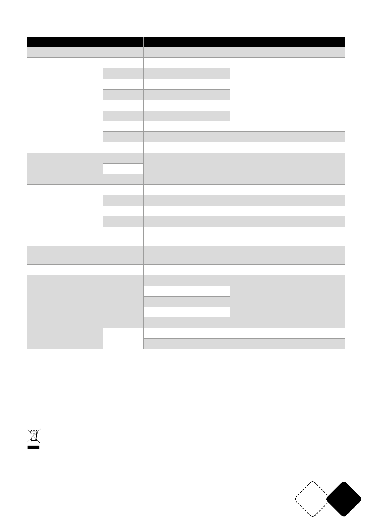
STRUCTURE DU MENU
Mode Programmation Description
Automatique Auto Auto mode
3 CH A001-A510
5 CH A001-A508
8 CH A001-A505
DMX Addr
24CH A001-A489
48CH A001-A465
Chaque mode DMX a son adresse
individuelle. Si vous branchez un
contrôleur, l'appareil commute
automatiquement en mode DMX.
53CH A001-A460
Sh 1-54 Programmes 1-54 (54 effets programmés)
Show Shou
Sp 1-10 Vitesse du programme 1-10 (lent -> rapide)
St 0-9 Stroboscope du programme 0-9 (lent -> rapide)
Sou1
Son Soud
Sou2
Sen1-9
Sensibilité du micro (ajustable en
mode Son)
Sou3
r000-255 Rouge (0-100%) Réglage des rouges
Edition des
couleurs
Colo
g000-255 Vert (0-100%) Réglage des verts
b000-255 Bleu (0-100%) Réglage des bleus
St 0 – St 9 Stroboscope à LED (lent -> rapide)
Couleurs
pures
StAt
Esclave SLAV Slave
CL00CL26
Couleurs pures RVB
Mode esclave (reconnaissance automatique de l'appareil
esclave)
Information Info ver VVxx Version du logiciel
10s
Réglage de la durée du rétroéclairage de l'écran,
10 S pour s'allumer
La valeur par défaut est 10 sec.
Paramétrage
de l'appareil
Set
dis
20s
30
60s
on
---> Sens de rotation vers la droite
dir
<--- Sens de rotation vers la gauche
CARACTÉRISTIQUES TECHNIQUES
Alimentation ..................................................................................................................... 110-240V~50/60Hz
Consommation .............................................................................................................................................60W
Puissance max. cumulée sur la sortie POWER OUT ............................................................................ 1500W
LED ................................................................................................................. 8 x 28pcs SMD5050 RGB 3-en-1
Dimensions .................................................................................................................................. 101 x 6 x 6cm
Poids ............................................................................................................................................................ 1,6kg
NOTE IMPORTANTE : Les produits électriques ne doivent pas être mis au rebut avec les ordures ménagères. Veuillez les faire recycler
là où il existe des centres pour cela. Consultez les autorités locales ou votre revendeur sur la façon de les recycler.
www.afx-light.com
FR9
Page 10
BEDIENUNGSANLEITUNG
VORSICHT
AUSPACKEN
Sofort nach Empfang vorsichtig den Karton auspacken und den Inhalt überprüfen. Alle Teile müssen
vollzählig und in einwandfreiem Zustand sein. Sofort die Transportrma benachrichtigen und das
Verpackungsmaterial aufbewahren, wenn Teile Transportschäden aufweisen. Verpackungsmaterial
auch für späteren Transport des Geräts aufbewahren.
VERPACKUNGSINHALT
• 1 x BARLED200-FX Lichteffektgerät
• 1 Powercon Netzkabel
• Bedienungsanleitung
• 2 Befstigungsbügel
• 1 klarer Filter
ZEICHENERKLÄRUNG
Der Blitz im Dreieck weist auf Gesundheitsrisiken hin (z.B. Stromschlag)
Das Ausrufezeichen im Dreieck weist auf besondere Gefahren im Umgang oder Betrieb des
Geräts hin.
Das Gerät entspricht der CE Norm
Nur für Innengebrauch
0.5m
Mindestabstand zwischen dem Gerät und anderen Gegenständen
NICHT DAS GEHÄUSE ÖFFNEN
STROMSCHLAGGEFAHR
Vor der ersten Inbetriebnahme des Geräts sorgfältig die Anleitung durchlesen.
SICHERHEITSHINWEISE
• Diese Anleitung sorgfältig vor der ersten Inbetriebnahme lesen. Sie enthält wichtige Informationen über Installation, Gebrauch und Instandhaltung des Geräts.
• Die Anleitung für spätere Bezugnahme aufbewahren und an den nächsten Bediener weitergeben.
• Stets die Netzspannung vor Anschluss des Geräts überprüfen Sie muss mit der auf der Rückseite
des Geräts angegebenen Spannung übereinstimmen und darf auf keinen Fall höher sein.
• Das Gerät gehört zur Schutzklasse 1 und darf nur an eine Steckdose mit Schutzkontakt
angeschlossen werden.
• Nur für Innengebrauch!
• Um Brand und Stromschlag zu vermeiden, das Gerät vor Regen und Feuchtigkeit schützen. Keine
brennbaren Materialien während des Betriebs in der Nähe des Geräts lassen.
• Das Gerät muss an einem gut belüfteten Ort und in mindestens 50cm Entfernung zur nächsten
Fläche angebracht werden.
• Darauf achten, dass die Belüftungsschlitze nicht blockiert oder verstopft sind.
• Immer erst das Gerät vom Netz trennen, bevor es gewartet oder die Sicherung ersetzt wird. Die
Sicherung nur durch eine identische ersetzen.
• Das Gerät mit einer Sicherheitskette befestigen.
• Die Raumtemperatur darf 40°C nicht überschreiten. Das Gerät niemals bei höheren Temperatu-
ren betreiben.
• Bei Betriebsstörungen das Gerät sofort ausschalten. Das Gerät niemals selbst reparieren. Reparaturen dürfen nur von einem Fachmann vorgenommen werden. Alle verwendeten Ersatzteile
müssen mit den Originalteilen identisch sein.
0.5m
DE 10
© Copyright LOTRONIC 2019
Page 11
• Das Gerät muss entsorgt werden, wenn es beschädigt oder thermisch verformt ist.
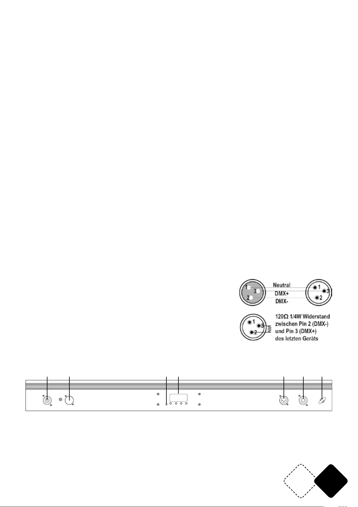
1 2 3 4 5 6 7
• Der LED-Schutzschirm muss ausgetauscht werden, wenn er sichtbar so stark beschädigt ist,
dass seine Wirksamkeit beeinträchtigt wird, beispielsweise durch Risse oder tiefe Kratzer.
• Die Lichtquelle dieser Leuchte ist nicht austauschbar. Wenn die Betriebsdauer der Lichtquelle
abgelaufen ist, muss die gesamte Leuchte ausgetauscht werden.
• Das Gerät nicht an ein Dimmerpack anschließen.
• Das Netzkabel niemals quetschen oder beschädigen.
• Beim Abziehen des Netzsteckers nur am Stecker ziehen, niemals am Kabel.
• Niemals direkt in die Lichtquelle blicken. Das kann bei empndlichen Personen zu epileptischen
Anfällen führen.
• Das Gerät ist nur für dekorative Zwecke und nicht als normale Haushaltsbeleuchtung geignet.
NETZTRENNUNGSVORRICHTUNGEN
a) Wenn das Gerät über den Netzstecker ausgeschaltet wird, muss die Steckdose jederzeit leicht
zugänglich bleiben
b) Wenn das Gerät über einen Schalter ausgeschaltet wird, muss dieser klar gekennzeichnet und
leicht zugänglich sein.
INSTALLATION
Das Gerät kann in jeder beliebigen Stellung montiert werden, solange für ausreichende Belüftung
gesorgt ist. Der Ventilator und die Belüftungsschlitze dürfen auf keinen Fall behindert werden. Bei
der Wahl des Anbringungsortes darauf achten, dass das Gerät leicht zugänglich für Wartungs- und
Reinigungsarbeiten bleibt. Das Gerät muss fest und sicher installiert werden, um Erschütterungen und Spielraum während der Bewegungen zu vermeiden. Die Montageäche muss stabil sein
und mindestens 10-mal das Gewicht des Geräts tragen können. Bei der Montage das Gerät immer
zusätzlich durch ein Sicherheitskabel absichern. Das Gerät darf nur von einem Fachmann installiert werden. Es muss an einer Stelle installiert werden, wo es für Menschen unzugänglich ist und
niemand unter dem Montagebereich stehen oder gehen kann.
DMX VERBINDUNG
Ein XLR Kabel mit 3-pol. XLR Stecker an den Ausgang des Steuergeräts und die 3-pol. XLR Buchse
an den DMX Eingang des Geräts anschliessen. Auf diese Weise können mehrere Geräte hintereinander in Serie geschlossen werden.
Die Kabel müssen abgeschirmt, 2-adrig sein und einen XLR Stecker auf der einen und eine XLR
Buchse auf der anderen Seite besitzen. S. nachstehende Abbildung:
Bei längeren Kabelwegen ist es empfehlenswert, einen
Endwiderstand zwischen Pin 2 und 3 zu löten, um Signalfehler zu
vermeiden.
Ein Endwiderstand von 120 Ohm 1/4W wird zwischen Pin 2 (DMX-)
und Pin 3 (DMX+) am letzten Gerät gelötet.
BESCHREIBUNG DER RÜCKSEITE
8.8.8.8.
MIC
UP
DOWN
MENU
POWER IN
DMX IN
ENTER
DMX OUT
POWER OU T
SAFETY H OOK
1. POWER IN: Schliessen Sie das mitgelieferte Powercon-Kabel an diesen Verbinder an und das andere Ende in eine geeignete Wandsteckdose.
2. DMX IN: Schliessen Sie ein DMX Kabel vom Ausgangsverbinder eines DMX-Steuerpults an diesen
DMX Eingangsverbinder an.
3. Eingebautes Mikrofon mit regelbarer Empndlichkeit
4. LED Display zeigt die Menü-Einstellungen an
www.afx-light.com
DE11
Page 12
5. DMX OUT: DMX Ausgang zum Anschluss an den DMX Eingang eines Slave-Geräts
6. POWER OUT: Powerdon Ausgang zum Anschluss an den Powercon Eingang eines Slave-Geräts
7. Sicherheitshaken: Für eine zusätzliche Befestigung des Geräts.
BEDIENFELD
Über das Bedienfeld werden die Einstellungen vorgenommen. Es besteht aus einem kleinen LCD-Display und 4 Tasten, die nachstehend beschrieben werden.
8.8.8.8.
DOW N
UP
MEN U ENT ER
TASTENFUNKTIONEN
<MENU>
Durchlaufen der ersten Ebene der Optionen, bzw. Verlassen des Menüs oder der Funktion.
<UP>
Läuft aufwärts durch die Menüliste bzw. erhöht die Zahl oder den Wert einer Funktion
<DOWN>
Läuft abwärts durch die Menüliste bzw. verringert die Zahl oder den Wert einer Funktion
<ENTER>
Aktiviert den angezeigten Menüpunkt bzw. bestätigt den gewählten Wert in der Funktion
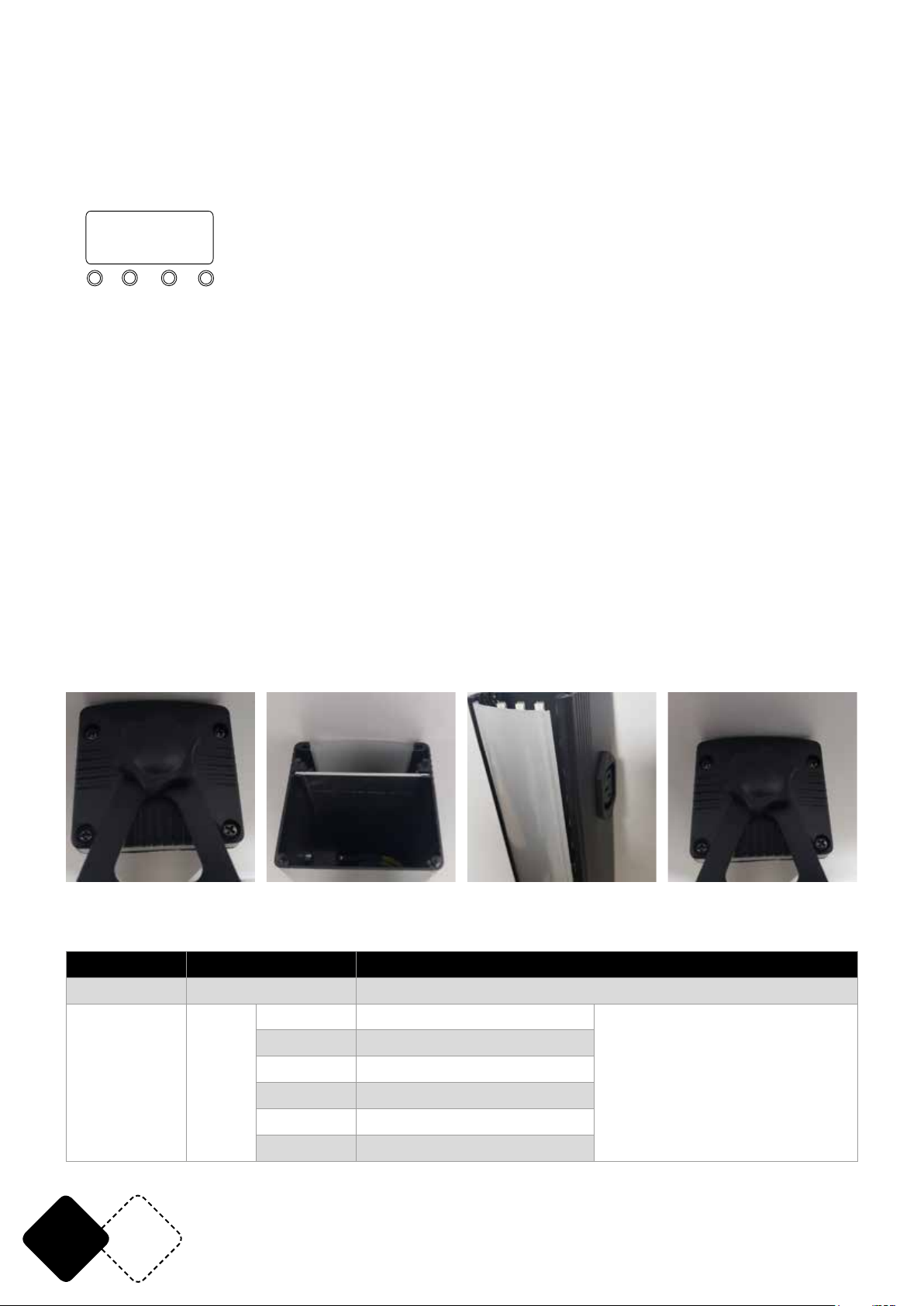
FILTERWECHSEL
Das Gerät wird mit 2 Filtern geliefert: einem durchsichtigen und einem Frost Filter, so dass verschiedene Effekte erzeugt werden können. Der Frost Filter verstreut das Licht weiter und eignet sich
z.B. zum Anstrahlen einer Wand.
Zum Filterwechsel wie folgt vorgehen:
4 Schrauben entfernen Filter entnehmen Neuen Filter einsetzen Schrauben festziehen
MENÜSTRUKTUR
Betriebsart Programmierung Beschreibung
Automatik Auto Automatikbetrieb
3 CH A001-A510
5 CH A001-A508
8 CH A001-A505
DMX Addr
24CH A001-A489
48CH A001-A465
53CH A001-A460
Jede DMX Betriebsart benötigt
ihre eigene Adresse. Wenn ein
DMX Steuerpult angeschlossen
wird, schaltet das Gerät automatisch auf DMX Betrieb um
DE 12
© Copyright LOTRONIC 2019
Page 13
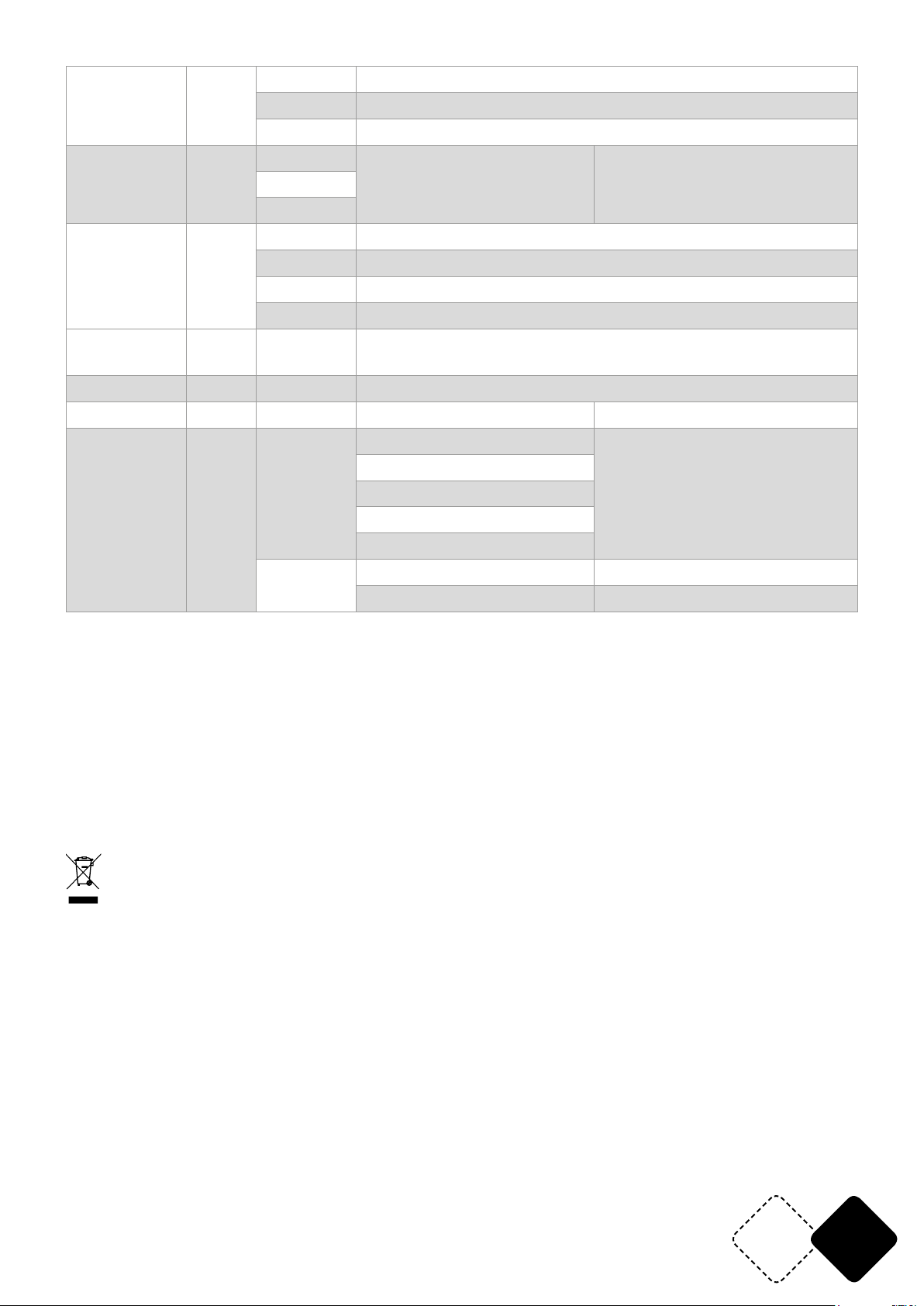
Sh 1-54 Programm 1-54 (54 eingebaute Effekte)
Show Shou
Sp 1-10 Programmgeschwindigkeit 1-10 (langsam -> schnell)
St 0-9 Programmstroboskop 0-9 (langsam -> schnell)
Klangakti-
vierung
Soud
Sou1
Sou2
Sou3
Sen1-9
Mikrofonempndlichkeit
(Klangaktivierter Betrieb,
einstellbare Empndlichkeit)
r000-255 Rot (0-100%) Roteinstellung
Farbe editie-
ren
Colo
g000-255 Green (0-100%) Grüneinstellung
b000-255 Blue (0-100%) Blaueinstellung
St 0 – St 9 LED Stroboskop (langsam -> schnell)
Reine Farben StAt
CL00CL26
RGB reine Farben (Static color)
Slave SLAV Slave Slave-Betrieb (automatische Erkennung des Slave-Geräts)
Information Info ver VVxx Softwareversion
10s
Einstellung der Hintergrundbeleuchtung,
10 Sek. Einschaltdauer
Ab Werk auf 10 Sek. eingestellt
Product Set Set
dis
20s
30
60s
on
---> Rechtsbewegung
dir
<--- Linksbewegung
Die DMX Kanaltabellen benden sich am Ende dieser Anleitung
TECHNISCHE DATEN
Versorgung ........................................................................................................................ 110-240V~50/60Hz
Verbrauch ......................................................................................................................................................60W
Max. Gesamtbelastung am POWER OUT Ausgang .............................................................................1500W
LED .................................................................................................................. 8 x 28 St. SMD5050 RGB 3-in-1
Abmessungen .............................................................................................................................. 101 x 6 x 6cm
Gewicht ........................................................................................................................................................ 1.6kg
WICHTIGER HINWEIS: Elektrogeräte gehören nicht in den Hausmüll. Sie müssen in speziellen Betrieben recycelt werden.
Bringen Sie sie zu einer speziellen Entsorgungsstelle für Elektrokleingeräte (Wertstoffhof)!
www.afx-light.com
DE13
Page 14
HANDLEIDING
UITPAKKEN
Onmiddellijk naar de aankoop van het toestel, verwijder voorzichtig de verpakking en wees zeker
dat het toestel in geode toestand is. Breng direct uw dealer op de hoogte en bewaar het verpakkingsmateriaal indien onderdelen of het karton door het transport beschadigd zijn. Bewaar het
karton en alle verpakkingsmaterialen. Indien het toestel moet gerepareerd worden is het belangrijk
het toestel in zijn originele verpakking te versturen.
VERPAKKINGSINHOUD
• 1 st. BEAM100-LED
• 1 st. handleiding
• 1 st. Powercon voedingskabel
• 1. st. lter
• 2 houders
VERKLARING VAN DE TEKENS
De driehoek met een bliksemschicht wordt gebruikt om aan te geven wanneer uw gezondheid
gevaar loopt (bijvoorbeeld door elektrocutie).
Een uitroepteken in een driehoek wijst op bijzondere risico's bij het hanteren of bedienen van
het apparaat.
Het apparaat voldoet aan de CE-normen
Alleen voor gebruik binnenshuis
0.5m
Minimale afstand tussen het apparaat en andere objecten
LET OP
NIET DE BEHUIZING OPENEN
GEVAAR VOOR ELECTRISCHE SCHOKKEN
Lees de handleiding aandachtig door. Ze bevat belangrijke informaties voor de installatie, gebruik en onderhoud van dit toestel.
VEILIGHEIDSINSTRUCTIES
• Bewaar deze handleiding.
• Wees zeker dat u het toestel op de juiste spanning aansluit en dat de lichtnetspanning niet hoger
dan de op de zijde van het toestel aangegeven spanning is.
• Alleen voor gebruik binnenshuis!
• Dit apparaat behoort tot beschermingsklasse I. Het moet dus verplicht worden geaard. Een be-
voegde persoon moet de elektrische aansluiting uitvoeren.
• Om vuur en elektrische schokken te verhinderen bescherm het toestel tegen regen en vochtigheid. Wees zeker dat geen ontvlambare materialen in de buurt van het toestel zijn tijdens de
werking.
• Plaats het toestel in een ruimte met voldoende ventilatie en in tenminste 50cm afstand van oppervlakken.
• Wees zeker dat de ventilatie openingen niet geblokkeerd zijn.
• Verwijder het stopcontact alvorens u het toestel onderhoud of de zekering vervangt. Gebruik
alleen een zekering met dezelfde specicaties.
• Gebruik het toestel niet in ruimtes met een temperatuur boven 40°C.
• In geval van een ernstig probleem stopt het toestel direct. Verzoek nooit het toestel zelfs te re-
pareren. Alle reparaties moeten van een ervarene technicus doorgevoerd worden. Gebruik alleen
onderdelen met dezelfde specicaties.
• Het apparaat moet worden vervangen als het beschadigd of vervormd is.
• Het LED-beschermingsglas moet worden vervangen als het zichtbaar is beschadigd om de effec-
NL 14
© Copyright LOTRONIC 2019
Page 15
tiviteit ervan te beïnvloeden, bijvoorbeeld door barsten of diepe krassen.
• De lichtbronnen van de lichteffecten zijn niet vervangbaar. Als een lichtbron defect is, moet het
lichteffect worden weggegooid.
• Sluit het toestel niet op een dimmer pack aan.
• Nooit het netsnoer beschadigen of platdrukken.
• Nooit aan de kabel trekken.
• Nooit in de lichtbron kijken. Gevoelige personen kunnen een epileptische shock ondergaan
(vooral bedoeld voor epileptica)
• Het product is uitsluitend bedoeld voor decoratieve doeleinden en niet geschikt als verlichting
van de huiskamer.
ONTKOPPELING VAN HET NET
a) Indien het toestel via het stopcontact wordt uitgeschakeld, moet de contactdoos altijd gemakkelijk bereikbaar zijn
b) Indien het toestel via een schakelaar wordt uitgeschakeld, moet deze duidelijk gemarkeerd en
gemakkelijk bereikbaar zijn.
INSTALLATIE
De unit kan in iedere positie geïnstalleerd worden mits voor voldoende koeling gezorgd is.
Het is belangrijk nooit de ventilator of de koelingsopeningen te verstoppen. Bij de keuze van d ’ins-
tallatie plaats denk eraan dat de plaats gemakkelijk bereikbaar is voor onderhoud en reinigingsdoeleinden.
Gebruik altijd veiligheidskabels.
Bescherm het toestel tegen regen, vochtigheid en extreme temperatuurveranderingen. Kies een
plaats met voldoende ventilatie.
Bevestig het toestel via de schroef gaten op de houder. Wees zeker dat het toestel vast geïnstalleerd
is om trillingen en afglijden tijdens de werking te vermijden. Wees zeker dat de truss waaraan u het
toestel bevestigd, stabiel is en 10 keer het gewicht van het toestel kan dragen. Tijdens de montage,
gebruik altijd een veiligheidskabel dat 12 keer het gewicht kan dragen.
Het toestel moet van een vakman op een plaats monteert worden waar het buiten het bereik van
mensen is en niemand onder kan staan.
DATA AANSLUITING
Gebruik een twee-aderige afgeschermde data kabels met XLR-ingangs- en uitgangsaansluitingen.
Indien U uw eigen kabel bouwen wilt gebruik hoogwaardige kabels die het signaal goed overdragen
en niet gevoelig zijn voor elektromagnetische interferenties.
KABELCONNECTOREN
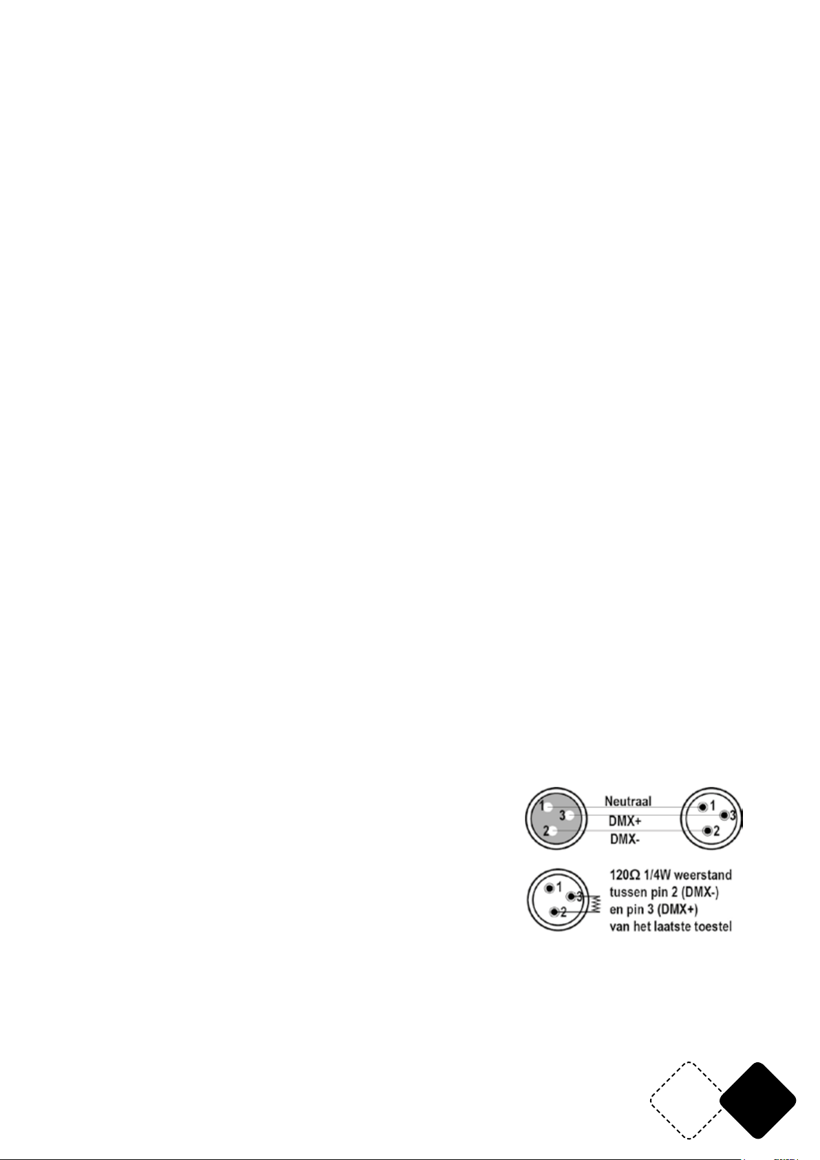
De kabel moet een XLR stekker op één eind en een XLR contra op het andere eind hebben.
DMX CONNECTOR CONFIGURATIE
De eindweerstand vermindert signaalfouten. Om transmissie
problemen en storingen te voorkomen is het aanbevolen een
DMX signaal eindweerstand aan te sluiten.
LET OP
Geen contact maken tussen common en chassis massa. Indien de common op de massa aangesloten is kan een aardlus
ontstaan en het toestel werkt willekeurig. Controleer de kabels
d.m.v. een ohmmeter om de polariteit te controleren en te waarborgen dat de pins niet op aarde
aangesloten of met elkaar kortgesloten zijn.
www.afx-light.com
NL15
Page 16
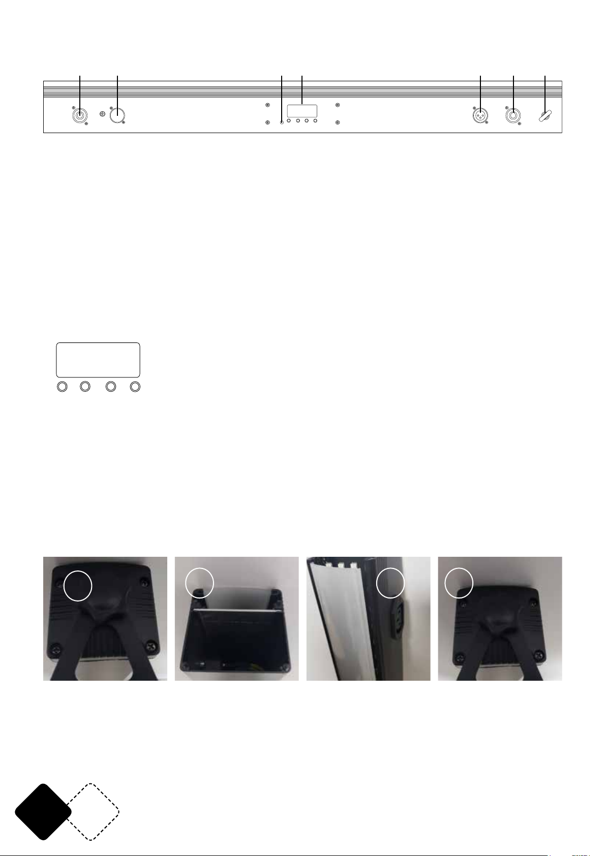
OMSCHRIJVING VAN HET ACHTERPANEEL
1 2 3 4 5 6 7
8.8.8.8.
MIC
UP
DOWN
MENU
POWER IN
DMX IN
ENTER
DMX OUT
POWER OU T
SAFETY H OOK
1. POWER IN: sluit het meegeleverde netsnoer aan op deze connector en op een geschikt stopcontact.
2. DMX IN: verbind een DMX-kabel van de DMX-uitgang van een DMX-controller met deze DMX-in-
gang
3. Ingebouwde microfoon met instelbare gevoeligheid
4. LED-display voor de menu-instellingen
5. DMX OUT: verbind deze uitgang met de DMX-ingangsconnector van een slave-eenheid
6. POWER OUT: verbind deze stroomuitgang met de POWER IN-connector van een slave-eenheid
7. Veiligheidshaak: voor extra bevestiging van de unit aan een truss-systeem om te voorkomen dat de unit per ongeluk valt.
CONTROLE PANEEL
De LED display heeft 4 toetsen: MENU / UP / DOWN / ENTER
Druk op MENU om de submenu's te openen. Beweeg met de toetsen OMHOOG en OMLAAG. Bevestig
uw keuze met ENTER.
8.8.8.8.
DOW N
UP
MEN U ENT ER
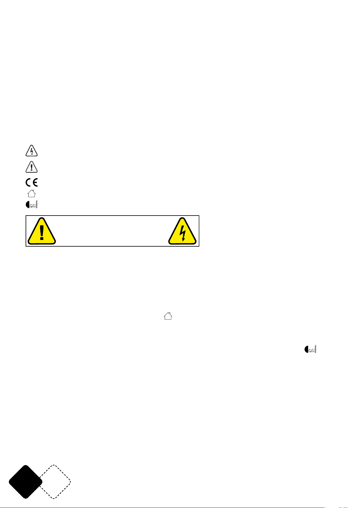
HET FILTER VERVANGEN
De unit wordt geleverd met 2 lters: een helder lter en een Frost-lter waarmee de effecten kunnen worden gevarieerd. Het frost lter verspreidt het licht onder een bredere hoek, b.v. om een
muur te verlichten.
Ga als volgt te werk om het lter te vervangen:
1. Verwijder de 4 schroeven
2. Verwijder het lter
3. Plaats het nieuwe lter op zijn plaats
4. Bevestig de 4 schroeven
1
2 3 4
NL 16
© Copyright LOTRONIC 2019
Page 17
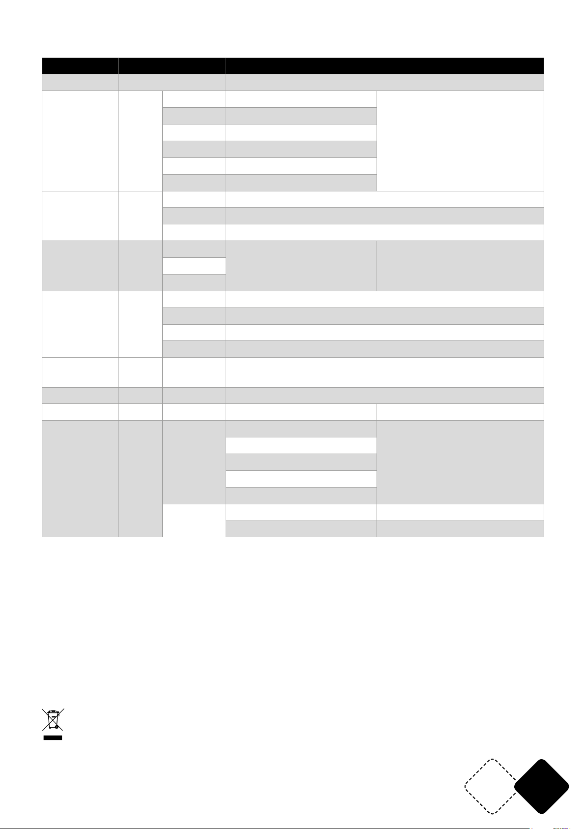
MENU STRUCTUUR
Mode Programmering Omschrijving
Auto mode Auto Automatische modus
3 CH A001-A510
5 CH A001-A508
8 CH A001-A505
DMX mode Addr
24CH A001-A489
48CH A001-A465
Elke DMX-modus vereist een
eigen adres. Wanneer een
DMX-controller is aangesloten,
schakelt het apparaat automatisch over naar DMX-werking
53CH A001-A460
Sh 1-54 Program Show 1-54 (54 ingebouwde effecten)
Show Shou
Sp 1-10 Program snelheid 1-10 (langzaam -> snel)
St 0-9 Program Flash 0-9 (langzaam -> snel) (Strobe)
Sound Mode Soud
Sou1
Sou2
Sou3
Sen1-9
Microfoon gevoeligheid
(geluidsmodus, instelbare
gevoeligheid)
r000-255 Rood (0-100%) Rood instellen
g000-255 Groen (0-100%) Groen instellen
Edit color Colo
b000-255 Blauw (0-100%) Blauw instellen
St 0 – St 9 LED Strobe (langzaam -> snel) (Strobe)
Static colors StAt
CL00CL26
RGB pure kleuren (Static color)
Slave SLAV Slave Slave (Slave modus, automatische herkenning van de slave)
Information Info ver VVxx Soft versie
10s
Instellen van de duur van de
achtergrondverlichting,
10 S verlichting
Werksinstelling is 10 S
Product Set Set
dis
20s
30
60s
on
---> In rechter richting
dir
<--- In linker richting
DMX kanalen zie aan het eind van de handleiding
SPECIFICATIES
Voeding .............................................................................................................................. 110-240V~50/60Hz
Opgenomen vermogen ................................................................................................................................60W
Totale max. belasting op de POWER OUT uitgang .............................................................................. 1500W
LED ................................................................................................................... 8 x 28 st. SMD5050 RGB 3-in-1
Afmetingen .................................................................................................................................. 101 x 6 x 6cm
Gewicht ........................................................................................................................................................ 1.6kg
BELANGRIJK: De elektrische producten mogen niet naast het huisvuil geplaatst worden. Gelieve deze te laten recycleren daar waar er
centra’s hiervoor voorzien is. Raadpleeg de plaatselijke autoriteiten of uw verkoper ivm de manier van recycleren
www.afx-light.com
NL17
Page 18
MANUAL DE INSTRUCCIONES
PREPARATIVOS
A la recepción del equipo, abra el embalaje y compruebe que todas las piezas están en buen estado
y que está todo el equipo completo. Conserve el embalaje, para poder trasladar el equipo con toda
seguridad.
DESEMBALAJE
• 1 Efecto de ilumnación
• 1 Cable de corriente Powercon
• 1 Manal de instrucciones
• 2 Soportes
• 1 ltro transparente
EXPLICACION DE LOS SIMBOLOS DEL EQUIPO
El rayo dentro de un triángulo avisa al usuario de un daño físico (Riesgo de electrocución, por
ejemplo).
El punto de exclamación dentro del triángulo indica un riesgo en la manipulación o instalación
del equipo.
El equipo es conforme a la norma CE
Únicamente para su uso en interiores
0.5m
Distancia mínima entre el equipo y otros objetos
ATENCION
NO ABRIR LA CARCASA
PELIGRO DE ELECTROCUCION
INSTRUCCIONES DE SEGURIDAD
Lea atentamente este manual que contiene informaciones importantes de la instalación, uso y
mantenimiento de este equipo.
• Conserve el manual para consultas futuras. Si el equipo cambia de propietario algún día asegúrese de que recibe el manual.
• Asegúrese de que la tensión del enchufe, se corresponde con las necesidades del equipo y no supera el Voltaje requerido por el equipo e indicado en la placa indicadora del mismo.
• Únicamente para ser usado en interiores!
• Para evitar cualquier riesgo de incendio o descarga eléctrica, no exponga el equipo a la lluvia o
la humedad. Asegúrese de que ningún objeto inamable se encuentra cerca del equipo durante
el funcionamiento del mismo.
• La distancia mínima entre el proyector y el objeto a iluminar debe ser superior a 0,5m.
• Desenchufe el equipo de la corriente antes de cualquier manipulación o mantenimiento.
• La temperatura ambiente no debe pasar de 40°C. No haga funcionar el equipo a temperaturas
superiores.
• En caso de malfuncionamiento, pare inmediatamente el equipo. No intente jamás reparar usted
mismo el equipo. Una reparación mal efectuada, puede provocar daños y malfuncionamientos.
Contacte con un servicio autorizado. Haga que utilicen únicamente recambios originales.
• El aparato debe reemplazarse si está dañado o deformado térmicamente.
• La pantalla de protección LED debe reemplazarse si está visiblemente dañada hasta el punto de
afectar su efectividad, por ejemplo debido a grietas o rasguños profundos.
• La fuente de luz de esta luminaria no es reemplazable. Cuando la fuente de luz llega al nal de
su vida útil, se debe reemplazar toda la luminaria. Asegúrese de que le cable de corriente nunca
esté dañado o pellizcado.
• Jamás desenchufe el equipo tirando del cable, hágalo desde la propia clavija y con cuidado.
• No exponga los ojos a la fuente luminosa. En ciertas personas sensibles, la fuerte luminosidad
0.5m
.
ES 18
© Copyright LOTRONIC 2019
Page 19
puede provocar una crisis de epilepsia
1 2 3 4 5 6 7
• La luminaria no se ha de usar con nes decorativos y no es adecuada como iluminación domestica normal.
DISPOSITIVO DE CORTE
Cuándo el cable de corriente o el interruptor del equipo, sean utilizados como método de desconexión, este dispositivo debe permanecer fácilmente accesible;
INSTALACION
Fije el equipo por medio de los agujeros de tornillo en el soporte. Asegúrese de que su equipo está
sólidamente jado para evitar vibraciones y movimientos durante el funcionamiento. Compruebe
siempre que la estructura que soporta el equipo sea sucientemente sólida y capaz de soportar al
menos 10 veces el peso del equipo.
El equipo debe ser jado por profesionales en un lugar dónde no está al alcance de las personas y
no pase nadie por debajo de el o encima de un camino de personas.
CONEXION DMX
CONEXIONADO DE MAS EFECTOS
Necesitará un cable de datos en serie para poder hacer funcionar más efectos por medio de una
controladora DMX512 o para hacer funcionar 2 o más efectos en modo Maestro/Esclavo. El número combinado de canales requerido por el conjunto de equipos en un cable de datos en serie dene
el número de equipos que el cable de datos puede soportar.
Importante: Los equipos deben estar conectados en serie en una sola línea. La distancia máxima
recomendada es de 100m. El número máximo de equipos conectados en una red de datos es de 16.
CÂBLEADO
Para conectar los equipos juntos, debe de utilizar cables de transmisión de datos. Usted puede
comprar los cables DMX certicados directamente a su vendedor/distribuidor o construir sus propios cables. Si usted quiere construirlos usted mismo, utilice los cables de datos de alta calidad que
estarán más protegidos de las interferencias electromagnéticas.
CONECTORES DE CABLE
El cable debe de tener una conexión XLR macho en uno de los lados y una conexión XLR Hembra al
otro lado.
CONFIGURACIÓN DE LOS CONECTORES DMX
Una resistencia de nal de línea reduce los errores de señal. Para evitar
problemas de transmisión de señales, es aconsejable de conectar una
resistencia de n de línea DMX.
ATENCION
No debe de haber ningún contacto entre el común y la masa del chasis
del equipo. La conexión de la masa del común puede provocar un bucle de masa y su equipo funcionará de manera extraña. Compruebe los cbles con la ayuda de un óhmetro para conrmar la
polaridad y asegurarse que las tomas no están conectadas a masa ni cortocircuitadas con el blindaje o mutuamente.
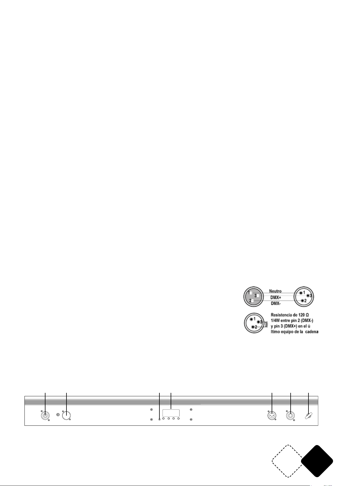
DESCRIPCION DE LA PARTE POSTERIOR
8.8.8.8.
MIC
UP
DOWN
MENU
POWER IN
DMX IN
ENTER
DMX OUT
POWER OU T
1. POWER IN: Conecte el cable de corriente incluido en esta toma y la otra extremidad en un enchufe adecuado.
www.afx-light.com
SAFETY H OOK
ES19
Page 20
2. DMX IN: Conecte un cable DMX de la salida de un controlador DMX en esta entrada DMX.
3. Micrófono con ajuste de sensibilidad
4. Display de LED para efectuar los ajustes de menú
5. DMX OUT: Conecte esta salida DMX en la entrada DMX de un equipo esclavo.
6. POWER OUT: Conecte esta salida Powercon en la entrada Powercon de un equipo esclavo.
7. Gancho de seguridad: Permite una jación suplementaria del equipo, para evitar cualquier accidente en caso de caída.
DISPLAY DE LED
El display cuenta con 4 botones: MENU / UP / DOWN / ENTER
Encienda la unidad, presione MENÚ para ingresar a los MENÚS SECUNDARIOS, presione UP / DOWN
para elegir un submenú, luego conrme su elección con ENTRAR.
8.8.8.8.
DO WN
ME NU EN TER
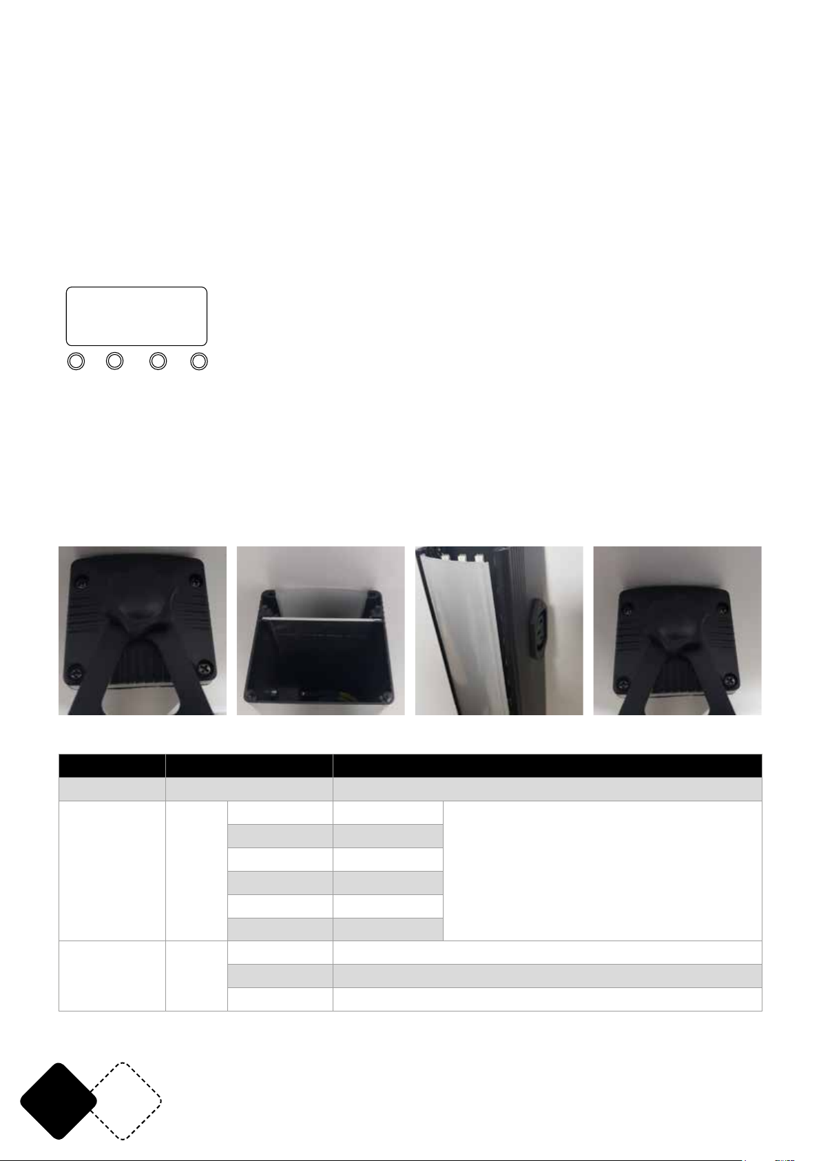
CAMBIO DE FILTRO
El equipo está dotado con 2 ltros: un ltro transparente y otro Frost que permite variar los efectos. El ltro Frost difumina la luz en un ángulo más amplio, para por ejemplo la iluminación de una
pared.
Para cambiar el ltro, proceda de la siguiente manera:
Retire los 4 tornillos Retire el ltro Coloque de nuevo el ltro Fije los 4 tornillos
en su sitio
UP
ESTRUCTURA DEL MENÚ
Modo Programación Descripción
Automático Auto Auto modo
3 CH A001-A510
5 CH A001-A508
DMX Addr
Show Shou
8 CH A001-A505
24CH A001-A489
48CH A001-A465
53CH A001-A460
Sh 1-54 Programas 1-54 (54 efectos programados)
Sp 1-10 Velocidad del programa 1-10 (lento -> rápido)
St 0-9 Estroboscopio de programa 0-9 (lento -> rápido)
ES 20
Cada modo de canal cuenta con una
dirección individual. Si usted conecta un
controlador, el equipo conmuta automáticamente a modo DMX.
© Copyright LOTRONIC 2019
Page 21
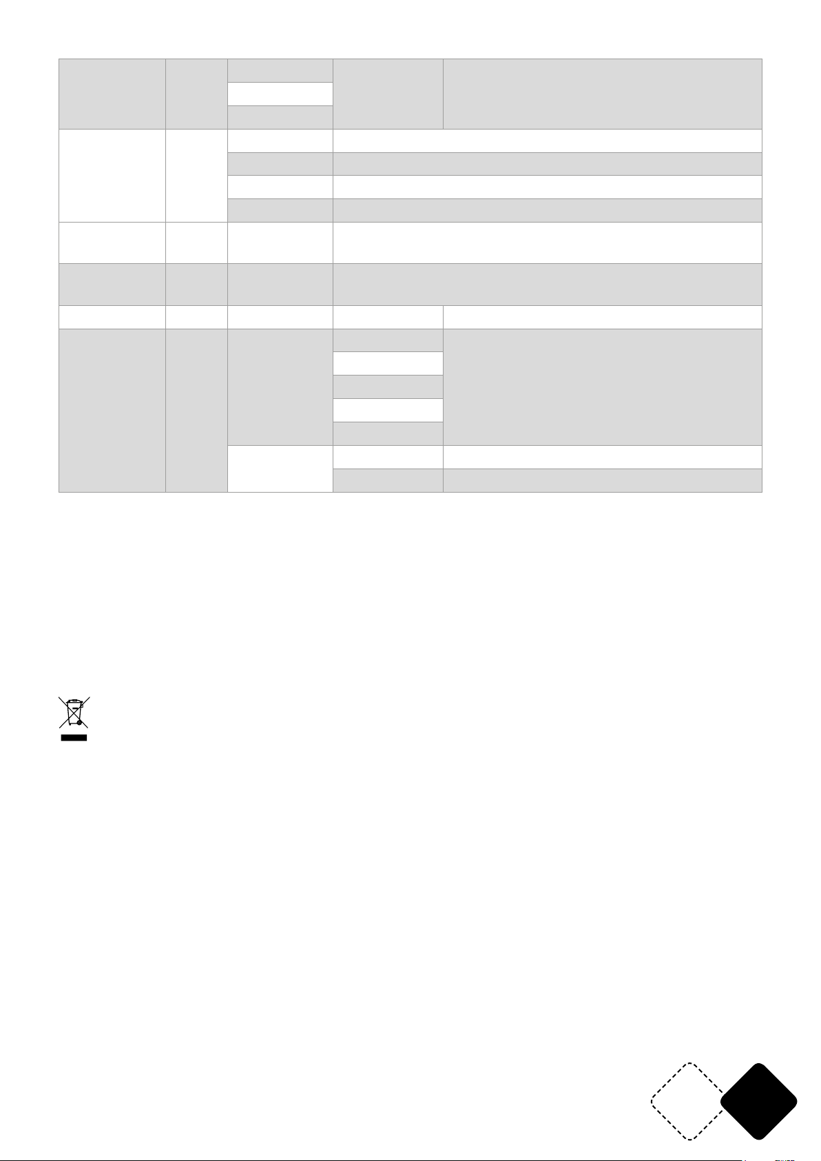
Sou1
Son Soud
Sou2
Sen1-9
Sensibilidad del micro ajustable (ajustable
en modo sonido)
Sou3
r000-255 Rojo (0-100%) Ajuste de los Rojos
Edición de
colores
Colo
g000-255 Verde (0-100%) Ajuste de los Verdes
b000-255 Azul (0-100%) Ajuste de los Azules
St 0 – St 9 Estroboscopio de LED (lento -> rápido)
Colores
puros
Esclavo SLAV Slave
StAt CL00-CL26 Colores puros RGB
Modo esclavo ( reconocimiento automático del equipo
esclavo)
Información Info ver VVxx Versión del software
10s
Ajuste de la duración de la retroiluminación de la pantalla
10 S para encenderse
El valor por defecto es de 10 sec.
Ajuste del
equipo
Set
dis
20s
30
60s
on
---> Sentido de rotación hacía la derecha
dir
<--- Sentido de rotación hacía la izquierda
CARACTERISTICAS TÉCNICAS
Alimentación .................................................................................................................... 110-240V~50/60Hz
Consumo .......................................................................................................................................................60W
Total max. carga en la salida POWER OUT ......................................................................................... 1500W
LED ................................................................................................................. 8 x 28pcs SMD5050 RGB 3-en-1
Dimensiones ................................................................................................................................ 101 x 6 x 6cm
Peso ............................................................................................................................................................. 1,6kg
ELIMINACIÓN DEL PRODUCTO
Este símbolo indica que este producto no debe desecharse en la basura doméstica en los países de la Comunidad Europea. Para
proteger el medio ambiente y / o la salud humana de la eliminación no controlada, debe reciclarse de manera responsable para apoyar
la reutilización sostenible de los recursos. Para reciclar el equipo usado, llévelo a un centro de recolección de electrodomésticos o comuníquese con el distribuidor donde adquirió el producto. Asegurarán el reciclaje ecológico del producto.
www.afx-light.com
ES21
Page 22
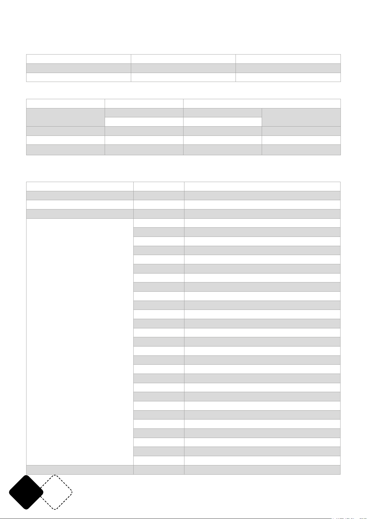
DMX Channel Tables:
DMX MODE1:3 CH
CH1 0-255 ALL RED (0-100%)
CH2 0-255 ALL GREEN (0-100%)
CH3 0-255 ALL BLUE (0-100%)
DMX MODE2:5 CH
CH1 0-255 Dimmer (Master dimmer)
CH2
CH3 0-255 ALL RED (0-100%)
CH4 0-255 ALL GREEN (0-100%)
CH5 0-255 ALL BLUE (0-100%)
DMX MODE3:8 CH
CH1 0-255 Dimmer (Master dimmer )
CH2 0-255 ALL RED (0-100%)
CH3 0-255 ALL GREEN (0-100%)
CH4 0-255 ALL BLUE (0-100%)
CH5 (When CH6 value <10, this DMX
Channels is valid)
0-9 No Function
10-255 Slow->Fast
0-9 No Function (CH2-Ch4 eective)
10-13 Static color(CH7 Choice)
14-17 Built-in eects 1
18-21 Built-in eects 2
22-25 Built-in eects 3
26-29 Built-in eects 4
30-33 Built-in eects 5
34-37 Built-in eects 6
38-41 Built-in eects 7
42-45 Built-in eects 8
46-49 Built-in eects 9
50-53 Built-in eects 10
54-57 Built-in eects 11
58-61 Built-in eects 12
62-65 Built-in eects 13
66-69 Built-in eects 14
70-73 Built-in eects 15
74-77 Built-in eects 16
78-81 Built-in eects 17
82-85 Built-in eects 18
86-89 Built-in eects19
90-93 Built-in eects20
94-97 Built-in eects 21
98-101 Built-in eects 22
102-105 Built-in eects 23
106-109 Built-in eects 24
110-113 Built-in eects 25
114-117 Built-in eects 26
Strobe (Strobe)
EN 22
© Copyright LOTRONIC 2019
Page 23
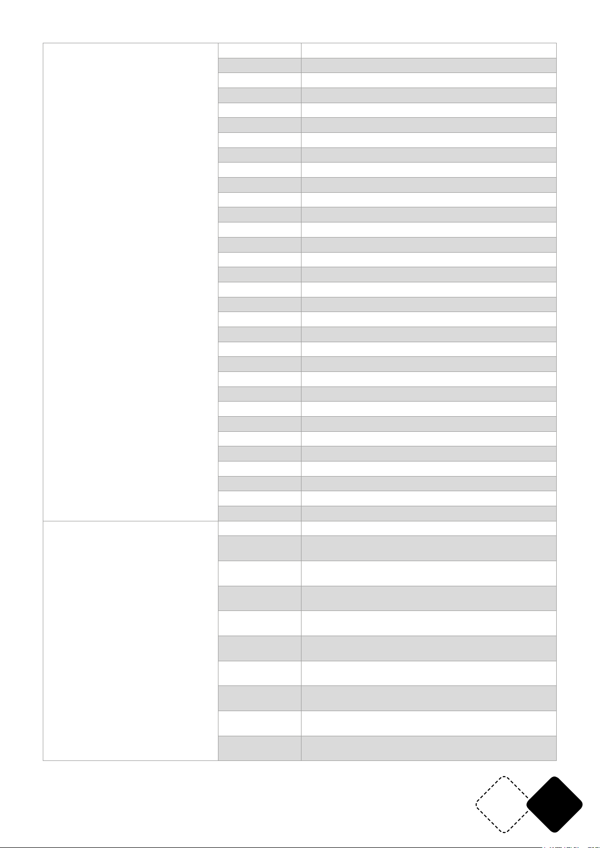
CH5 (When CH6 value <10, this DMX
Channels is valid)
CH6 (Prior to CH5)
118-121 Built-in eects 27
122-125 Built-in eects 28
126-129 Built-in eects 29
130-133 Built-in eects 30
134-137 Built-in eects 31
138-141 Built-in eects 32
142-145 Built-in eects 33
146-149 Built-in eects 34
150-153 Built-in eects 35
154-157 Built-in eects 36
158-161 Built-in eects 37
162-165 Built-in eects 38
166-169 Built-in eects 39
170-173 Built-in eects 40
174-177 Built-in eects 41
178-181 Built-in eects42
182-185 Built-in eects 43
186-189 Built-in eects 44
190-193 Built-in eects 45
194-197 Built-in eects 46
198-201 Built-in eects 47
202-205 Built-in eects 48
206-209 Built-in eects 49
210-213 Built-in eects 50
214-217 Built-in eects 51
218-221 Built-in eects 52
222-225 Built-in eects 53
226-229 Built-in eects 54
230-233 Auto Mode (Run built in eects 1-54)
234-237 DMX Sound mode1
238-241 DMX Sound mode2
242-255 DMX Sound mode3
0-9 No Function (CH5 valid )
10-15
16-21
22-27
28-33
34-39
40-45
46-51
52-57
58-63
Segment 1 LED light up, CH2, CH3, CH4 control color
(CH7>100, the other LED segments are o)
Segment 2 LED light up, CH2, CH3, CH4 control color
(CH7>100, the other LED segments are o)
Segment 3 LED light up, CH2, CH3, CH4 control color
(CH7>100, the other LED segments are o)
Segment 4 LED light up, CH2, CH3, CH4 control color
(CH7>100, the other LED segments are o)
Segment 5 LED light up, CH2, CH3, CH4 control color
(CH7>100, the other LED segments are o)
Segment 6 LED light up, CH2, CH3, CH4 control color
(CH7>100, the other LED segments are o)
Segment 7 LED light up, CH2, CH3, CH4 control color
(CH7>100, the other LED segments are o)
Segment 8 LED light up, CH2, CH3, CH4 control color
(CH7>100, the other LED segments are o)
Segment 9 LED light up, CH2, CH3, CH4 control color
(CH7>100, the other LED segments are o)
www.afx-light.com
EN23
Page 24
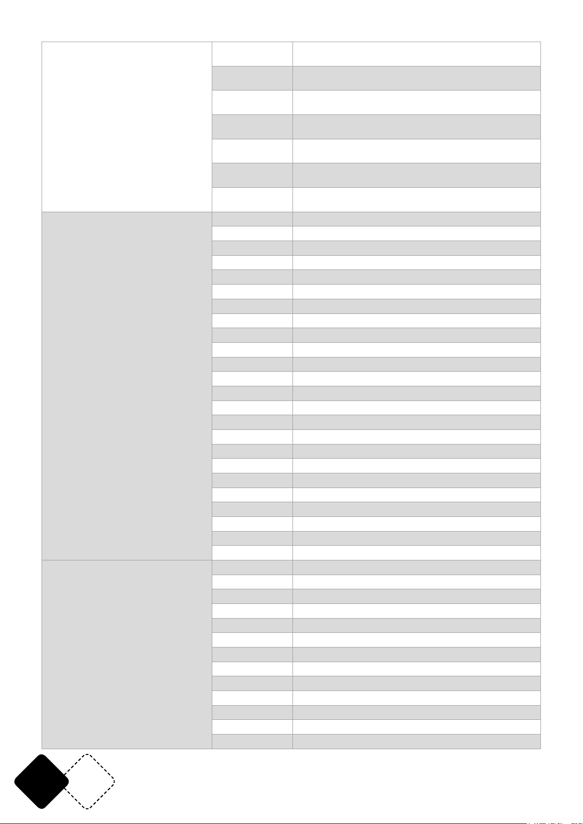
CH6
CH7
64-69
70-75
76-81
82-87
88-93
94-99
100-105
106-111 Pattern Eect 1(CH2, CH3, CH4 Control pattern color)
112-117 Pattern Eect 2(CH2, CH3, CH4 Control pattern color)
118-123 Pattern Eect 3(CH2, CH3, CH4 Control pattern color)
124-129 Pattern Eect 4(CH2, CH3, CH4 Control pattern color)
130-135 Pattern Eect 5(CH2, CH3, CH4 Control pattern color)
136-141 Pattern Eect 6(CH2, CH3, CH4 Control pattern color)
142-147 Pattern Eect 7(CH2, CH3, CH4 Control pattern color)
148-153 Pattern Eect 8(CH2, CH3, CH4 Control pattern color)
154-159 Pattern Eect 9(CH2, CH3, CH4 Control pattern color)
160-165 Pattern Eect 10(CH2, CH3, CH4 Control pattern color)
166-171 Pattern Eect 11(CH2, CH3, CH4 Control pattern color)
172-177 Pattern Eect 12(CH2, CH3, CH4 Control pattern color)
178-183 Pattern Eect 13(CH2, CH3, CH4 Control pattern color)
184-189 Pattern Eect 14(CH2, CH3, CH4 Control pattern color)
190-195 Pattern Eect 15(CH2, CH3, CH4 Control pattern color)
196-201 Pattern Eect 16(CH2, CH3, CH4 Control pattern color)
202-207 Pattern Eect 17(CH2, CH3, CH4 Control pattern color)
208-213 Pattern Eect 18(CH2, CH3, CH4 Control pattern color)
214-219 Pattern Eect 19(CH2, CH3, CH4 Control pattern color)
220-225 Pattern Eect 20(CH2, CH3, CH4 Control pattern color)
226-231 Pattern Eect 21(CH2, CH3, CH4 Control pattern color)
232-237 Pattern Eect 22(CH2, CH3, CH4 Control pattern color)
238-243 Pattern Eect 23(CH2, CH3, CH4 Control pattern color)
244-255 Pattern Eect 24(CH2, CH3, CH4 Control pattern color)
0-255 DMX Program Speed (Slow->fast)
0-9 No function
10-19 Static color 1 (10<=CH5 Value <=13)
20-29 Static color 2 (10<=CH5 Value <=13)
30-39 Static color 3 (10<=CH5 Value <=13)
40-49 Static color 4 (10<=CH5 Value <=13)
50-59 Static color 5 (10<=CH5 Value <=13)
60-69 Static color 6 (10<=CH5 Value <=13)
70-79 Static color 7 (10<=CH5 Value <=13)
80-89 Static color 8 (10<=CH5 Value <=13)
90-99 Static color 9 (10<=CH5 Value <=13)
100-109 Static color 10 (10<=CH5 Value <=13)
110-119 Static color 11 (10<=CH5 Value <=13)
Segment 10 LED light up, CH2, CH3, CH4 control color
(CH7>100, the other LED segments are o)
Segment 11 LED light up, CH2, CH3, CH4 control color
(CH7>100, the other LED segments are o)
Segment 12 LED light up, CH2, CH3, CH4 control color
(CH7>100, the other LED segments are o)
Segment 13 LED light up, CH2, CH3, CH4 control color
(CH7>100, the other LED segments are o)
Segment 14 LED light up, CH2, CH3, CH4 control color
(CH7>100, the other LED segments are o)
Segment 15 LED light up, CH2, CH3, CH4 control color
(CH7>100, the other LED segments are o)
Segment 16 LED light up, CH2, CH3, CH4 control color
(CH7>100, the other LED segments are o)
EN 24
© Copyright LOTRONIC 2019
Page 25
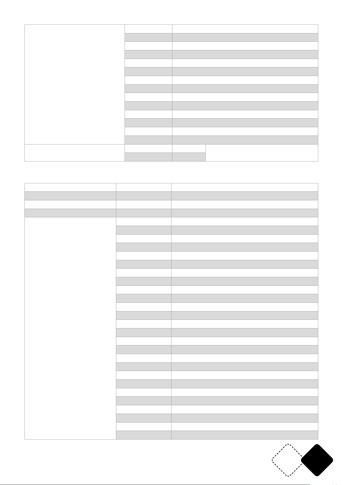
120-129 Static color 12 (10<=CH5 Value <=13)
130-139 Static color 13 (10<=CH5 Value <=13)
140-149 Static color 14 (10<=CH5 Value <=13)
150-159 Static color 15 (10<=CH5 Value <=13)
160-169 Static color 16 (10<=CH5 Value <=13)
170-179 Static color 17 (10<=CH5 Value <=13)
CH7
CH8
180-189 Static color 18 (10<=CH5 Value <=13)
190-199 Static color 19 (10<=CH5 Value <=13)
200-209 Static color 20 (10<=CH5 Value <=13)
210-219 Static color 21 (10<=CH5 Value <=13)
220-229 Static color 22 (10<=CH5 Value <=13)
230-239 Static color 23 (10<=CH5 Value <=13)
240-249 Static color 24 (10<=CH5 Value <=13)
250-255 Static color 25 (10<=CH5 Value <=13)
0-9 No Function Strobe (Strobe)
10-255 Slow->Fast
DMX MODE4:24CH
CH1 0-255 Dimmer (Master dimmer)
CH2 0-255 ALL RED (0-100%)
CH3 0-255 ALL GREEN (0-100%)
CH4 0-255 ALL BLUE (0-100%)
0-9 No Function (CH2-Ch4,CH9-CH24 Valid )
10-13 Static color (CH7 )
14-17 Built-in eects 1
18-21 Built-in eects 2
22-25 Built-in eects 3
26-29 Built-in eects 4
30-33 Built-in eects 5
34-37 Built-in eects 6
38-41 Built-in eects 7
42-45 Built-in eects 8
46-49 Built-in eects 9
50-53 Built-in eects 10
CH5 (When CH6 value <10,This dmx
channels is valid )
54-57 Built-in eects 11
58-61 Built-in eects 12
62-65 Built-in eects 13
66-69 Built-in eects 14
70-73 Built-in eects 15
74-77 Built-in eects 16
78-81 Built-in eects 17
82-85 Built-in eects 18
86-89 Built-in eects 19
90-93 Built-in eects 20
94-97 Built-in eects 21
98-101 Built-in eects 22
102-105 Built-in eects 23
106-109 Built-in eects 24
www.afx-light.com
EN25
Page 26
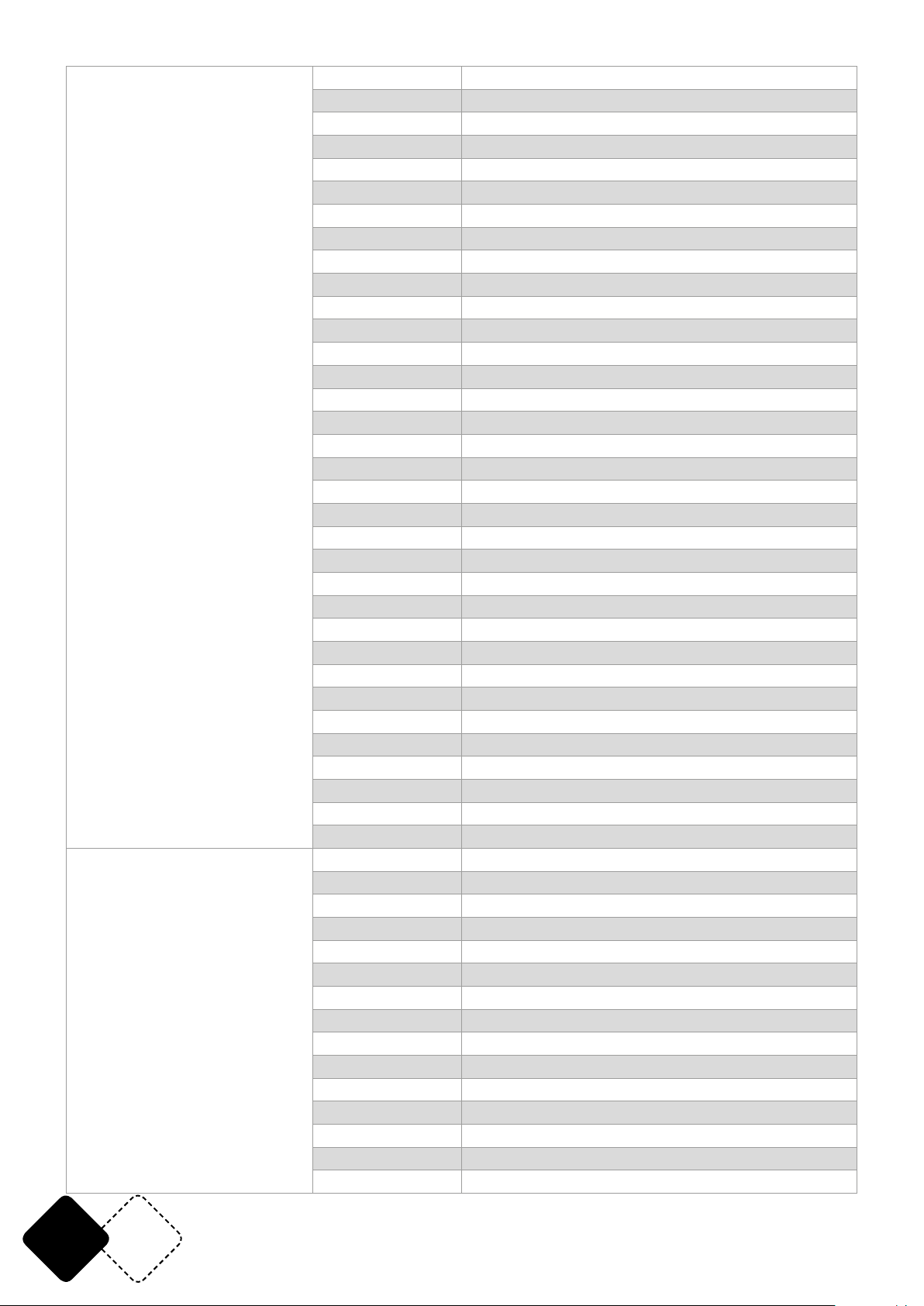
CH5 (When CH6 value <10, this dmx
channel is valid )
CH6 (Prior to CH5)
110-113 Built-in eects 25
114-117 Built-in eects 26
118-121 Built-in eects 27
122-125 Built-in eects 28
126-129 Built-in eects 29
130-133 Built-in eects 30
134-137 Built-in eects 31
138-141 Built-in eects 32
142-145 Built-in eects 33
146-149 Built-in eects 34
150-153 Built-in eects 35
154-157 Built-in eects 36
158-161 Built-in eects 37
162-165 Built-in eects 38
166-169 Built-in eects 39
170-173 Built-in eects 40
174-177 Built-in eects 41
178-181 Built-in eects 42
182-185 Built-in eects 43
186-189 Built-in eects 44
190-193 Built-in eects 45
194-197 Built-in eects 46
198-201 Built-in eects 47
202-205 Built-in eects 48
206-209 Built-in eects 49
210-213 Built-in eects 50
214-217 Built-in eects 51
218-221 Built-in eects 52
222-225 Built-in eects 53
226-229 Built-in eects 54
230-233 Auto Mode(Run built in eects 1-54)
234-237 DMX Sound mode1
238-241 DMX Sound mode2
242-255 DMX Sound mode3
0-9 No Function(CH5 Valid)
10-19 Pattern Eects 1 (CH2, CH3, CH4 Control pattern color )
20-29 Pattern Eects 2 (CH2, CH3, CH4 Control pattern color)
30-39 Pattern Eects 3 (CH2, CH3, CH4 Control pattern color)
40-49 Pattern Eects 4 (CH2, CH3, CH4 Control pattern color)
50-59 Pattern Eects 5 (CH2, CH3, CH4 Control pattern color)
60-69 Pattern Eects 6 (CH2, CH3, CH4 Control pattern color)
70-79 Pattern Eects 7 (CH2, CH3, CH4 Control pattern color)
80-89 Pattern Eects 8 (CH2, CH3, CH4 Control pattern color)
90-99 Pattern Eects 9 (CH2, CH3, CH4 Control pattern color)
100-109 Pattern Eects 10 (CH2, CH3, CH4 Control pattern color)
110-119 Pattern Eects 11 (CH2, CH3, CH4 Control pattern color)
120-129 Pattern Eects 12 (CH2, CH3, CH4 Control pattern color)
130-139 Pattern Eects 13 (CH2, CH3, CH4 Control pattern color)
140-149 Pattern Eects 14 (CH2, CH3, CH4 Control pattern color)
EN 26
© Copyright LOTRONIC 2019
Page 27
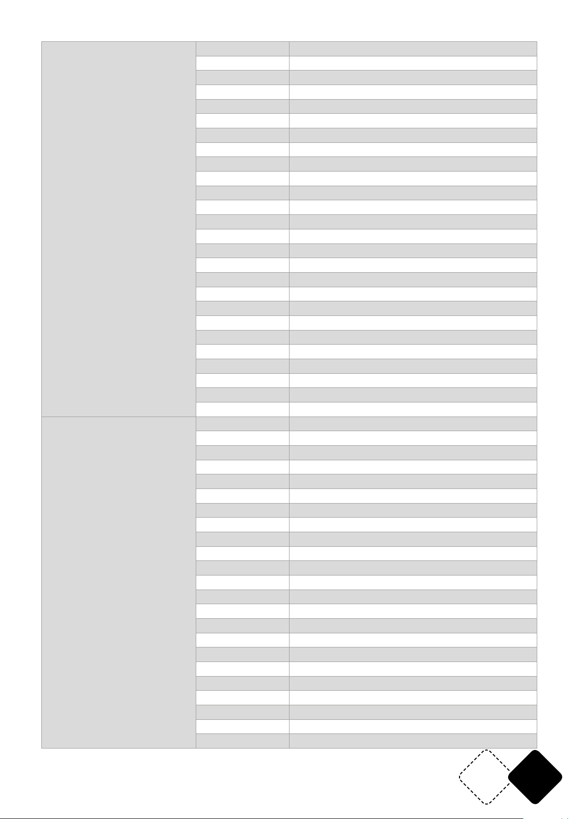
CH6 (Prior to CH5)
CH7
150-159 Pattern Eects 15 (CH2, CH3, CH4 Control pattern color)
160-169 Pattern Eects 16 (CH2, CH3, CH4 Control pattern color)
170-179 Pattern Eects 17 (CH2, CH3, CH4 Control pattern color)
180-189 Pattern Eects 18 (CH2, CH3, CH4 Control pattern color)
190-199 Pattern Eects 19 (CH2, CH3, CH4 Control pattern color)
200-209 Pattern Eects 20 (CH2, CH3, CH4 Control pattern color)
210-219 Pattern Eects 21 (CH2, CH3, CH4 Control pattern color)
220-229 Pattern Eects 22 (CH2, CH3, CH4 Control pattern color)
230-239 Pattern Eects 23 (CH2, CH3, CH4 Control pattern color)
240-255 Pattern Eects 24 (CH2, CH3, CH4 Control pattern color)
154-159 Pattern Eects 9 (CH2, CH3, CH4 Control pattern color)
160-165 Pattern Eects 10 (CH2, CH3, CH4 Control pattern color)
166-171 Pattern Eects 11 (CH2, CH3, CH4 Control pattern color)
172-177 Pattern Eects 12 (CH2, CH3, CH4 Control pattern color)
178-183 Pattern Eects 13 (CH2, CH3, CH4 Control pattern color)
184-189 Pattern Eects 14 (CH2, CH3, CH4 Control pattern color)
190-195 Pattern Eects 15 (CH2, CH3, CH4 Control pattern color)
196-201 Pattern Eects 16 (CH2, CH3, CH4 Control pattern color)
202-207 Pattern Eects 17 (CH2, CH3, CH4 Control pattern color)
208-213 Pattern Eects 18 (CH2, CH3, CH4 Control pattern color)
214-219 Pattern Eects 19 (CH2, CH3, CH4 Control pattern color)
220-225 Pattern Eects 20 (CH2, CH3, CH4 Control pattern color)
226-231 Pattern Eects 21 (CH2, CH3, CH4 Control pattern color)
232-237 Pattern Eects 22 (CH2, CH3, CH4 Control pattern color)
238-243 Pattern Eects 23 (CH2, CH3, CH4 Control pattern color)
244-255 Pattern Eects 24 (CH2, CH3, CH4 Control pattern color)
0-255 DMX Program Speed(Slow->fast)
0-9 No function
10-19 Static color 1 (10<=CH5 Value <=13)
20-29 Static color 2 (10<=CH5 Value<=13)
30-39 Static color 3 (10<=CH5 Value<=13)
40-49 Static color 4 (10<=CH5 Value<=13)
50-59 Static color 5 (10<=CH5 Value<=13)
60-69 Static color 6 (10<=CH5 Value<=13)
70-79 Static color 7 (10<=CH5 Value<=13)
80-89 Static color 8 (10<=CH5 Value<=13)
90-99 Static color 9 (10<=CH5 Value<=13)
100-109 Static color 10 (10<=CH5 Value<=13)
110-119 Static color 11 (10<=CH5 Value<=13)
120-129 Static color 12 (10<=CH5 Value<=13)
130-139 Static color 13 (10<=CH5 Value<=13)
140-149 Static color 14 (10<=CH5 Value<=13)
150-159 Static color 15 (10<=CH5 Value<=13)
160-169 Static color 16 (10<=CH5 Value<=13)
170-179 Static color 17 (10<=CH5 Value<=13)
180-189 Static color 18 (10<=CH5 Value<=13)
190-199 Static color 19 (10<=CH5 Value<=13)
200-209 Static color 20 (10<=CH5 Value<=13)
210-219 Static color 21 (10<=CH5 Value<=13)
www.afx-light.com
EN27
Page 28
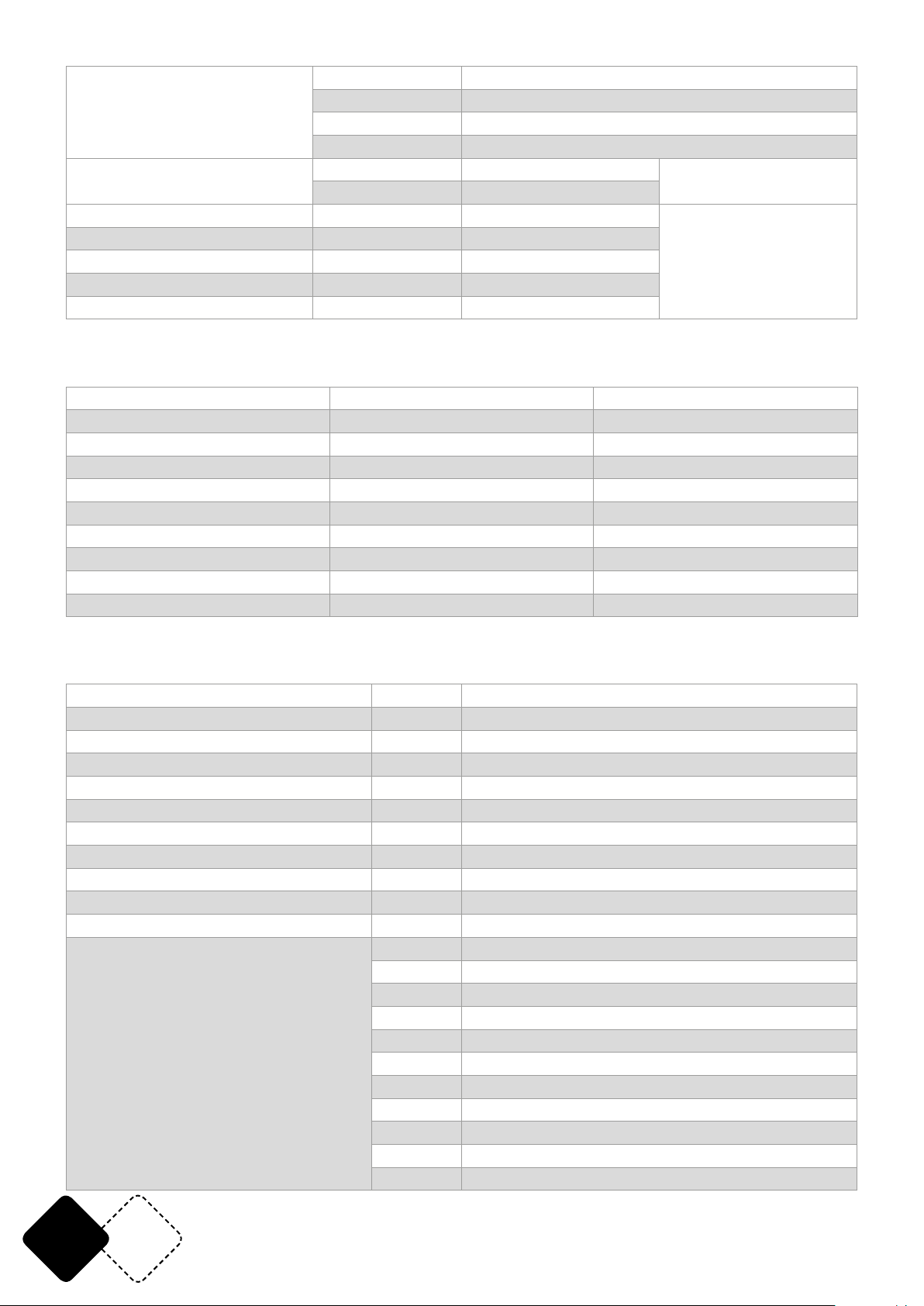
220-229 Static color 22 (10<=CH5 Value<=13)
230-239 Static color 23 (10<=CH5 Value<=13)
240-249 Static color 24 (10<=CH5 Value<=13)
250-255 Static color 25 (10<=CH5 Value<=13)
CH8
CH9 0-255 Segment 1 LED dimmer
CH9 0-255 Segment 2 LED dimmer
... ... ...
CH23 0-255 Segment 15 LED dimmer
CH24 0-255 Segment 16 LED dimmer
0-9 No Function
10-255 Slow->Fast
Strobe (Strobe)
When CH6<10 &
CH5<10,This dmx control
verse 1 LED brightness,
CH2~CH3 control color
DMX MODE5: 48CH
CH1 0-255 RED1 (0-100%)
CH2 0-255 GREEN1 (0-100%)
CH3 0-255 BLUE1 (0-100%)
CH4 0-255 RED2 (0-100%)
CH5 0-255 GREEN2 (0-100%)
CH6 0-255 BLUE2 (0-100%)
--- --- ---
CH46 0-255 RED16 (0-100%)
CH47 0-255 GREEN16 (0-100%)
CH48 0-255 BLUE16 (0-100%)
DMX MODE6: 53CH
CH1 0-255 Dimmer(Master Dimmer )
CH2 0-255 RED1 (0-100%)
CH3 0-255 GREEN1 (0-100%)
CH4 0-255 BLUE1 (0-100%)
CH5 0-255 RED2 (0-100%)
CH6 0-255 GREEN2 (0-100%)
CH7 0-255 BLUE2 (0-100%)
, , , , , , , , ,
CH47 0-255 RED16 (0-100%)
CH48 0-255 GREEN16 (0-100%)
CH49 0-255 BLUE16 (0-100%)
0-9 No Function (CH2-Ch49 Valid)
10-13 Static color(CH52 Choose)
14-17 Built-in eects 1
18-21 Built-in eects2
CH50 (when CH51 value <10, this DMX channel is valid)
22-25 Built-in eects 3
26-29 Built-in eects 4
30-33 Built-in eects 5
34-37 Built-in eects 6
38-41 Built-in eects 7
42-45 Built-in eects 8
46-49 Built-in eects 9
EN 28
© Copyright LOTRONIC 2019
Page 29
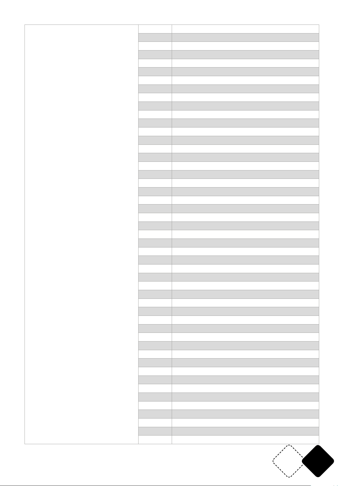
CH50 (when CH51 value <10, this DMX channel is valid)
50-53 Built-in eects 10
54-57 Built-in eects 11
58-61 Built-in eects 12
62-65 Built-in eects 13
66-69 Built-in eects 14
70-73 Built-in eects 15
74-77 Built-in eects 16
78-81 Built-in eects 17
82-85 Built-in eects 18
86-89 Built-in eects 19
90-93 Built-in eects 20
94-97 Built-in eects 21
98-101 Built-in eects 22
102-105 Built-in eects 23
106-109 Built-in eects 24
110-113 Built-in eects 25
114-117 Built-in eects 26
118-121 Built-in eects 27
122-125 Built-in eects 28
126-129 Built-in eects 29
130-133 Built-in eects 30
134-137 Built-in eects 31
138-141 Built-in eects 32
142-145 Built-in eects 33
146-149 Built-in eects 34
150-153 Built-in eects 35
154-157 Built-in eects 36
158-161 Built-in eects 37
162-165 Built-in eects 38
166-169 Built-in eects 39
170-173 Built-in eects 40
174-177 Built-in eects 41
178-181 Built-in eects 42
182-185 Built-in eects 43
186-189 Built-in eects 44
190-193 Built-in eects 45
194-197 Built-in eects 46
198-201 Built-in eects 47
202-205 Built-in eects 48
206-209 Built-in eects 49
210-213 Built-in eects 50
214-217 Built-in eects 51
218-221 Built-in eects 52
222-225 Built-in eects 53
226-229 Built-in eects 54
230-233 Auto Mode(Run Built-in eects 1-54)
234-237 DMX Sound mode1
238-241 DMX Sound mode2
242-255 DMX Sound mode3
www.afx-light.com
EN29
Page 30
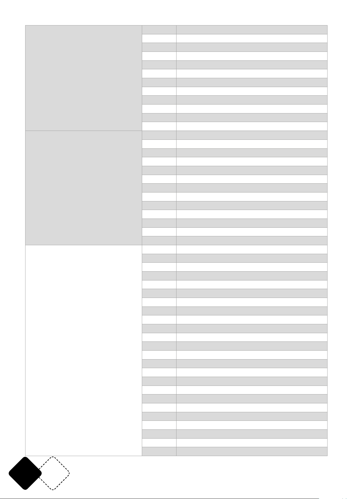
CH51 (Prior to CH50)
CH51 (Prior to CH50)
CH52
0-9 No Function (CH50 Valid)
10-19 Pattern eects 1 (CH2, CH3, CH4 Control pattern color)
20-29 Pattern eects 2 (CH2, CH3, CH4Control pattern color)
30-39 Pattern eects 3 (CH2, CH3, CH4 Control pattern color)
40-49 Pattern eects 4 (CH2, CH3, CH4 Control pattern color)
50-59 Pattern eects 5 (CH2, CH3, CH4 Control pattern color)
60-69 Pattern eects 6 (CH2, CH3, CH4 Control pattern color)
70-79 Pattern eects 7 (CH2, CH3, CH4 Control pattern color)
80-89 Pattern eects 8 (CH2, CH3, CH4 Control pattern color)
90-99 Pattern eects 9 (CH2, CH3, CH4 Control pattern color)
100-109 Pattern eects 10 (CH2, CH3, CH4 Control pattern color)
110-119 Pattern eects 11 (CH2, CH3, CH4 Control pattern color)
120-129 Pattern eects 12 (CH2, CH3, CH4 Control pattern color)
130-139 Pattern eects 13 (CH2, CH3, CH4 Control pattern color)
140-149 Pattern eects 14 (CH2, CH3, CH4 Control pattern color)
150-159 Pattern eects 15 (CH2, CH3, CH4 Control pattern color)
160-169 Pattern eects 16 (CH2, CH3, CH4 Control pattern color)
170-179 Pattern eects 17 (CH2, CH3, CH4 Control pattern color)
180-189 Pattern eects 18 (CH2, CH3, CH4 Control pattern color)
190-199 Pattern eects 19 (CH2, CH3, CH4 Control pattern color)
200-209 Pattern eects 20 (CH2, CH3, CH4 Control pattern color)
210-219 Pattern eects 21 (CH2, CH3, CH4 Control pattern color)
220-229 Pattern eects 22 (CH2, CH3, CH4 Control pattern color)
230-239 Pattern eects 23 (CH2, CH3, CH4 Control pattern color)
240-255 Pattern eects 24 (CH2, CH3, CH4 Control pattern color)
0-255 DMX Program Speed (Slow->fast)
0-9 No Function
10-19 Static color 1 (10<=CH50 Value<=13)
20-29 Static color 2 (10<=CH50 Value<=13)
30-39 Static color 3 (10<=CH50 Value<=13)
40-49 Static color 4 (10<=CH50 Value<=13)
50-59 Static color 5 (10<=CH50 Value<=13)
60-69 Static color 6 (10<=CH50 Value<=13)
70-79 Static color 7 (10<=CH50 Value<=13)
80-89 Static color 8 (10<=CH50 Value<=13)
90-99 Static color 9 (10<=CH50 Value<=13)
100-109 Static color 10 (10<=CH50 Value<=13)
110-119 Static color 11 (10<=CH50 Value<=13)
120-129 Static color 12 (10<=CH50 Value<=13)
130-139 Static color 13 (10<=CH50 Value<=13)
140-149 Static color 14 (10<=CH50 Value<=13)
150-159 Static color 15 (10<=CH50 Value<=13)
160-169 Static color 16 (10<=CH50 Value<=13)
170-179 Static color 17 (10<=CH50 Value<=13)
180-189 Static color 18 (10<=CH50 Value<=13)
190-199 Static color 19 (10<=CH50 Value<=13)
200-209 Static color 20 (10<=CH50 Value<=13)
210-219 Static color 21 (10<=CH50 Value<=13)
220-229 Static color 22 (10<=CH50 Value<=13)
EN 30
© Copyright LOTRONIC 2019
Page 31
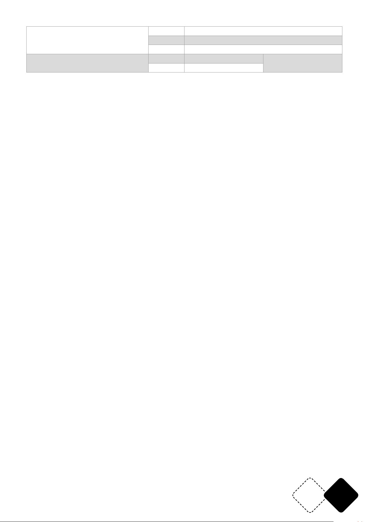
CH53
230-239 Static color 23 (10<=CH50 Value<=13)
240-249 Static color 24 (10<=CH50 Value<=13)
250-255 Static color 25 (10<=CH50 Value <=13)
0-9 No Function
10-255 Slow->Fast
Strobe (Strobe)
www.afx-light.com
EN31
Page 32
© Copyright LOTRONIC 2019
 Loading...