

AFX WTA232AMV User Manual [en, es]
WTA WTK Series
Models 217/220/232/240/417/420/432/440
Safety Precautions
Read all safety precautions and installation instructions carefully
before installing or servicing this fixture. Failure to comply with
these instructions could result in potentially fatal electric shock
and/or property damage.
It is recommended that all wiring be performed by a qualified
electrician. This fixture must be wired in accordance with all national
and local electrical codes.
Do not handle any energized fixture or attempt to energize any
fixture with wet hands or while standing on a wet or damp surface or
in water.
Make sure that the power source conforms to the requirements of the
Surface Mounted Fluorescent Fixture
fixture (see labels on fixture housing). Model numbers ending in MV
are designed for use in a 120-277VAC, 60Hz fused circuit (do not
use on a dimming circuit); otherwise the fixture is designed for use in
a 110-120VAC, 60Hz fused circuit.
To reduce the risk of electrical shock, and to assure proper operation,
this fixture must be adequately grounded. To accomplish proper
grounding, there must be a separate ground wire (green) or bare metal
contact (metal conduit) between this fixture and the ground
connection of your main power supply panel. The green ground
screw location is clearly marked on the fixture housing.
This fixture is intended to be used for dry locations only.
Assembly Instructions
1.
Preparing for installation.
A. Disconnect electrical power before installing or servicing any part of this fixture.
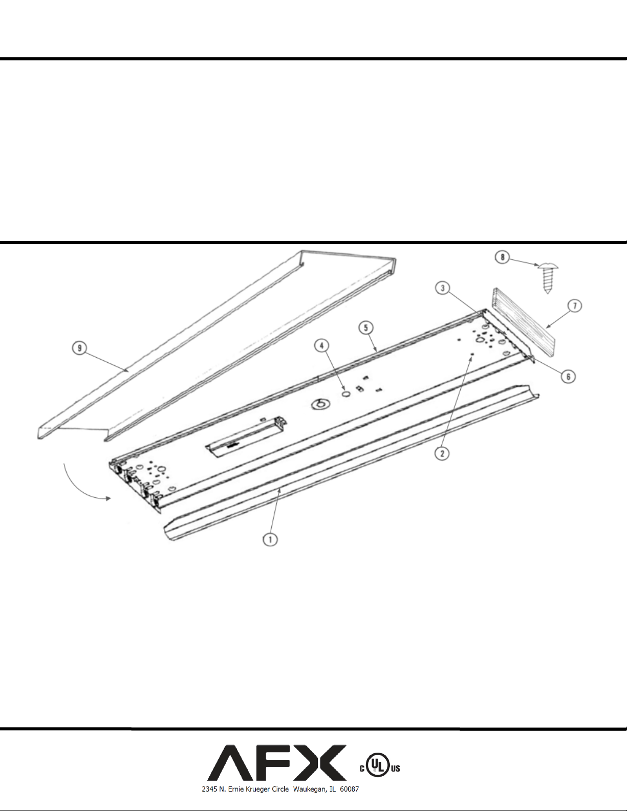
B. After removing fixture from carton, place unit on a flat surface. To gain access to wiring compartment, remove ballast cover
(1) by pressing at the dimples (2) on the channel (5) and rotating up and off.
C. Remove appropriate knockout(s) (4) for power supply entry.
D. WTK models - Punch out small knockouts (6) in each end panel of fixture housing (3). Mount the wood end panels (7) to
each metal end with screws (8) provided.
2.
Fixture mounting.
Page 1 of 4 8060188 rev.5

WTA WTK Series
Models 217/220/232/240/417/420/432/440
A. To locate, hold channel (5) up to ceiling with power supply knockout (4) located over entryway for power supply wires.
Mark the locations of the mounting holes on the ceiling. Take the channel down and punch a small hole into the ceiling at
each location using a nail or an awl to see if there is a wood joist. If there is a joist use a suitable wood screw (not included)
to mount the channel. Where there is no joist to screw into use a ¼” toggle bolt (not included) of suitable length to mount
channel (5) securely to the ceiling. Proceed to step 2.B. before final mounting.
B. Feed the black and white supply wires, and the green ground wire into the fixture through open knockout hole. At this time
you can finish mounting the fixture to the ceiling.
3.
Wiring.
Caution: Make sure power is off at fuse or circuit breaker box. Check power wires for damage or scrapes. If power supply wires
are within three inches of ballast use wire suitable for at least 90C (194F). Note: Most dwellings built before 1985 have supply
wire rated to 60C. Consult a qualified electrician before installing.
A. This unit will not operate properly unless connected to a “grounded” electrical circuit. Electrical shock, over heating, low or
B. Using wire connectors (not provided), connect white supply wire to white ballast lead. Connect black hot supply wire to
C. Replace ballast cover (1) by placing one edge of ballast cover into dimples (2), swing upward, press cover allowing second
no light output, and shortened lamp life can result if proper grounding is not done. Securely attach green (or green and
yellow) wire to provided green ground screw.
black ballast lead. Do not mix wires. Pull on each wire lead to make sure connections are secure. Make certain no bare wires
are exposed outside of wire connectors. All splice connections are to be inside the junction box.
edge to catch second set of dimples and lock in place. Make sure no wires become crimped between cover (1) and channel
(5).
Surface Mounted Fluorescent Fixture
4. Lamps - Install appropriate lamps (not included) by inserting lamp pins into lamp holder. Rotate into place to seat lamp for proper
connection. Verify all lamp holders remain properly installed into the channel (5).
5. Install diffuser (9) by hooking one edge onto channel (5) and swinging the other up and over the channel lip. Shift diffuser over
until it fits flush and appears straight.
6. Restore power at fuse or circuit breaker box.
Limited Factory Warranty
AFX hereby warranty that this fixture is free from defects in materials and workmanship when installed and used under normal operating conditions
for a period of 2 years from date of purchase. This warranty covers all component parts and extends only to replacement of defective fixture or
components; it does not cover failure due to improper installation, misuse, mishandling or damage incurred in transit.
Page 2 of 4 8060188 rev.5
 Loading...