

Page 1
VTL Series Vapor Tight Strip Light
Models: 228-8MV, 228MV, 232-8MV, 232E8EM 120-277VAC 50/60Hz
232MVEM, 232MVHL, 232MVEM, 232MVHL
232E8, 232MV, 254HO-8MV, 254HOMV
Safety Precautions
Read all safety precautions and installation instructions carefully
before installing or servicing this fixture. Failure to comply with these
instructions could result in potentially fatal electric shock and/or
property damage.
It is recommended that a qualified electrician perform all wiring. This
fixture must be wired in accordance with all national and local
electrical codes.
Do not handle any energized fixture or attempt to energize any fixture
with wet hands or while standing on a wet or damp surface or in water.
Installation Instructions
1. Warning: Disconnect electrical power before
installing this fixture.
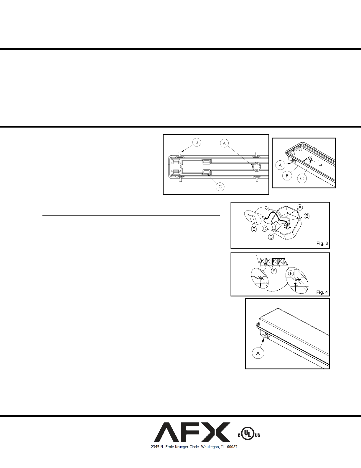
2. Release latches (Fig. 2-A) and remove diffuser.
Release gear assembly from housing clips (Fig. 2-B).
Gear tray is tethered to housing (Fig. 2-C).
3. Identify indentations in fiberglass housing for desired
power entry. Holes are supplied for end connections
and are capped with hole plugs. Top power entry
openings will need to be drilled. (Fig. 1-A)
4. Indentations are provided for mounting. Drill holes through housing at appropriate
locations. (Fig. 1-C) Warning – drilling holes in the housing is only permitted
for damp locations. For wet locations, use the mounting bracket kit (included).
5. Install latches into fiberglass housing latch mounting slots. (Fig. 1-B & 2-A)
6. To locate, hold fixture assembly up to ceiling with power supply knockout located
over entryway for power supply wires. Mark the locations of the mounting holes on
the ceiling.
7. Take the fixture down and punch a small hole into the ceiling at each location using
a nail or an awl to see if there is a wood joist. Attach to surface using fasteners and
sealing washers (by others) appropriate to ceiling materials.
8. If there is a joist, use a suitable wood screw (not included) to mount the channel.
(Fig. 4-A) Where there is no joist to screw into, use a toggle bolt (not provided)
(Fig. 4-B) of suitable length to mount housing securely to the ceiling.
9. Mount the fixture with appropriate mounting hardware (Fig. 4-A or B) while passing
the supply power wire (Fig. 3-B), the supply neutral wire (Fig. 3-A) and the supply
ground wire (Fig. 3-C) from junction box (Fig 3-D) or power supply through the
appropriate knockout hole into the fixture.
10. Use wire nut to connect white wire from ballast to neutral supply wire. (Fig. 3-A) Strip
supply wires if needed. (Fig. 3-E) Use wire nut to connect black wire from ballast to power
supply wire. (Fig. 3-B) Cover wire nuts and connections completely in electrical tape. Secure
bare or green ground wire to green screw in the channel. Note – for models with luminaire
disconnect pre-wired to ballast, reference the included instruction insert.
11. Re-install gear assembly to housing by snapping into clips (Fig. 2-B)
12. Install appropriate lamp(s) (not included) by inserting lamp pins into lamp holder. Rotate
into place to seat lamp for proper connection.
13. Mount Fiberglass diffuser onto Fiberglass housing, Secure by rotating latches around edge of
housing and capturing diffuser with rounded lip, snap latch closed. 6 or 12 latches total.
(Fig. 5-A). Restore power.
This fixture is designed for use in a 120-277VAC, 50/60Hz fused
circuit. Do not use on a dimming circuit.
To reduce the risk of electrical shock, and to assure proper operation,
this fixture must be adequately grounded. To accomplish proper
grounding, there must be a separate ground wire (green) contact
between this fixture and the ground connection of your main power
supply panel.
This fixture is intended to be mounted 4ft above ground and used for
general indoor or outdoor lighting in wet locations.
Fig. 1
Fig. 2
Fig. 5
Limited Factory Warranty
AFX warrants this fixture is free from defects in materials and workmanship when installed and used under normal operating conditions for a period
of 2 years from date of purchase. This warranty covers all component parts and extends only to replacement of defective fixture or components; it
does not cover failure due to improper installation, misuse, mishandling or damage incurred in transit.
1 of 1
8060301 R8
 Loading...