

AFX TYS1123213QMVSN User Manual
TYS Series Fluorescent Wall Sconce
Models 213, 218, & 226
Safety Precautions
Read all safety precautions and installation instructions
carefully before installing or servicing this fixture. Failure to
comply with these instructions could result in potentially fatal
electric shock and/or property damage.
It is recommended that a qualified electrician perform all
wiring. This fixture must be wired in accordance with all
national and local electrical codes.
Do not handle any energized fixture or attempt to energize any
fixture with wet hands or while standing on a wet or damp
surface or in water.
For model with MV at the suffix, this fixture is designed for
use in a 120-277VAC, 60Hz. For models with SCT at the
Assembly Instructions
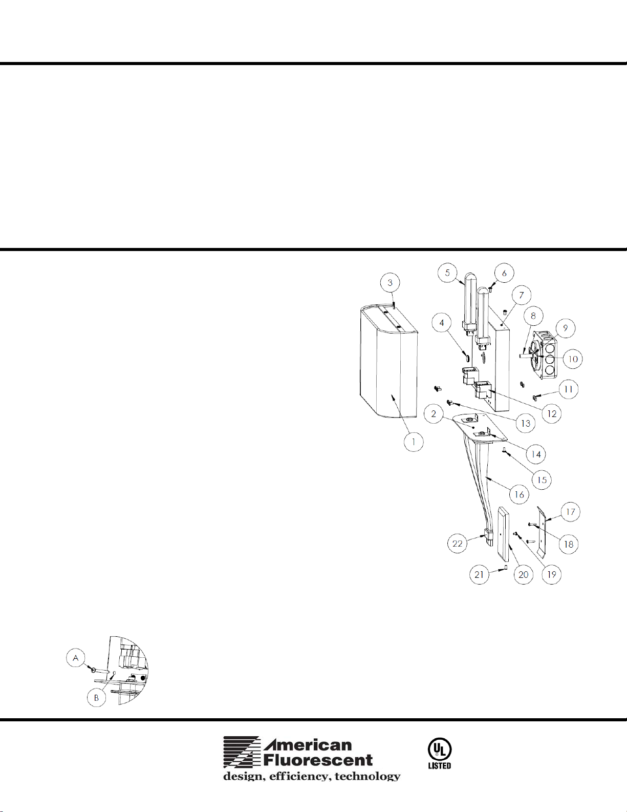
1. Preparing for installation-
A. Disconnect electrical power before installing or servicing any
part of this fixture.
B. Remove shade assembly (1), cast arm assembly (16) and backpan
assembly (7) from cartons. Separate contents of hardware bag.
2. Arm Assembly-
A. Make sure the cover plate (20) is securely assembled with the
finial (22) and be able to mount it with the bracket plate (17).
B. Attach and align the two brackets (14) on the arm assembly with
the backpan (7) bottom holes and secure with the screws (13) and
hex nuts (11) provided.
C. Secure the bottom diffuser (2) by aligning the holes with the
threaded holes on the backpan (7) and secure with the screws (15)
provided.
3. Wiring- all wiring must take place inside junction box.
Caution: Make sure power is off at fuse or circuit breaker box. Check
power wires for damage or scrapes. If power supply wires are within three
inches of ballast use wire suitable for at least 90C (194F). Note: Most
dwellings built before 1985 have supply wire rated to 60C. Consult a
qualified electrician before installing.
A. Attach gem bar (10) to junction box (not provided) with two of
the long screws provided. Install the long threaded stem (8) by
screwing to the gem bar (10).
B. Securely attach green (or green and yellow) wire to bare wire
from junction box.
C. Using luminaire disconnect (provided), insert white supply wire
into the hole across from white ballast lead. Insert black hot
supply wire into hole across from black ballast lead. Do not mix wires. Pull on each wire to make sure connections are
secure. Make certain no bare wires are exposed outside of luminaire disconnect.
D. Tuck all connections neatly into junction box.
suffix, this fixture is designed for use in a 120VAC, 60Hz. Do
not use the MV fixture on a dimming circuit. The SCT fixture
is dimmable (Consult with American Fluorescent for GU24
dimmable lamps to use)
To reduce the risk of electrical shock, and to assure proper
operation, this fixture must be adequately grounded. To
accomplish proper grounding, there must be a separate ground
wire (green) or bare metal contact (metal conduit) between
this fixture and the ground connection of your main power
supply panel. The green ground screw location is clearly
marked on the fixture housing.
This fixture is intended for use for general indoor lighting in
dry or damp locations only.
Page 1 of 2 8060610 rev.0
TYS Series Fluorescent Wall Sconce
Models 213, 218, & 226
4. Mounting-
A. Adjust threaded stem (8) in gem bar (10) so that approx. 1-3/8” is exposed and tighten with locknut (9). Either use fixture as
a template for mounting bracket plate (17) positioning OR measure 18” from center of threaded stem (8) to the bottom of the
mounting bracket plate (17) and mark for bracket plate mounting hole. Drill 1/8” pilot hole.
B. Attach mounting bracket plate (17) to wall with anchor(s) (if required) and ¾” screw(s) (18) provided.
C. Place the cover plate (20) at the bottom of fixture arm(s) (16) onto mounting bracket plate (17) and
swing up and over stem (8). Secure with thumbscrew (4) and secure the cover plate with the screw
(21) provided.
D. Install wood screw (A) into anti-rotational hole (B) in back pan to prevent the fixture from rotating.
(See Fig 2)
Lamp -Install appropriate lamp(s) (not provided) per label on face of backpan. Insert lamp pins (5) into
lamp holder (12) and press downwards until lamp (5) snaps in place. Lamp Installation (Lamps included
on models ending with “SCTD”).
A. For model with MV at the suffix, use only as required per label on the face of the backpan (7)
fluorescent, quad 4-pin lamps (5). To install, line-up lamp pins with the corresponding holes in th e
lamp holder (12) and push lamp into place until a click is heard. Repeat for each lamp.
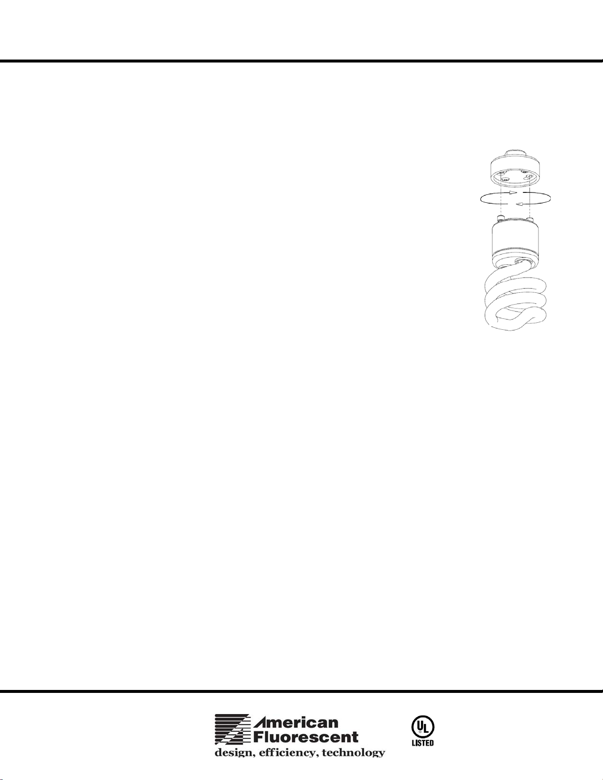
B. For models with SCT at the suffix, (See Fig 3) usable on a dimming circuit with dimmable GU24
base lamps, use only GU24 base lamps (26W max.). To install, line up lamp pins with the
corresponding holes in lamp socket and turn clockwise until a click is heard. Repeat for each lamp.
NOTE: BE CAREFUL TO HOLD THE SOCKET DURING ROTATING LAMP
INSTALLATION/REPLACEMENT
5. Shade -To install the shade assembly (1), align the two holes on the diffuser with the two holes on the top of the backpan (7) and
secure with short screws (6).
6. Restore power at fuse or circuit breaker box.
Limited Factory Warranty
American Fluorescent Corporation hereby warranty that this fixture is free from defects in materials and workmanship when installed and used under normal operating
conditions for a period of 2 years from date of purchase. This warranty covers all component parts and extends only to replacement of defective fixture or components;
it does not cover failure due to improper installation, misuse, mishandling or damage incurred in transit.
Page 2 of 2 8060610 rev.0
 Loading...