

Page 1
TYS Series LED Wall Sconce Fixture
Fig 2
Models TYS1123
Safety Precautions
Read all safety precautions and installation in s tructions carefully
before installing or servicing this fixture. Failure to comply with
these instructions could result in potentially fatal electric shock
and/or property damage.
It is recommended that a qualified electrician perform all wiri ng. This
fixture must be wired in accordance with all natio nal and local
electrical codes.
Do not handle any energized fixture or attempt to energize any
fixture with wet hands or while standing on a wet or damp surface or
in water.
Assembly Inst ru ct i o ns
1. Preparing for installation-
A. Disconnect electrical power before installing or servicing any part of this
fixture.
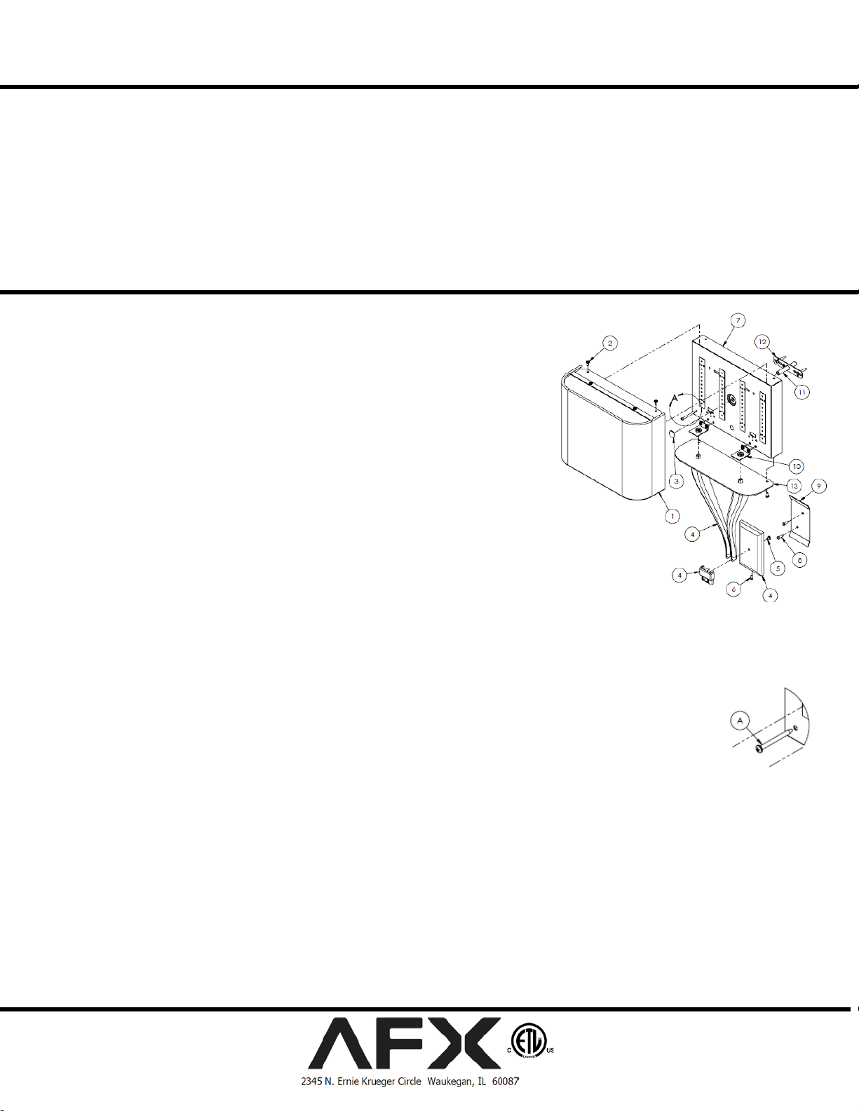
B. Remove shade assembly (1), cast arm assembly (4) and back pan assembly (7)
from cartons. Separate contents of hardware bag.
2. Arm Assembly-
A. Assemble lower cast arm assembly (4) using provided screw (5)
B. Install lower diffuser (13) over cast arm assembly (4) before assembling upper
cast arm assembly (10) using provided hardware.
C. Atta ch and align the cast arm assembly (4) with the back pan (7) and secure
with the provided nipples and hex n uts.
3. Wiring- all wiring must take pla c e inside j unction box.
Caution: Make sure power is off at fuse or circuit breaker box. Check power wires for
damage or scrapes. If power supply wires are within three inches of driver use wire
suitable for at least 90C (194F). Note: Most dwellings built before 1985 have supply
wire rated to 60C. Consult a qualified electrician before installing.
A. This unit will not operate properly unless connected to a “grounded” electrical
circuit. Electrical shock, overheating, low or no light o utput, and shortened
lamp life can result if proper grounding is not done. Securely attach green (or green and yellow) wire to back of fixture with
provided hardware.
B. Using wire nuts (provided), connect white (common) supply wire to white fixture lead. Connect black (hot) supply wire to
black fixture lead. Do not mix wires. Pull on each wire lead to make sure connections are secure. Make certain no bare wires
are exposed outside of wire connectors. Note: fixtures with universal voltage po wer supplies are pre-wired
with a disconnect. Refer to the included guide for using the disconnect
4. Mounting-
A. Adjust threaded stem (11) in gem bar (12) so that approx. 1-3/8” is exposed and tighten with locknut. Either
use fixture a s a template for mounti ng bracket plate (9) positioning OR measure 1 8” from center of threaded
stem (11) to the bottom of the mounting bracket plate (9) and mark for bracket plate mounting hole. Drill
1/8” pilot hole.
B. Attach mou nti n g bracket plate (9) to wall with anchor(s) (if required) and ¾” screw(s) (8) provided.
C. Place the lower arm assembly plate (4) onto mounting bracket plate (9) a nd swing up and over stem (11). Secure with
thumbnut (3) and secure the lower cover plate with the screw (6) provided.
D. Install wood screw (A) into anti-rotational hole on back pan t o prevent the fixture from rotating. (See Fig 2)
5. Shade-
A. To install the shade assembly (1), align the two holes on the diffuser with the two holes on the top o f t he back pan (7) and
secure with short screws (2).
B. Restore power at fuse or circuit breaker box.
Limited Factory Warranty
AFX Inc. hereby warranty that this fixture is free from defects in materials and workmanship when installed and used under normal operating conditions for a period of
5 years from date of shipment from factory. This warranty covers all component parts and extends only to replacement of defective fixture or components; it does not
cover failure due to improper installation, misuse, mishandling or damage incurred in transit.
Page 1 of 1 8060762 R0
Make sure that the power source conforms to the requirements of the
fixture (see labels on fixture housing).
To reduce the risk of electrical shock, and to assure proper operation,
this fixture must be adequately grounded. To accomplish proper
grounding, there must b e a s eparate ground wire (green) o r bare metal
contact (metal conduit) between this fixture and the ground
connection of your main power supply panel. The green ground
screw location is clear ly marked on the fixture housing.
This fixture is intended for use for general indoor lighting in dry or
damp locations only.
 Loading...