

Page 1
Outdoor Fixtures
Fluorescent Ceiling Fixture
Models: 324502, 324504, TPFW113WHPLT & TPFW213WHPLT 120VAC / 60Hz
Read all safety precautions and installation instructions carefully before
installing or servicing this fixture. Failure to comply with these
instructions could result in potentially fatal electric shock and/or
property damage.
It is recommended that a qualified electrician perform all wiring. This
fixture must be wired in accordance with all national and local
electrical codes.
Do not handle any energized fixture or attempt to energize any fixture
with wet hands or while standing on a wet or damp surface or in water.
This fixture is designed for use in a 110-120VAC, 60Hz fused circuit.
Do not use on a dimming circuit.
To reduce the risk of electrical shock, and to assure proper operation,
this fixture must be adequately grounded. To accomplish proper
grounding, there must be a separate ground wire (green) contact
between this fixture and the ground connection of your main power
supply panel.
This fixture is intended to be used for general outdoor lighting in dry or
damp locations only.
ASSEMBLY INSTRUCTIONS
1. Preparing for installation
A. Disconnect electrical power at fuse or circuit breaker box before installing or servicing any part of this fixture.
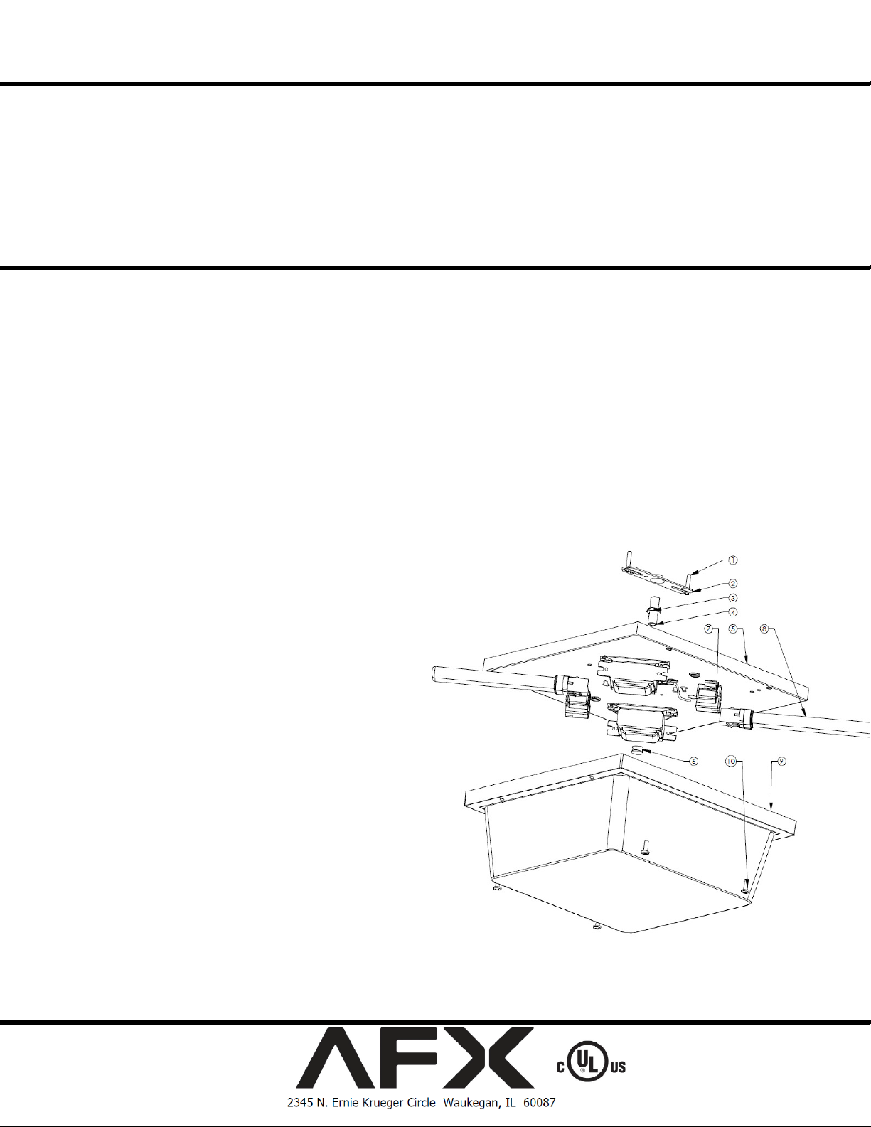
B. Carefully remove the fixture from the carton, and check that all parts are included, as shown in figure below. Be careful not to
misplace any of the screws or parts which are needed for installing the fixture.
2. Wiring-all wiring must take place inside junction box.
Caution: Make sure power is off at fuse or circuit breaker box. Check power wires for damage or scrapes. If power supply
wires are within three inches of the ballast power supply, use wire suitable for at least 90C (194F). Note: Most dwellings built
before 1985 have supply wire rated to 60C. Consult a qualified electrician before installing.
A. Attach gem bar (2) to junction box (not supplied) with two screws (1) (supplied).
B. Attach threaded stem (4) to gem bar and secure it with the hex nut (3) leaving about ¾” stem length exposed.
C. Make all wire connections to appropriate wire. Secure with wire nuts (supplied).
D. Connect the green wire from the fixture to the power source the green ground wire.
E. The black wire from the fixture is connected to the
black wire from power source.
D. The white wire from the fixture is connected to the
white (neutral) wire from power source.
E. Tuck all connections neatly into junction box.
3. Mounting
A. Align the backpan (5) center hole over threaded
stem (4). Secure the backpan with the thumbscrew
(6).
Lamp- Install appropriate lamp(s) (not supplied) per
label. Insert lamp (8) into lamp holder (7) and press
upwards until lamp snaps in place.
4. Shade-Secure the shade (10) with four screws (9).
5. Restore power at fuse or circuit breaker box.
Limited Factory Warranty
AFX warrants this fixture is free from defects in materials and workmanship when installed and used under normal operating conditions for a period of 2 years from
date of purchase. This warranty covers all component parts and extends only to replacement of defective fixture or components; it does not cover failure due to
improper installation, misuse, mishandling or damage incurred in transit
1 of 1
8060654 R3
 Loading...