

Page 1

TAP SERIES Taylor
Model 225 Ceiling Mounted Fixture
Safety Precautions
Read all safety precautions and installation instructions carefully
before installing or servicing this fixture. Failure to comply with
these instructions could result in potentially fatal electric shock
and/or property damage.
It is recommended that a qualified electrician perform all wiring. This
fixture must be wired in accordance with all national and local
electrical codes.
Do not handle any energized fixture or attempt to energize any
fixture with wet hands or while standing on a wet or damp surface or
in water.
Tools Required: Phillips Screwdriver, Adjustable Wrench & Pliers. Hardware Required: Appropriate mounting hardware
Assembly Instructions
1. Preparing for installation
A. Consult a local licensed electrician or electrical contractor about
installing the fixture if you are not sure about installation.
B. Select a suitable location (for indoor use only).
2. Installing Fixture Mounting Plate (Fig 1) (Fixture Total
Load Weight: 19 lbs)
A. Before you install the mounting plate (3) that is shown in Fig 1,
make sure the two #8 screws, two lock washers and two hex
nuts are installed to the plate (5). Fish the wires from canopy
assembly and wires from junction box thro u gh center hole on
mounting plate (3). Align center of mounting plate (3) to
junction box.
B. To rigidly secure the plate; we recommend mounting to a
junction box and using the included support hardware,
consisting of; wood screws (4) and anchors ( included) at the
four ¼” diameter hole locations at both ends of the plate (3).
3. Install Canopy / Stem to Plate Assembly (Fig 1)
A. Align the 2 holes on the canopy (7) to the plate (3). Align the
two #8-32x1inch studs to the holes in the canopy and use the
ball nuts (8) to secure the canopy.
B. Feed the supply wires through the stem (9). Place a bead of
loctite (included) to threads of nipple attached to swivel
assembly and fasten the end of the stem to the nipple that is
attached on the swivel bracket assembly (6). Repeat these
procedures to connect the other stem (without wires) to the
swivel bracket assembly (6). Note: When tightening the stem
to the threads of the nipple from swivel bracket assembly,
make sure that the swivel ball groove is locked in place to
the bracket tab.
4. Channel Assembly (FIG 2 and DETAIL A)
A. Remove #8 screw (20) from channel assembly separating the cover (2) from channel
(1) and set aside.
B. Make sure when mounting channel assembly that the ballast is on the same side as the
stem that has the wires.
1 of 2 8060509 r0
This fixture is designed for use in a 120-277V, 50/60Hz circuit. Do
not use on a dimming circuit.
To reduce the risk of electrical shock, and to assure proper operation,
this fixture must be adequately grounded. To accomplish proper
grounding, there must be a separate ground wire (green) or bare metal
contact (metal conduit) between this fixture and the ground
connection of your main power supply panel. The green ground
screw location is clearly marked on the fixture housing.
This fixture is intended to be used for dry or damp indoor, lighting
locations.
FIG. 2
DETAIL A
Page 2
TAP SERIES Taylor
prop
Model 225 Ceiling Mounted Fixture
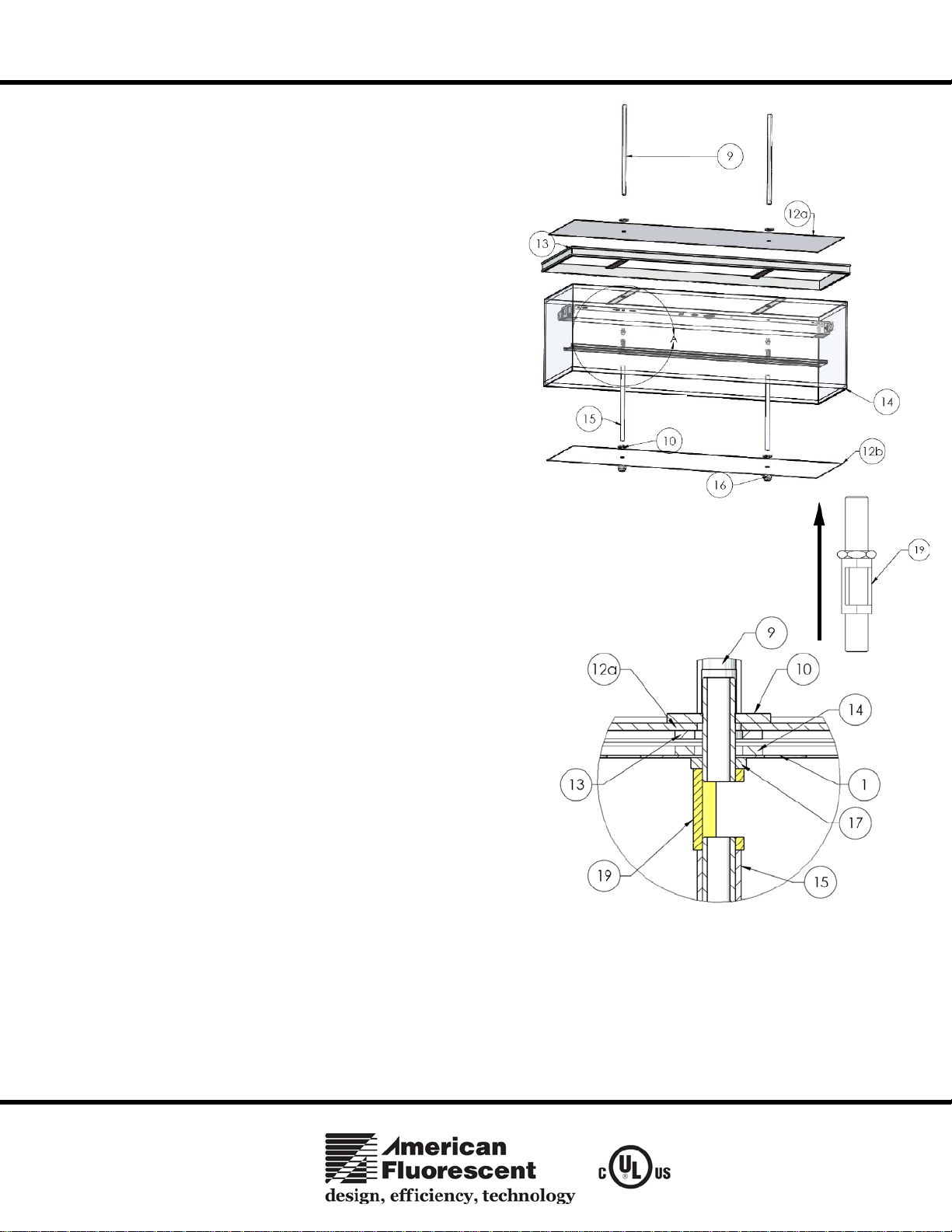
5. Frame and Diffuser Assembly (FIG 3 and DETAIL B)
A. Align holes from channel, diffuser mounti n g brac ket , frame
bracket and upper diffuser (12a) with hickey assembly (19)
with hexnut facing up and thread.
B. Assemble the Linen Diffuser (14) with the polished chrome
frame (13) on top aligning the mounting brackets. Next, place
the acrylic diffuser (12a) with the matte side facing up.
C. Thread washer (10) onto hickey assembly (19) and loosely
tighten.
D. Feed black and white power wires into hickey assembly on
either side and pull wires through center opening of hickey
assembly (19).
E. Thread hickey assembly into one stem (9) at a time until both
stems are secure.
F. Tighten hickey assembly (19) from the inside of the channel.
6. Wiring the Fixture
A. Connect the ballast black wire with the black wire from stem,
connect the white ballast wire to the white wire of the stem
using the provided wire nuts.
B. Re-install the channel cover (2) as it is shown in Detail A.
Install white stems (15) into bottom of hickey assembly (19) at
the threaded nipples inside the channel. Place threaded nipple
at bottom of stem (15) and thread washer (10) onto nipple.
Install the lower diffuser (12b) with matte side facing down
and secure with finial (16).
C. To connect the power service in-line wires. Remove the
thumbnuts (8) and canopy (7). With the wire nuts provided,
connect the power service in-line black wire to the black wire
from the swivel bracket assembly (A), with the use of the wire
connectors provided. Connect the power service in-line white
wire to the white wire of the stem bracket assembly (A). Connect
the ground wire and the power service in-line ground w ire to the
plate.
D. Replace the canopy (7) and fasten the two thumb nuts (8).
E. RESTORE POWER
FIG. 3
B
DETAIL B
Limited Factory Warranty
American Fluorescent Corporati on hereby warranty that this fixture is free from defects in materials and w orkmanship when installed and used under normal operating conditions for a
period of 2 years from date of purchase. This warranty covers all component parts and extends only to replacement of defective fixture or components; it does not cover failure due to
im
er installation, misuse, mishandling or damage incurred in transit.
2 of 2 8060509 r0
 Loading...