

Page 1
TAF Series Linkable Fluorescent Ceiling Fixture
Model 155
Safety Precautions
Read all safety precautions and installation instructions carefully before
installing or servicing this fixture. Failure to comply with these instructions
could result in potentially fatal electric shock and/or property damage.
It is recommended that a qualified electrician perform all wiring. This fixture
must be wired in accordance with all national and local electrical codes.
Do not handle any energized fixture or attempt to energize any fixture with
wet hands or while standing on a wet or damp surface or in water.
Assembly Instructions
1. Preparing for installation
A. Disconnect electrical power before installing or servicing any part of
this fixture.
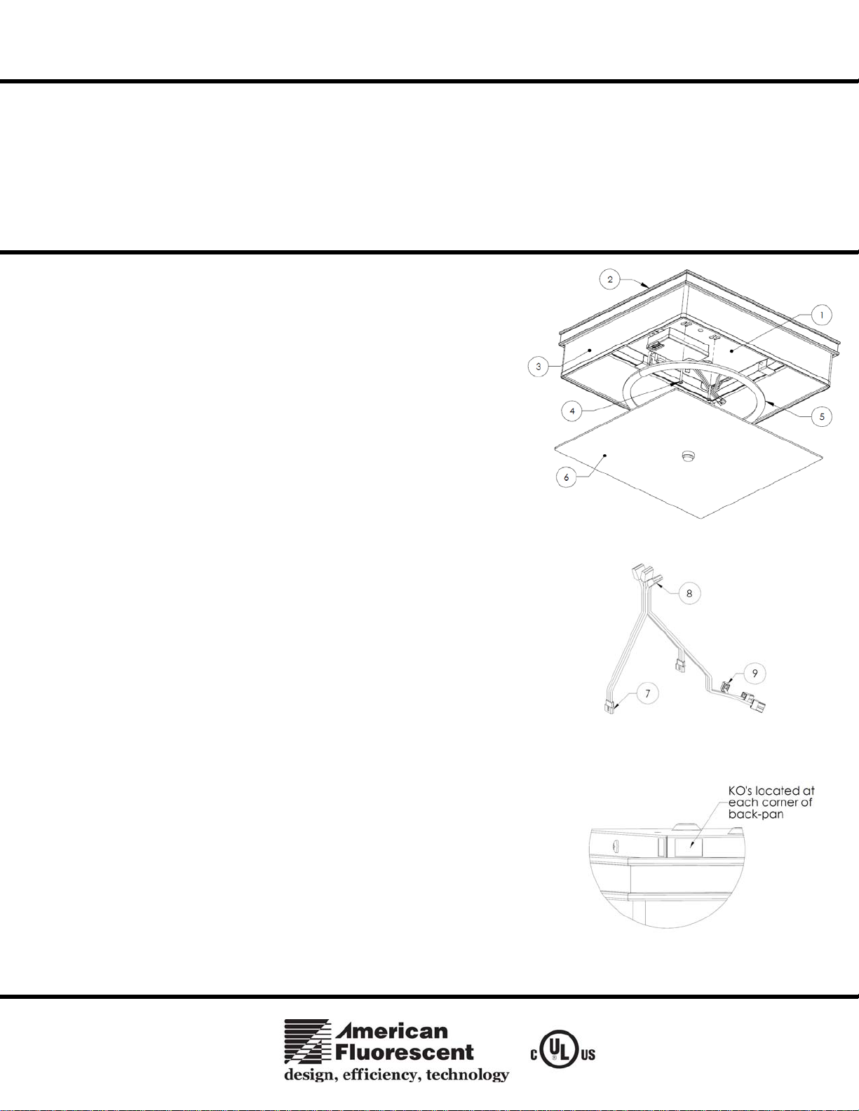
B. Remove fixture from carton, set ceiling-pan assembly aside (shade (3),
decorative frame (2) and ceiling-pan (1) are pre-assembled). Open
hardware bag and remove contents.
2. Wiring
All wiring must take place inside junction box.
Caution:
for damage or scrapes. If power supply wires are within three inches of ballast; use
wire suitable for at least 90C (194F). Note: Most dwellings built before 1985 have
supply wire rated to 60C. Consult a qualified electrician before installing. This unit
will not operate properly unless connected to a “grounded” electrical circuit.
Electrical shock, overheating, low or no light output, and shortened lamp life can
result if proper grounding is not done.
A. Using wire connectors on harness (see figure 2); connect white supply
Make sure power is off at fuse or circuit breaker box. Check power wires
wire to white wire 2-pin connector (9) (Note: slide wire protective sleeving
away from connector to see wire color); insert the stripped wire end into
the open pin-hole location of the connector (9). Connect black hot
supply wire to black wire 2-pin connector (9); insert the stripped wire
end into the open pin-hole location of the connector. Follow the same
instructions to connect the ground wire. Do not mix wires . Pull on each
wire lead to make sure the connections are secure. Make certain no bare
wires are exposed outside of wire connectors.
(see figure 1)
This fixture is designed for use in a 120-277VAC, 60Hz. Do not use on a
dimming circuit. Maximum of 10 linkable units on a circuit.
To reduce the risk of electrical shock, and to assure proper operation, this
fixture must be adequately grounded. To accomplish proper grounding, there
must be a separate ground wire (green) or bare metal contact (metal conduit)
between this fixture and the ground connection of your main power supply
panel. The green ground screw location is clearly marked on the fixture
housing.
This fixture is intended for use for general indoor lighting in dry or damp
locations only.
FIGURE 1
3. Ballast Wiring
A. Using wire connectors (8) on harness, insert white wire from ballast to
white wire 4-pin connector (8); insert the stripped wire end into the
FIGURE 2
open pin-hole location of the connector (8). Connect black wire from
ballast to black wire 4-pin connector (8); insert the stripped wire end
into the open pin-hole location of the connector (8). Follow the same
instructions to connect the ground wire. Do not mix wires . Pull on each
wire lead to make sure the connections are secure. Make certain no bare
wires are exposed outside of wire connectors.
4. Mounting (Hardwired Unit)
A. Attach ceiling-pan (1) to junction box (not provided) through keyhole
slots with #8-32 x 1-1/8” screws (4 - provided) .
Page 1 of 2 8060535 Rev.2
FIGURE 3
Page 2
TAF Series Linkable Fluorescent Ceiling Fixture
Model 155
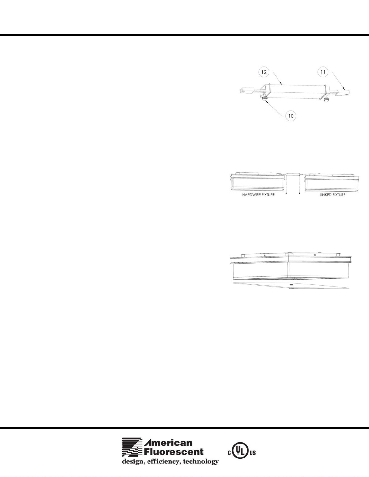
5. Preparing for Additional Fixture Linking
NOTE: Wire way channel creates a fixed 3 ¾” spacing between ceiling pans.
A. Locate and remove appropriate knock-out on the back-pan (1).
B. Hold up second fixture and mark appropriate knock- out in line with first
hardwired fixture.
C. Remove the knock-out on linked unit and insert one end of wire way
channel (12) into the knock-out from the first hardwired unit. Secure the
wire-way channel with the thumb screw (10 - provided) inside the
diffuser.
Linking Additional Fixtures
6.
A. (See figure 5) Align wire-way channel into second fixture knock-out and
mark keyhole mounting locations. Verify flange from wire-way channel
is flush on both fixtures.
FIGURE 4
B. Take the linking fixture down and locate the ceiling joists with a stud
finder or punch a small hole into the ceiling at each location; using a nail,
verify there is a wood joist. If there is a joist, use a suitable wood screw
(not included) to mount the channel. Where there is no joist to screw
into, use a ¼” toggle bolt (not included) of suita bl e length to mount
channel securely to the ceiling.
C. Secure the wire-way channel with the thumb screw (10 - provided)
inside the diffuser.
D. Attach linked fixture connector (7) to connector (11) on the inside of
each fixture to link fixtures. Maximum number of linkable fixtures:
10 units.
7. Fixture Lamping
A. This fixture uses one FC12T5 55W high output circline lamp (5 -
provided).
B. Align lamp (5) pins into socket. Press lamp into lamp clips until lamp
is secured at all locations. Press lamp pins into socket until pins snap
in place and are secured.
8. Bottom Diffuser Installation
A. (See figure 6) Assemble lower diffuser by inserting one corner into the
inside of the base diffuser allowing it to rest on the inside edge.
Lift up the rest of the diffuser edges and allow the lower diffuser to
rest on inside of the main diffuser edge.
9. Restore power at fuse or circuit breaker box
FIGURE 5
FIGURE 6
Limited Factory Warranty
American Fluorescent Corporation hereby warranty that this fixture is free from defects in materials and workmanship when installed and used
under normal operating conditions for a period of 2 years from date of purchase. This warranty covers all component parts and extends only to
replacement of defective fixture or components; it does not cover failure due to improper installation, misuse, mishandling or damage incurred in
transit.
Page 2 of 2 8060535 Rev.2
 Loading...