

Page 1
NLV Series Fluorescent Vanity Fixture
Models 214, 221, 228
Safety Precautions
Read all safety precautions and installation instructions carefully
before installing or servicing this fixture. Failure to comply with
these instructions could result in potentially fatal electric shock
and/or property damage.
It is recommended that a qualified electrician perform all wiring. This
fixture must be wired in accordance with all national and local
electrical codes.
Do not handle any energized fixture or attempt to energize any
fixture with wet hands or while standing on a wet or damp surface or
in water.
Assembly Instructions
1. Preparing for installation
A. Disconnect electrical power before installing or servicing
any part of this fixture.
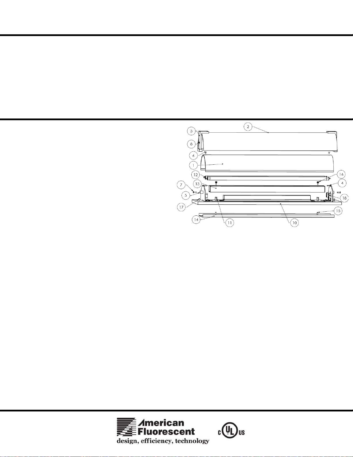
B. After carefully unpacking the fixture, remove the ballast
cover (13) by removing the 2 thumbscrews (16) and pulling
cover (13) off back-pan (10). Also remove the mounting plate
(14) from the back-pan (10).
C. Use a level to verify mounting plate (14) is level and install
mounting plate (14) to junction box with #8 screws (not
provided). For added security, add wood screws and anchors
(included) to mount fixture mounting plate at keyhole
locations to wall.
D. Pull supply wires through wire hole in mounting plate and
fixture leads from ballast through hole in back-pan (10).
2. Wiring.
All wiring must take place inside junction box.
Caution: Make sure power is off at fuse or circuit breaker box. Check power wires for damage or scrapes. If power supply wires are within three
inches of ballast, use wire suitable for at least 90C (194F). Note: Most dwellings built before 1985 have supply wire rated to 60C. Consult a qualified
electrician before installing.
A. This unit will not operate properly unless connected to a “grounded” electrical circuit. Electrical shock, over heating, low or no light
output, and shortened lamp life can result if proper grounding is not done.
B. Using luminaire disconnect (provided), insert white supply wire into the hole across from white ballast lead. Insert black hot supply wire
into hole across from black ballast lead. Do not mix wires. Pull on each wire to make sure connections are secure. Make certain no bare
wires are exposed outside of luminaire disconnect.
C. Line up studs (15) from mounting plate (14) with hole in back-pan (10) and secure with standoffs (11). Use a level to verify mounting pan
(14) and back-pan (10) are level.
D. Replace the ballast cover (13) by lining up the holes with the threaded studs (16) and the standoffs (11) and thread securely.
3. Fixture Lamping.
A.
This fixture uses 2 – 14, 21 of 28 watt T5 linear fluorescent lamps (12 - not provided).
B. Inserting lamp (12) pins into sockets (18) and rotate until lamp snaps into place.
This fixture is designed for use in a 120-277VAC, 60Hz. Do not use
on a dimming circuit.
To reduce the risk of electrical shock, and to assure proper operation,
this fixture must be adequately grounded. To accomplish proper
grounding, there must be a separate ground wire (green) or bare metal
contact (metal conduit) between this fixture and the ground
connection of your main power supply panel. The green ground
screw location is clearly marked on the fixture housing.
This fixture is intended for use for general indoor lighting in dry or
damp locations only.
4. Diffuser installation.
A. Line the holes on inner diffuser (1) with holes on diffuser mounting bracket (4), place diffuser over brackets and attach with screws (6).
B. Mount short leg of L-bracket (not shown) to the outer glass diffuser (2) at each end so the other leg is flush with the edge of the glass. Be
sure to place rubber washer between the screw head and the outside surface of the glass.
C. Attach the arm bracket (3) to the longer leg of the L-bracket using the pair of screws attached to the bracket. Repeat on the opposite end of
the glass.
D. Align outer diffuser (2) with brackets (3) to back-pan (10) studs (17). Fasten arm bracket location (8) to arm mounting plate standoff (5)
and fasten with screws (7).
E. Restore power at fuse or circuit breaker box.
Limited Factory Warranty
American Fluorescent Corporation hereby warranty that this fixture is free from defects in materials and workmanship when installed and used under normal operating
conditions for a period of 2 years from date of purchase. This warranty covers all component parts and extends only to replacement of defective fixture or components;
it does not cover failure due to improper installation, misuse, mishandling or damage incurred in transit.
Page 1 of 1 8060520 Rev.3
 Loading...